
This document provides a reference to the basics of HAL.
1. Команди HAL
More detailed information can be found in the man page for halcmd: run man halcmd in a terminal window.
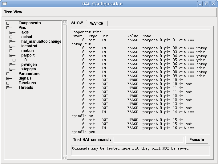
Щоб переглянути конфігурацію HAL та перевірити стан контактів і параметрів, скористайтеся вікном «HAL Configuration» (Конфігурація HAL) в меню «Machine» (Машина) в AXIS. Щоб переглянути стан контакту, відкрийте вкладку «Watch» (Перегляд) і натисніть на кожен контакт, який ви хочете переглянути, і він буде доданий до вікна перегляду.
1.1. loadrt
The command loadrt loads a real time HAL component. Real time component functions need to be added to a thread to be updated at the rate of the thread. You cannot load a non-realtime component into the realtime space.
loadrt <component> <options>
loadrt mux4 count=1
1.2. addf
The addf command adds a function to a real-time thread. If the StepConf wizard was used to create the configuration, two threads have been created (``base-thread`` and ``servo-thread``).
addf додає функцію functname до потоку threadname. За замовчуванням функції додаються в тому порядку, в якому вони знаходяться у файлі. Якщо вказано position, функція додається до цього місця в потоці. Від’ємне значення position вказує на позицію відносно кінця потоку. Наприклад, «1» — початок потоку, «-1» — кінець потоку, «-3» — третє місце від кінця.
Для деяких функцій важливо завантажувати їх у певному порядку, наприклад функції читання та запису parport. Назва функції зазвичай складається з назви компонента та цифри. У наведеному нижче прикладі завантажується компонент «or2», а команда «show function» показує назву функції or2.
$ halrun
halcmd: loadrt or2
halcmd: show function
Експортовані функції:
Owner   CodeAddr  Arg       FP   Users  Name
 00004  f8bc5000  f8f950c8  NO       0   or2.0
You have to add a function from a HAL real time component to a thread to get the function to update at the rate of the thread. Usually there are two threads as shown in this example.
|
Note
|
The |
$ halrun
halcmd: loadrt motmod base_period_nsec=55555 servo_period_nsec=1000000 num_joints=3
halcmd: show thread
Realtime Threads:
     Period  FP     Name               (     Time, Max-Time )
     995976  YES          servo-thread (        0,        0 )
      55332  YES           base-thread (        0,        0 )
-
base-thread (the high-speed thread): This thread handles items that need a fast response, like making step pulses, and reading and writing the parallel port.
-
servo-thread (the slow-speed thread): This thread handles items that can tolerate a slower response, like the motion controller, ClassicLadder, and the motion command handler.
addf <function> <thread>
addf mux4.0 servo-thread
1.3. initf
The initf command registers a function to run once in realtime context, on a dedicated init cycle of the thread before the cyclic function list runs. It is the realtime-thread analogue of addf, intended for one-shot setup that must execute in the realtime task (for example EtherCAT master activation via lcec.activate).
initf adds function functname to the init list of thread threadname. The init list runs once on the first cycle after start, then is drained. The cyclic list begins on the following period. Once the init cycle has run, further initf calls on that thread are rejected. position has the same meaning as in addf.
initf <function> <thread>
initf lcec.activate servo-thread
1.4. loadusr
The command loadusr loads a non-realtime HAL component. Non-realtime programs are their own separate processes, which optionally talk to other HAL components via pins and parameters. You cannot load realtime components into non-realtime space.
Прапори можуть бути одним або кількома з наступних:
| -W |
чекати готовності компонента. Вважається, що компонент має таку ж назву, як і перший аргумент команди. |
| -Wn <name> |
чекати на компонент, який матиме задане <name>. Це застосовується лише якщо компонент має опцію name. |
| -w |
чекати на завершення програми |
| -i |
ігнорувати значення, що повертається програмою (з опцією -w) |
| -n |
назвати компонент, коли це є допустимим варіантом для цього компонента. |
loadusrloadusr <component> <options>
loadusr halui
loadusr -Wn spindle gs2_vfd -n spindleАнглійською це означає «loadusr чекати на назву шпинделя компонент gs2_vfd назва шпинделя».
1.5. net
The command net creates a connection between a signal and one or more pins. If the signal does not exist net creates the new signal. This replaces the need to use the command newsig. The optional direction arrows <=, => and <=> make it easier to follow the logic when reading a net command line and are not used by the net command. The direction arrows must be separated by a space from the pin names.
netnet signal-name pin-name <optional arrow> <optional second pin-name>
net home-x joint.0.home-sw-in <= parport.0.pin-11-inУ наведеному вище прикладі home-x — це назва сигналу, joint.0.home-sw-in — це контакт «Direction IN», <= — це необов’язкова стрілка напрямку, а parport.0.pin-11-in — це контакт «Direction OUT». Це може здатися заплутаним, але мітки входу та виходу для контакту паралельного порту вказують на фізичний спосіб роботи контакту, а не на те, як він обробляється в HAL.
Вивід можна підключити до сигналу, якщо він підпорядковується таким правилам:
-
Вивід IN завжди можна підключити до сигналу.
-
Вивід IO можна підключити, якщо на сигналі немає виводу OUT.
-
Вивід OUT можна підключити, лише якщо на сигналі немає інших виводів OUT або IO.
Одне й те саме «ім’я сигналу» можна використовувати в кількох мережевих командах для підключення додаткових контактів, якщо дотримуватися наведених вище правил.
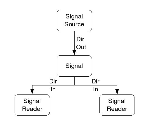
Цей приклад показує сигнал xStep, джерелом якого є stepgen.0.out, та два зчитувачі, parport.0.pin-02-out та parport.0.pin-08-out. В основному значення stepgen.0.out надсилається до сигналу xStep, а потім це значення надсилається до parport.0.pin-02-out та parport.0.pin-08-out.
#   сигнал    джерело            призначення          призначення
net xStep stepgen.0.out => parport.0.pin-02-out parport.0.pin-08-out
Оскільки сигнал xStep містить значення stepgen.0.out (джерело), ви можете знову використовувати той самий сигнал, щоб надіслати значення іншому зчитувачу. Для цього просто використовуйте сигнал із зчитувачами на іншому рядку.
#   сигнал       пункт призначення2
net xStep => parport.0.pin-06-outЗначення енкодера, подібного до контакту вводу/виводу.N.index-enable, можна зчитувати або встановлювати відповідно до дозволеного компонентом параметра.
1.6. setp
The command setp sets the value of a pin or parameter. The valid values will depend on the type of the pin or parameter. It is an error if the data types do not match.
Деякі компоненти мають параметри, які потрібно встановити перед використанням. Параметри можна встановити перед використанням або під час роботи за потреби. Ви не можете використовувати setp на виводі, підключеному до сигналу.
setpsetp <pin/parameter-name> <value>
setp parport.0.pin-08-out TRUE1.7. sets
The command sets sets the value of a signal.
множинsets <signal-name> <value>
net mysignal and2.0.in0 pyvcp.my-led
sets mysignal 1Це помилка, якщо:
-
Назва сигналу не існує
-
Якщо сигнал вже має записувач
-
Якщо значення не є правильним типом для сигналу
1.8. unlinkp
The command unlinkp unlinks a pin from the connected signal. If no signal was connected to the pin prior running the command, nothing happens. The unlinkp command is useful for trouble shooting.
unlinkpunlinkp <pin-name>
unlinkp parport.0.pin-02-out1.9. Застарілі команди
Наступні команди є застарілими і можуть бути видалені з майбутніх версій. У будь-якій новій конфігурації слід використовувати команду net. Ці команди включені, щоб старі конфігурації продовжували працювати.
1.9.1. linksp (застаріло)
Команда linksp створює «з’єднання» між сигналом та одним виводом.
linksplinksp <signal-name> <pin-name>
linksp X-step parport.0.pin-02-outThe linksp command has been superseded by the net command.
1.9.2. посилання (застаріле)
Команда linkps створює «з’єднання» між одним виводом та одним сигналом. Це те саме, що й linksp, але аргументи протилежні.
linkpslinkps <pin-name> <signal-name>
linkps parport.0.pin-02-out X-StepThe linkps command has been superseded by the net command.
1.9.3. новинний знак
Команда newsig створює новий HAL-сигнал з іменем <signame> та типом даних <type>. Тип має бути bit, s32, u32, s64, u64 або float. Помилка, якщо <signame> вже існує.
newsignewsig <signame> <type>
newsig Xstep bitБільше інформації можна знайти в посібнику HAL або на сторінках довідки для halrun.
2. Дані HAL
2.1. Біт
A bit value is an on or off.
-
значення бітів = true або 1 та false або 0 (True, TRUE, true є дійсними)
2.2. Float
A float is a floating point number. In other words the decimal point can move as needed.
-
значення з плаваючою комою = 64-бітове значення з плаваючою комою, з роздільною здатністю приблизно 53 біт та динамічним діапазоном понад 210 (~ 1000) біт.
Для отримання додаткової інформації про числа з плаваючою комою див.:
2.3. s32
An s32 number is a whole number that can have a negative or positive value.
-
Значення s32 = цілі числа від -2147483648 до 2147483647
2.4. u32
A u32 number is a whole number that is positive only.
-
значення u32 = цілі числа від 0 до 4294967295
2.5. s64
An s64 number is a whole number that can have a negative or positive value.
-
значення s64 = цілі числа від -9,223,372,036,854,775,808 до +9,223,372,036,854,775,807
2.6. u64
A u64 number is a whole number that is positive only.
-
значення u64 = цілі числа від 0 до 18,446,744,073,709,551,615
3. Файли HAL
If you used the Stepper Config Wizard to generate your config you will have up to three HAL files in your config directory.
-
«my-mill.hal» (якщо ваша конфігурація має назву «my-mill»). Цей файл завантажується першим і його не слід змінювати, якщо ви використовували майстер налаштування крокового двигуна.
-
«custom.hal». Цей файл завантажується наступним і перед завантаженням графічного інтерфейсу. Тут ви розміщуєте власні команди HAL, які хочете завантажити перед завантаженням графічного інтерфейсу.
-
custom_postgui.hal Цей файл завантажується після завантаження графічного інтерфейсу користувача. Тут ви розміщуєте власні команди HAL, які потрібно завантажити після завантаження графічного інтерфейсу користувача. Усі команди HAL, які використовують віджети PyVCP, потрібно розміщувати тут.
4. Параметр HAL
One pin and two parameters are automatically added to each HAL component when it is created. These allow you to scope the execution time of a component.
.time
|
Pin time shows in ns how long it took to execute the function. |
.tmax
|
Parameter tmax is the maximum time in ns it took to execute the function. |
.tmax-increased
|
This parameter is set to true for one cycle if tmax increased. |
tmax — це параметр читання/запису, тому користувач може встановити його на 0, щоб позбутися першої ініціалізації під час виконання функції.
5. Основні логічні компоненти
HAL contains several real time logic components. Logic components follow a Truth Table that states what the output is for any given input. Typically these are bit manipulators and follow electrical logic gate truth tables.
Щоб дізнатися більше про компоненти, див Список компонентів HAL або сторінки довідки.
5.1. and2
The and2 component is a two input and-gate. The truth table below shows the output based on each combination of input.
and2 [count=N] | [names=name1[,name2...]]
and2.n
and2.N.in0 (bit, in)
and2.N.in1 (bit, in)
and2.N.out (bit, out)
| in0 | in1 | out |
|---|---|---|
False |
False |
False |
True |
False |
False |
False |
True |
False |
True |
True |
True |
5.2. не
The not component is a bit inverter.
not [count=n] | [names=name1[,name2...]]
not.all
not.n
not.n.in (bit, in)
not.n.out (bit, out)
| in | out |
|---|---|
True |
False |
False |
True |
5.3. or2
The or2 component is a two input or-gate.
or2[count=n] | [names=name1[,name2...]]
or2.n
or2.n.in0 (bit, in)
or2.n.in1 (bit, in)
or2.n.out (bit, out)
| in0 | in1 | out |
|---|---|---|
True |
False |
True |
True |
True |
True |
False |
True |
True |
False |
False |
False |
5.4. xor2
The xor2 component is a two input xor (exclusive or)-gate.
xor2[count=n] | [names=name1[,name2...]]
xor2.n
xor2.n.in0 (bit, in)
xor2.n.in1 (bit, in)
xor2.n.out (bit, out)
| in0 | in1 | out |
|---|---|---|
True |
False |
True |
True |
True |
False |
False |
True |
True |
False |
False |
False |
6. Логічні приклади
.Example using and2
loadrt and2 count=1
addf and2.0 servo-thread
net my-sigin1 and2.0.in0 <= parport.0.pin-11-in
net my-sigin2 and2.0.in1 <= parport.0.pin-12-in
net both-on parport.0.pin-14-out <= and2.0.out
У наведеному вище прикладі одна копія and2 завантажується в простір реального часу і додається до серво-потоку. Далі pin-11 паралельного порту підключається до біту in0 логічної функції «і». Далі pin-12 підключається до біта in1 логічної функції «і». Насамкінець ми підключаємо вихідний біт and2 до паралельного порту pin-14. Отже, згідно з таблицею істинності для and2, якщо виводи 11 і 12 увімкнені, то вихідний вивід 14 буде увімкнений.
7. Компоненти конверсії
7.1. weighted_sum
The weighted sum converts a group of bits into an integer. The conversion is the sum of the weights of the bits present plus any offset. It’s similar to binary coded decimal but with more options. The hold bit interrupts the input processing, so that the sum value no longer changes.
weighted_sumloadrt weighted_sum wsum_sizes=size[,size,...]Створює групи ``weighted_sum``, кожна з яких має задану кількість вхідних бітів (розмір).
Щоб оновити weighted_sum, process_wsums має бути приєднаний до потоку.
process_wsums до потоку сервоaddf process_wsums servo-threadЩо оновлює компонент weighted_sum.
У наступному прикладі, копії вікна конфігурації AXIS HAL, біти 0 та 2 мають значення TRUE, вони не мають зміщення. Вага (weight) біта 0 дорівнює 1, біта 2 – 4, тому сума дорівнює 5.
| Власник | Тип | Ви | Значення | Ім’я |
|---|---|---|---|---|
10 |
біт |
У |
TRUE |
|
10 |
s32 |
I/O |
1 |
|
10 |
біт |
У |
FALSE |
|
10 |
s32 |
I/O |
2 |
|
10 |
біт |
У |
TRUE |
|
10 |
s32 |
I/O |
4 |
|
10 |
біт |
У |
FALSE |
|
10 |
s32 |
I/O |
8 |
|
10 |
біт |
У |
FALSE |
|
10 |
s32 |
I/O |
0 |
|
10 |
s32 |
Вихід |
5 |
|