
This document provides a reference to the basics of HAL.
1. HAL команды
More detailed information can be found in the man page for halcmd: run man halcmd in a terminal window.
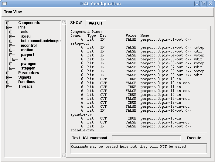
Чтобы просмотреть конфигурацию HAL и проверить состояние контактов и параметров, используйте окно «Конфигурация HAL» в меню «Станок» в AXIS. Чтобы просмотреть статус контакта, откройте вкладку Watch и щелкните каждый контакт, который вы хотите просмотреть, и он будет добавлен в окно просмотра.
1.1. loadrt
The command loadrt loads a real time HAL component. Real time component functions need to be added to a thread to be updated at the rate of the thread. You cannot load a non-realtime component into the realtime space.
loadrt <component> <options>
loadrt mux4 count=1
1.2. addf
The addf command adds a function to a real-time thread. If the StepConf wizard was used to create the configuration, two threads have been created (``base-thread`` and ``servo-thread``).
addf добавляет функцию functname в поток threadname. По умолчанию функции добавляются в том порядке, в котором они находятся в файле. Если position указано, функция добавляется в это место в потоке. Отрицательное значение position указывает положение относительно конца потока. Например, 1 — начало потока, -1 — конец потока, -3 — третий от конца.
Для некоторых функций важно загружать их в определенном порядке, например, функции чтения и записи parport. Имя функции обычно представляет собой имя компонента плюс номер. В следующем примере загружается компонент or2, а show function показывает имя функции or2.
$ halrun
halcmd: loadrt or2
halcmd: show function
Exported Functions:
Owner   CodeAddr  Arg       FP   Users  Name
 00004  f8bc5000  f8f950c8  YES      0   or2.0
You have to add a function from a HAL real time component to a thread to get the function to update at the rate of the thread. Usually there are two threads as shown in this example.
|
Note
|
The |
$ halrun
halcmd: loadrt motmod base_period_nsec=55555 servo_period_nsec=1000000 num_joints=3
halcmd: show thread
Realtime Threads:
     Period  FP     Name               (     Time, Max-Time )
     995976  YES          servo-thread (        0,        0 )
      55332  YES           base-thread (        0,        0 )
-
base-thread (the high-speed thread): This thread handles items that need a fast response, like making step pulses, and reading and writing the parallel port.
-
servo-thread (the slow-speed thread): This thread handles items that can tolerate a slower response, like the motion controller, ClassicLadder, and the motion command handler.
addf <function> <thread>
addf mux4.0 servo-thread
1.3. initf
The initf command registers a function to run once in realtime context, on a dedicated init cycle of the thread before the cyclic function list runs. It is the realtime-thread analogue of addf, intended for one-shot setup that must execute in the realtime task (for example EtherCAT master activation via lcec.activate).
initf adds function functname to the init list of thread threadname. The init list runs once on the first cycle after start, then is drained. The cyclic list begins on the following period. Once the init cycle has run, further initf calls on that thread are rejected. position has the same meaning as in addf.
initf <function> <thread>
initf lcec.activate servo-thread
1.4. loadusr
The command loadusr loads a non-realtime HAL component. Non-realtime programs are their own separate processes, which optionally talk to other HAL components via pins and parameters. You cannot load realtime components into non-realtime space.
Флаги могут быть одним или несколькими из следующих:
| -W |
дождаться готовности компонента. Предполагается, что компонент имеет то же имя, что и первый аргумент команды. |
| -Wn <name> |
дождаться компонента, который будет иметь заданное <name>. Это применимо только в том случае, если у компонента есть опция имени. |
| -w |
дождаться выхода программы |
| -i |
игнорировать возвращаемое значение программы (с -w) |
| -n |
назвать компонент, если это допустимая опция для этого компонента. |
loadusrloadusr <component> <options>
loadusr halui
loadusr -Wn spindle gs2_vfd -n spindleПо-английски это означает loadusr ждет имя шпинделя компонента gs2_vfd имя шпинделя.
1.5. net
The command net creates a connection between a signal and one or more pins. If the signal does not exist net creates the new signal. This replaces the need to use the command newsig. The optional direction arrows <=, => and <=> make it easier to follow the logic when reading a net command line and are not used by the net command. The direction arrows must be separated by a space from the pin names.
netnet signal-name pin-name <optional arrow> <optional second pin-name>
net home-x joint.0.home-sw-in <= parport.0.pin-11-inВ приведенном выше примере home-x — это имя сигнала, joint.0.home-sw-in — это контакт Direction IN, <= — необязательная стрелка направления, а parport.0.pin.-11-in — это контакт «Direction OUT». Это может показаться запутанным, но метки входа и выхода для контакта параллельного порта указывают на физический способ работы контакта, а не на то, как он обрабатывается в HAL.
Контакт может быть подключен к сигналу, если он подчиняется следующим правилам:
-
Контакт IN всегда можно подключить к сигналу.
-
Конакт IO можно подключить, если на сигнале нет контакта OUT.
-
Контакт OUT можно подключить только в том случае, если в сигнале нет других контактов OUT или IO.
Одно и то же signal-name можно использовать в нескольких сетевых командах для подключения дополнительных контактов, если соблюдаются приведенные выше правила.
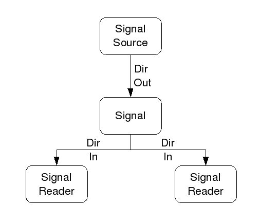
В этом примере показан сигнал xStep с источником stepgen.0.out и двумя считывателями: parport.0.pin-02-out и parport.0.pin-08-out. По сути, значение stepgen.0.out отправляется в сигнал xStep, а затем это значение отправляется в parport.0.pin-02-out и parport.0.pin-08-out.
#   сигнал    источник            получатель          получатель
net xStep stepgen.0.out => parport.0.pin-02-out parport.0.pin-08-out
Поскольку сигнал xStep содержит значение stepgen.0.out (источник), вы можете использовать тот же сигнал снова, чтобы отправить значение другому получателю. Для этого достаточно использовать сигнал с получателями на другой линии.
#   сигнал       получатель2
net xStep => parport.0.pin-06-outКонтакт ввода-вывода, такой как encoder.N.index-enable, может быть считан или установлен в соответствии с разрешением компонента.
1.6. setp
The command setp sets the value of a pin or parameter. The valid values will depend on the type of the pin or parameter. It is an error if the data types do not match.
Некоторые компоненты имеют параметры, которые необходимо настроить перед использованием. При необходимости параметры можно установить перед использованием или во время работы. Вы не можете использовать setp на контакте, подключенном к сигналу.
setpsetp <pin/parameter-name> <value>
setp parport.0.pin-08-out TRUE1.7. sets
The command sets sets the value of a signal.
setssets <signal-name> <value>
net mysignal and2.0.in0 pyvcp.my-led
sets mysignal 1It is an error if:
-
Имя сигнала не существует
-
Если у сигнала уже есть источник
-
Если значение не является правильным типом для сигнала
1.8. unlinkp
The command unlinkp unlinks a pin from the connected signal. If no signal was connected to the pin prior running the command, nothing happens. The unlinkp command is useful for trouble shooting.
unlinkpunlinkp <pin-name>
unlinkp parport.0.pin-02-out1.9. Устаревшие команды
Следующие команды устарели и могут быть удалены из будущих версий. Любая новая конфигурация должна использовать команду net. Эти команды включены, поэтому старые конфигурации по-прежнему будут работать.
1.9.1. linksp (устарела)
Команда linksp создает соединение между сигналом и одним контактом.
linksplinksp <signal-name> <pin-name>
linksp X-step parport.0.pin-02-outThe linksp command has been superseded by the net command.
1.9.2. linkps (устарела)
Команда linkps создает соединение между одним контактом и одним сигналом. Это то же самое, что и linksp, но аргументы обратные.
linkpslinkps <pin-name> <signal-name>
linkps parport.0.pin-02-out X-StepThe linkps command has been superseded by the net command.
1.9.3. newsig
the command newsig creates a new HAL signal by the name <signame> and the data type of <type>. Type must be bool, sint, uint or real. Error if <signame> already exists.
newsignewsig <signame> <type>
newsig Xstep boolДополнительную информацию можно найти в руководстве HAL или на страницах руководства halrun.
2. HAL Data
2.1. bool
A bool value is an on or off.
-
bool values = true or 1 and false or 0 (True, TRUE, true are all valid)
2.2. real
A real is a floating point number. In other words the decimal point can move as needed.
-
real values = a double precision floating point value, with approximately 53 bits of resolution and over 210 (~ 1000) bits of dynamic range.
Дополнительную информацию о числах с плавающей запятой см.:
2.3. sint
An sint number is a whole number that can have a negative or positive value.
-
sint values = integer numbers from -9223372036854775808 to 9223372036854775807
2.4. uint
A uint number is a whole number that is positive only.
-
uint values = integer numbers from 0 to 18446744073709551615
3. HAL файлы
If you used the Stepper Config Wizard to generate your config you will have up to three HAL files in your config directory.
-
«my-mill.hal» (если ваша конфигурация называется «my-mill»). Этот файл загружается первым, и его не следует изменять, если вы использовали Stepper Config Wizard.
-
custom.hal Этот файл загружается следующим, до загрузки ГИП. Здесь вы помещаете свои собственные команды HAL, которые хотите загрузить до загрузки ГИП.
-
custom_postgui.hal Этот файл загружается после загрузки ГИП. Здесь вы помещаете свои собственные команды HAL, которые хотите загрузить после загрузки ГИП. В нем необходимо разместить любые команды HAL, использующие виджеты PyVCP.
4. HAL Параметр
One pin and two parameters are automatically added to each HAL component when it is created. These allow you to scope the execution time of a component.
.time
|
Pin time shows in ns how long it took to execute the function. |
.tmax
|
Parameter tmax is the maximum time in ns it took to execute the function. |
.tmax-increased
|
This parameter is set to true for one cycle if tmax increased. |
tmax — это параметр чтения/записи, поэтому пользователь может установить его равным 0, чтобы избавиться от первой инициализации во время выполнения функции.
5. Основные логические компоненты
HAL contains several real time logic components. Logic components follow a Truth Table that states what the output is for any given input. Typically these are bit manipulators and follow electrical logic gate truth tables.
Дополнительные компоненты см. в HAL Components List или на страницах руководства.
5.1. and2
The and2 component is a two input and-gate. The truth table below shows the output based on each combination of input.
and2 [count=N] | [names=name1[,name2...]]
and2.n
and2.N.in0 (bool, in)
and2.N.in1 (bool, in)
and2.N.out (bool, out)
| in0 | in1 | out |
|---|---|---|
False |
False |
False |
True |
False |
False |
False |
True |
False |
True |
True |
True |
5.2. not
The not component is a boolean inverter.
not [count=n] | [names=name1[,name2...]]
not.all
not.n
not.n.in (bool, in)
not.n.out (bool, out)
| in | out |
|---|---|
True |
False |
False |
True |
5.3. or2
The or2 component is a two input or-gate.
or2[count=n] | [names=name1[,name2...]]
or2.n
or2.n.in0 (bool, in)
or2.n.in1 (bool, in)
or2.n.out (bool, out)
| in0 | in1 | out |
|---|---|---|
True |
False |
True |
True |
True |
True |
False |
True |
True |
False |
False |
False |
5.4. xor2
The xor2 component is a two input xor (exclusive or)-gate.
xor2[count=n] | [names=name1[,name2...]]
xor2.n
xor2.n.in0 (bool, in)
xor2.n.in1 (bool, in)
xor2.n.out (bool, out)
| in0 | in1 | out |
|---|---|---|
True |
False |
True |
True |
True |
False |
False |
True |
True |
False |
False |
False |
6. Примеры логики
.Example using and2
loadrt and2 count=1
addf and2.0 servo-thread
net my-sigin1 and2.0.in0 <= parport.0.pin-11-in
net my-sigin2 and2.0.in1 <= parport.0.pin-12-in
net both-on parport.0.pin-14-out <= and2.0.out
In the above example one copy of and2 is loaded into real time space and added to the servo thread. Next pin-11 of the parallel port is connected to the in0 input of the and gate. Next pin-12 is connected to the in1 input of the and gate. Last we connect the and2 output to the parallel port pin-14. So following the truth table for and2 if pin 11 and pin 12 are on then the output pin 14 will be on.
7. Компоненты преобразования
7.1. weighted_sum
The weighted sum converts a group of booleans into an integer. The conversion is the sum of the weights of the booleans present plus any offset. It’s similar to binary coded decimal but with more options. The hold input interrupts the input processing, so that the sum value no longer changes.
weighted_sumloadrt weighted_sum wsum_sizes=size[,size,...]Creates groups of ``weighted_sum``s, each with the given number of input booleans (size).
Чтобы обновить weighted_sum, process_wsums должен быть прикреплен к потоку.
process_wsums в поток сервоприводаaddf process_wsums servo-threadПри этом обновляется компонент weighted_sum.
In the following example, a copy of the AXIS HAL configuration window, bools 0 and 2 are TRUE, they have no offset. The weight (weight) of bool 0 is 1, that of bool 2 is 4, so the sum is 5.
| Владелец | Type | Dir | Value | Имя |
|---|---|---|---|---|
10 |
bool |
In |
TRUE |
|
10 |
sint |
I/O |
1 |
|
10 |
bool |
In |
FALSE |
|
10 |
sint |
I/O |
2 |
|
10 |
bool |
In |
TRUE |
|
10 |
sint |
I/O |
4 |
|
10 |
bool |
In |
FALSE |
|
10 |
sint |
I/O |
8 |
|
10 |
bool |
In |
FALSE |
|
10 |
sint |
I/O |
0 |
|
10 |
sint |
Out |
5 |
|