1. Preamble
Except where noted, this guide assumes the user is using the latest version of QtPlasmaC. Version history can be seen by visiting this link which will show the latest available version. The installed QtPlasmaC version is displayed in the title bar. See Update QtPlasmaC for information on updating QtPlasmaC.
2. License
QtPlasmaC and all of its related software are released under GPLv2.
3. Einführung
QtPlasmaC is a GUI for plasma cutting which utilises the plasmac component for controlling a plasma table from LinuxCNC v2.9 or later using the Debian Buster or similar distribution.
The QtPlasmaC GUI supports up to five axes and uses the QtVCP infrastructure provided with LinuxCNC.
The standard theme is based on a design by user "pinder" on the LinuxCNC Forum and the colors are able to be changed by the user.
The QtPlasmaC GUI will run on any hardware that is supported by LinuxCNC v2.9 or later provided there are enough hardware I/O pins to fulfill the requirements of a plasma configuration.
There are three available formats:
-
16:9 with a minimum resolution of 1366 x 768
-
9:16 with a minimum resolution of 768 x 1366
-
4:3 with a minimum resolution of 1024 x 768
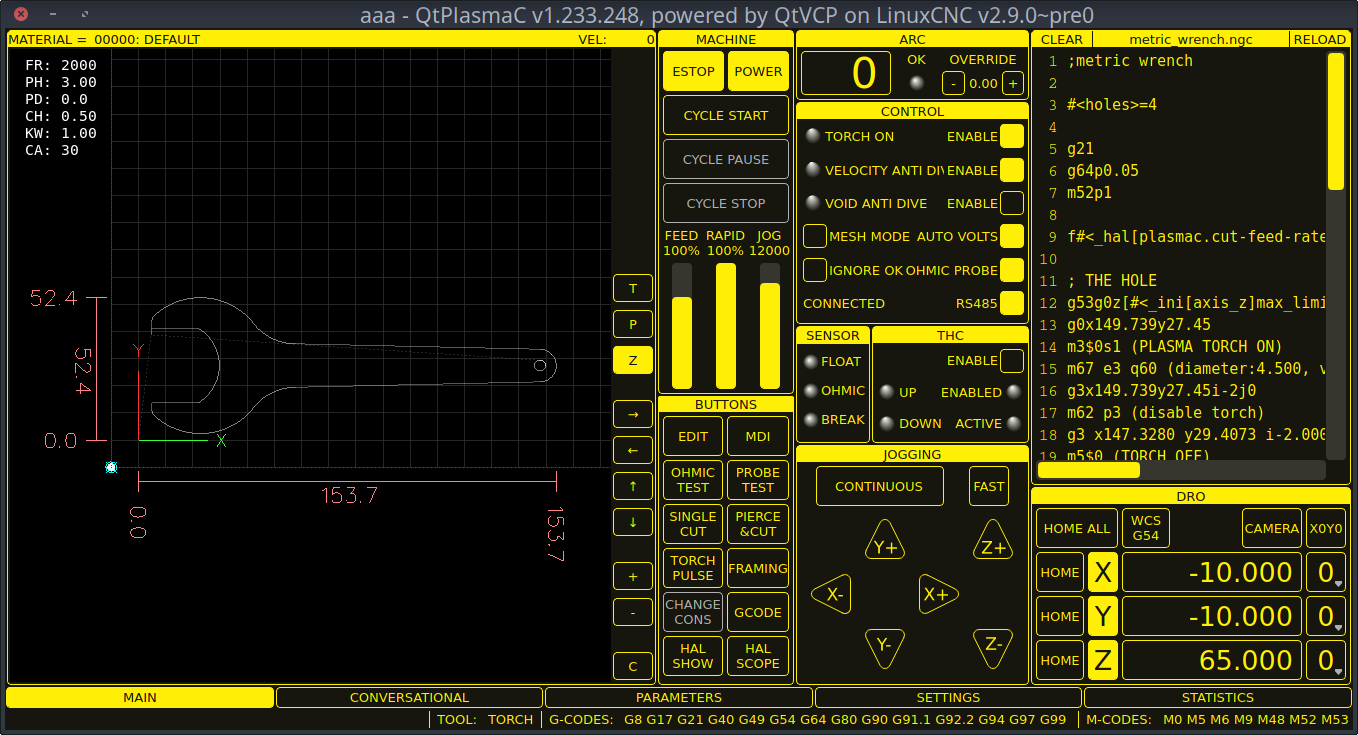
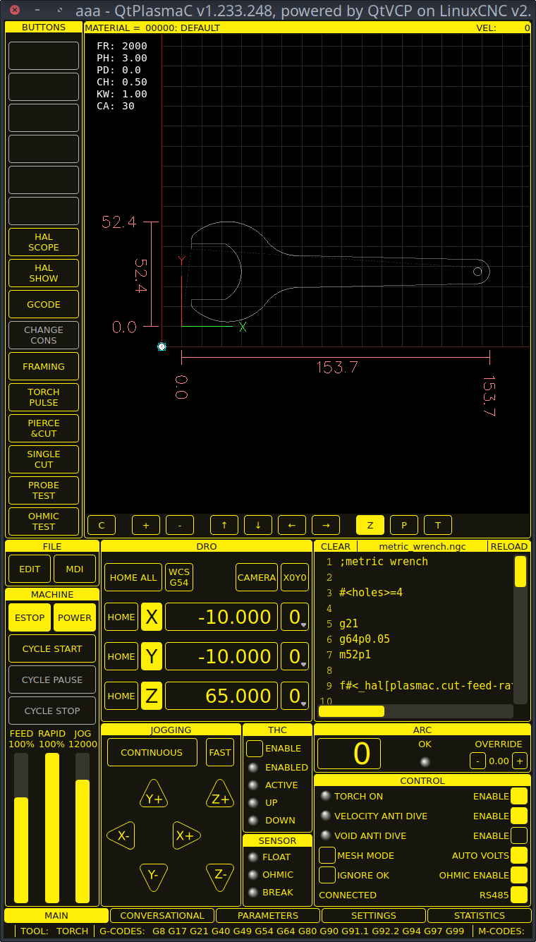
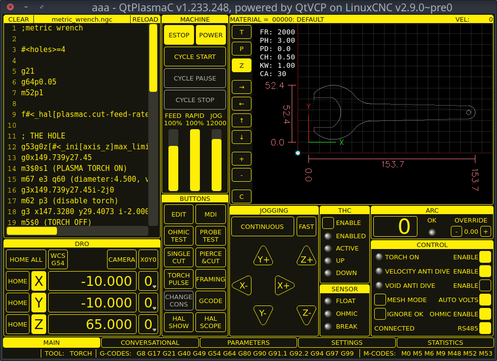
Screenshot examples of QtPlasmaC are below:
4. LinuxCNC installieren
Die bevorzugte Methode zur Installation von LinuxCNC ist über ein ISO-Image, wie unten beschrieben.
|
Anmerkung
|
Es ist möglich, LinuxCNC auf einer Vielzahl von Linux-Distributionen zu installieren und auszuführen, was jedoch den Rahmen dieses Benutzerhandbuchs sprengen würde. Wenn der Benutzer möchte eine Linux-Distribution andere als die empfohlenen zu installieren, müssen sie zunächst ihre bevorzugte Linux-Distribution zu installieren und dann installieren LinuxCNC v2.9 oder höher zusammen mit allen erforderlichen Abhängigkeiten. |
4.1. Wenn der Benutzer kein Linux installiert hat
Installation instructions are available from here.
Following these instructions will yield a machine with the current stable branch of LinuxCNC (v2.9) on Debian 12 (Bookworm).
4.2. Package Installation (Buildbot) If The User Has Linux on Debian 12 (Bookworm)
Follow the instructions from the Updating LinuxCNC on Debian Bookworm section from here.
4.3. Package Installation (Buildbot) If The User Has Linux on Debian 11 (Bullseye) or Debian 10 (Buster)
A package installation (Buildbot) uses prebuilt packages from the LinuxCNC Buildbot.
Add the GPG keys and add the repository to the sources list to suit the Debian version.
The below stanza would add the 2.9 Bullseye repository.
deb http://buildbot2.highlab.com/ bookworm 2.9-uspace4.4. Run In Place Installation If The User Has Linux Installed
A run in place installation runs LinuxCNC from a locally compiled version usually located at ~/linuxcnc-dev, instructions for building a run in place installation are available from here.
5. Erstellen einer QtPlasmaC Konfiguration
Vor der Erstellung einer QtPlasmaC-Konfiguration ist es wichtig, dass der Benutzer die verfügbaren Betriebsmodi sowie die für einen erfolgreichen Plasmabetrieb erforderlichen E/As genau kennt.
5.1. Modi
QtPlasmaC erfordert die Auswahl eines der folgenden drei Betriebsmodi:
| Modus | Beschreibung |
|---|---|
0 |
Verwendet einen externen Lichtbogenspannungseingang, um sowohl die Lichtbogenspannung (für die Brennerhöhensteuerung) als auch den Lichtbogen-OK zu berechnen. |
1 |
Uses an external arc voltage input to calculate Arc Voltage (for Torch Height Control). |
2 |
Uses an external Arc OK input for Arc OK. |
|
Wichtig
|
If the plasma power source has an Arc OK (Transfer) output then it is recommended to use that for Arc OK rather than the soft (calculated) Arc OK provided by mode 0. It may also be possible to use a reed relay as an alternative method to establish an Arc OK signal when the power source does not provide one. |
|
Anmerkung
|
Für die Feinabstimmung von Mode 0 Ark OK siehe Tuning Mode 0 Arc OK im Abschnitt Erweiterte Themen des Handbuchs. |
5.2. Verfügbare I/Os
|
Anmerkung
|
Dieser Abschnitt befasst sich nur mit den für QtPlasmaC erforderlichen Hardware-E/As. Die Anforderungen an die Basismaschine, wie Endschalter, Home-Schalter usw., kommen noch hinzu. |
| Name | Modi | Beschreibung |
|---|---|---|
Arc Voltage |
0, 1 |
Analog input; optional. |
Bogen OK |
1, 2 |
Digital input; optional. |
Float Switch |
0, 1, 2 |
Digital input; optional, see info below table: |
Ohmic Probe |
0, 1, 2 |
Digital input; optional, see info below table: |
Ohmic Probe Enable |
0, 1, 2 |
Digital output; optional, see info below table: |
Breakaway Switch |
0, 1, 2 |
Digital input; optional, see info below table: |
Brenner ein (engl. torch on) |
0, 1, 2 |
Digital output; required. |
Move Up |
2 |
Digital input; optional. |
Move Down |
2 |
Digital input; optional. |
Scribe Arming |
0, 1, 2 |
Digital output; optional. |
Scribe On |
0, 1, 2 |
Digital output; optional. |
Laser On |
0, 1, 2 |
Digital output; optional. |
Only one of either Float Switch or Ohmic Probe is required. If both are used then Float Switch will be a fallback if Ohmic Probe is not sensed.
If Ohmic Probe is used then Ohmic Probe Enable is required to be checked on the QtPlasmaC GUI.
Breakaway Switch is not mandatory because the Float Switch is treated the same as a breakaway when not probing. If they are two separate switches, and there are not enough inputs on the breakout board, they could be combined and connected as a Float Switch.
|
Anmerkung
|
The minimum I/O requirement for a QtPlasmaC configuration to function are: Arc Voltage input OR Arc OK input, Float Switch input, and Torch On output. To reiterate, in this case QtPlasmaC will treat the float switch as a breakaway switch when it is not probing. |
5.3. Recommended Settings:
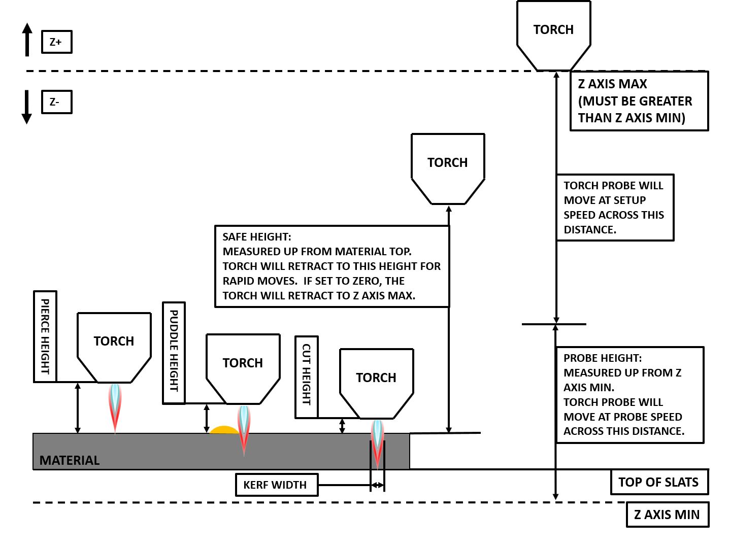
Refer to the Heights Diagram diagram for a visual representation of the terms below.
-
[AXIS_Z] MIN_LIMIT should be just below top of the slats with allowances for float_switch_travel and over travel tolerance. For example, if the user’s float switch takes 4 mm (0.157") to activate then set the Z minimum to 5 mm (0.2") plus an allowance for overrun (either calculated using the equation below or allow 5 mm (0.2") below the lowest slat).
-
[AXIS_Z] MAX_LIMIT should be the highest the user wants the Z axis to travel (it must not be lower than Z HOME_OFFSET).
-
[AXIS_Z] HOME should be set to be approximately 5 mm-10 mm (0.2"-0.4") below the maximum limit.
-
Floating Head - it is recommended that a floating head be used and that it has enough movement to allow for overrun during probing. Overrun can be calculated using the following formula:
o = 0.5 * a * (v / a)^2where: o = overrun, a = acceleration in units/s2 and v = velocity in units/s.
Metric example: given a Z axis MAX_ACCELERATION of 600 mm/s2 and MAX_VELOCITY of 60 mm/s, the overrun would be 3 mm.
Imperial example: given a Z axis MAX_ACCELERATION of 24 in/s2 and MAX_VELOCITY of 2.4 in/s, the overrun would be 0.12 in.
On machines that will utilize an ohmic probe as the primary method of probing, it is highly recommended to install a switch on the floating head as a backup means of stopping Z motion in the event of ohmic probe failure due to dirty surfaces.
5.4. Configuring
LinuxCNC provides two configuration wizards which can be used to build a machine configuration. The choice of these wizards is dependent on the hardware used to control the machine.
If the user wishes to use a Run In Place installation then prior to running one of the following commands they will need to run the following command from a terminal:
source ~/linuxcnc-dev/scripts/rip-environmentIf using a Package installation then no additional action is required.
If using a parallel port, use the StepConf wizard by running the stepconf command in a terminal window or launching it using the Application -> CNC -> StepConf Wizard desktop menu entry.
If using a Mesa Electronics board, use the PnCconf wizard by running the pncconf command in a terminal window or launching it using the Application -> CNC -> PnCConf Wizard desktop menu entry.
If using a Pico Systems board, this LinuxCNC forum thread may be helpful.
Die gerätespezifischen Einstellungen werden hier nicht beschrieben, sondern sind in der Dokumentation des jeweiligen Konfigurationsassistenten nachzulesen, der verwendet wird.
There are LinuxCNC forum sections available for these wizards:
Füllen Sie die erforderlichen Einträge entsprechend der Konfiguration der Maschinenverdrahtung/Breakout-Platine aus.
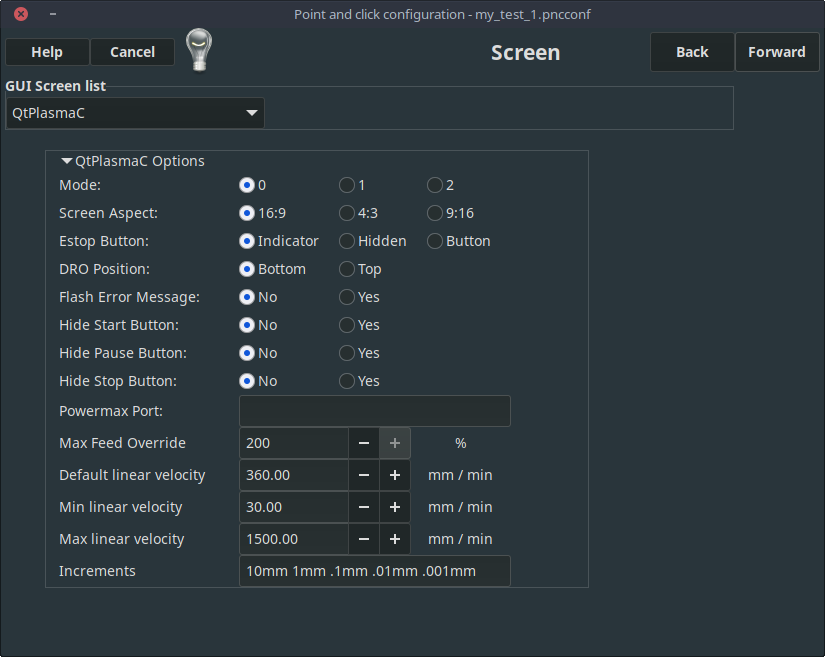
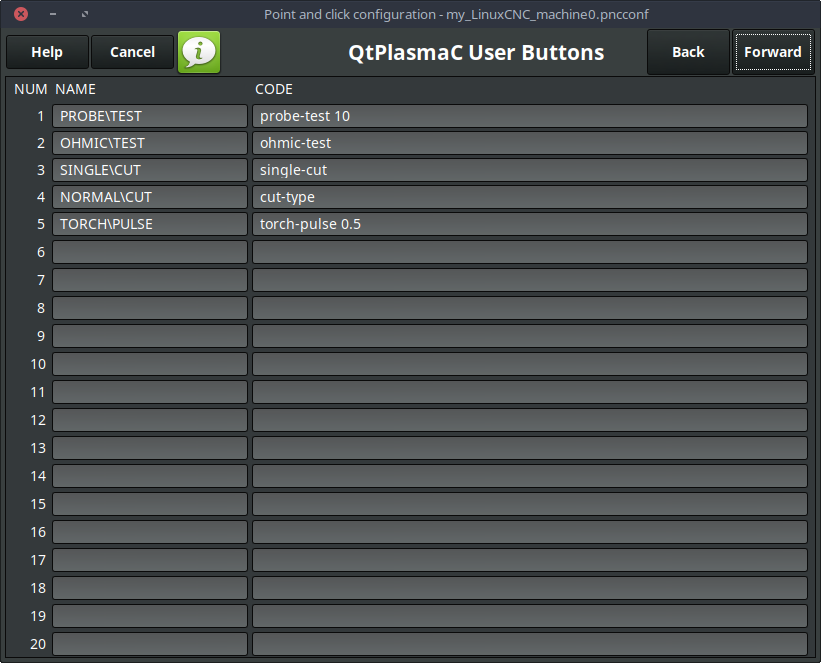
QtPlasmaC adds two pages to the LinuxCNC configuration wizards for QtPlasmaC specific parameters, the two pages are QtPlasmaC options and User Buttons. Complete each of the wizards QtPlasmaC page to suit the machine that is being configured and the user button requirements.
Note that PnCconf options allow user selection of Feed Override, Linear Velocity, and Jog Increments, whereas in StepConf these are automatically calculated and set.
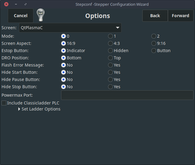
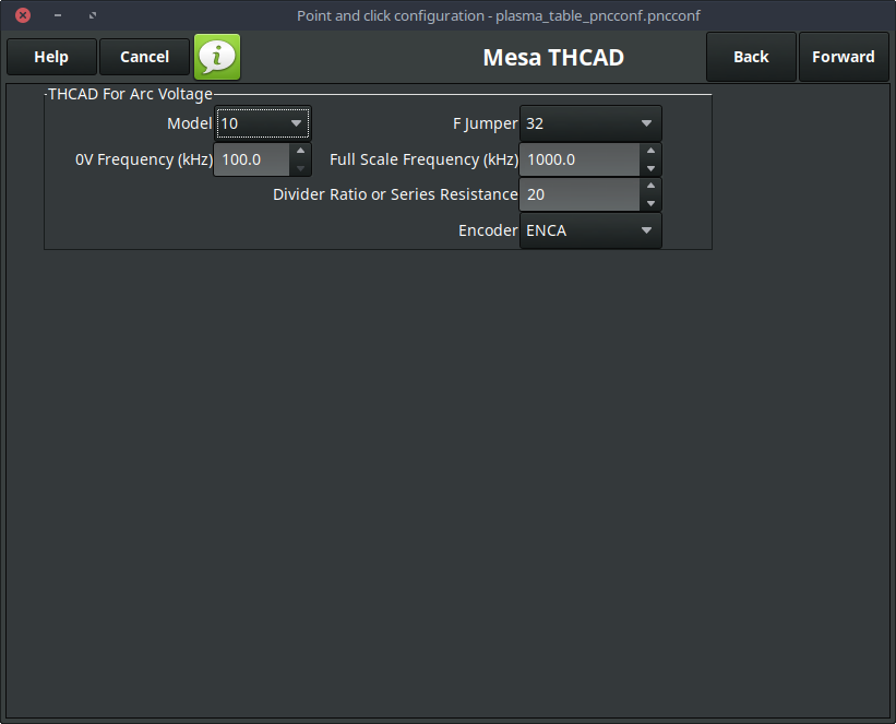
The THCAD screen will only appear if a Plasma Encoder is selected in the card screen. The the dedicated section on Mesa THCAD for more information.
When the configuration is complete, the wizard will save a copy of the configuration that may be loaded and edited at a later time, a working QtPlasmaC configuration will be created in the following directory: ~/linuxcnc/configs/<machine_name>.
The way the newly created QtPlasmaC configuration can be run from the terminal command line slightly differs depending the way LinuxCNC was installed:
Für eine Paketinstallation (Buildbot):
linuxcnc ~/linuxcnc/configs/_<machine_name>_/_<machine_name>_.iniFor a run in place installation:
~/linuxcnc-dev/scripts/linuxcnc ~/linuxcnc/configs/_<machine_name>_/_<machine_name>_.iniNach dem Ausführen des obigen Befehls sollte LinuxCNC mit der QtPlasmaC GUI sichtbar sein.
|
Wichtig
|
BEVOR DER BENUTZER FORTFÄHRT, SOLLTE ER IN DER LAGE SEIN, DIE MASCHINE IN DIE AUSGANGSPOSITION ZU BRINGEN, JEDE ACHSE AUF NULL ZU STELLEN, ALLE ACHSEN BIS ZU DEN WEICHEN GRENZWERTEN ZU VERFAHREN, OHNE DASS ES ZU EINEM ABSTURZ KOMMT, UND G-CODE-TESTPROGRAMME OHNE FEHLER AUSZUFÜHREN. |
NUR WENN diese Kriterien erfüllt sind, sollte der Benutzer mit der Ersteinrichtung von QtPlasmaC fortfahren.
|
Anmerkung
|
Es ist möglich, eine Simulationskonfiguration mit StepConf zu erstellen, aber es ist nicht möglich, Tandemgelenke in der Simulationskonfiguration zu haben. |
5.5. Qt-Abhängigkeitsfehler
Wenn beim Versuch, die QtPlasmaC-Konfiguration auszuführen, Fehler in Bezug auf Qt-Abhängigkeiten auftreten, muss der Benutzer möglicherweise das QtVCP-Installationsskript ausführen, um diese Probleme zu beheben.
Geben Sie für eine Paketinstallation (Buildbot) den folgenden Befehl in einem Terminalfenster ein:
/usr/lib/python3/dist-packages/qtvcp/designer/install_scriptGeben Sie für eine "run in place"-Installation den folgenden Befehl in ein Terminalfenster ein:
~/linuxcnc-dev/lib/python/qtvcp/designer/install_script5.6. Erstmalige Einrichtung
Das folgende Höhendiagramm soll dem Benutzer helfen, die verschiedenen Höhen beim Plasmaschneiden und deren Messung zu veranschaulichen:
Click on the Parameters Tab to view the CONFIGURATION section which shows the user settable parameters. It is necessary to ensure every one of these settings is tailored to the machine.
To set the Z axis DRO relative to the Z axis MINIMUM_LIMIT, the user should perform the following steps. It is important to understand that in QtPlasmaC, touching off the Z axis DRO has no effect on the Z axis position while running a G-code program. These steps simply allow the user to more easily set the probe height as after performing the steps, the displayed Z axis DRO value will be relative to Z axis MINIMUM_LIMIT.
|
Anmerkung
|
The user should be familiar with the recommended Z Axis Settings. |
-
Referenzierung der Z-Achse.
-
Vergewissern Sie sich, dass sich nichts unter dem Brenner befindet, dann bewegen Sie die Z-Achse nach unten, bis sie am MINIMUM_LIMIT der Z-Achse anhält, und klicken Sie dann auf die 0 neben der Z-Achsen-Anzeige, um die Z-Achse mit der ausgewählten Z-Achse auf Nullpunktverschiebung zu setzen. Dieser Schritt dient nur dazu, dem Benutzer eine einfachere Visualisierung und Einstellung der Sondenhöhe zu ermöglichen - dieser Wert wird vom MINIMUM_LIMIT der Z-Achse aufwärts gemessen.
-
Erneute Referenzierfahrt der Z-Achse.
Wenn das Gerät mit einem Schwimmerschalter ausgestattet ist, muss der Benutzer den Offset im Abschnitt KONFIGURATION auf der Registerkarte PARAMETER einstellen. Dies geschieht durch Ausführen eines "Probe Test"-Zyklus.
-
Überprüfen Sie, ob die Sondengeschwindigkeit und die Sondenhöhe im Abschnitt CONFIGURATION auf der Registerkarte PARAMETERS korrekt sind. QtPlasmaC kann mit der vollen Geschwindigkeit der Z-Achse tasten, solange die Maschine genügend Bewegung im Schwimmerschalter hat, um einen eventuellen Überlauf aufzufangen. Wenn die Maschine dafür geeignet ist, kann der Benutzer die Sondenhöhe auf einen Wert in der Nähe des Z-Achsen-Minimums einstellen und die gesamte Abtastung mit voller Geschwindigkeit durchführen.
-
Wenn die Maschine noch keine Referenzierfahrt durchführt und nicht in der Ausgangsposition ist, dann führen Sie die Referenzierfahrt durch.
-
Legen Sie etwas Material auf die Latten unter den Brenner.
-
Drücken Sie die Taste PROBE TEST.
-
The Z axis will probe down, find the material then move up to the specified Pierce Height as set by the currently selected material. The torch will wait in this position for the time set in the <machine_name>.prefs file. The default probe test hold time is 10 seconds, this value may be edited in the <machine_name>.prefs file. After this the torch will return to the starting height.
-
Measure the distance between the material and the tip of the torch while the torch is waiting at Pierce Height.
-
If the measurement is greater than the Pierce Height of the currently selected material, then reduce the "Float Travel" in the CONFIGURATION section of the PARAMETERS tab by the difference between the measured value and the specified value. If the measurement is less than Pierce Height of the currently selected material, then increase the "Float Travel" in the CONFIGURATION section of the PARAMETERS tab by the difference between the specified value and the measured value.
-
After the adjustments to the "Float Travel" have been made, repeat the process from #4 above until the measured distance between the material and the torch tip matches the Pierce Height of the currently selected material.
-
If the table has a laser or camera for sheet alignment, a scribe, or uses offset probing then the required offsets need to be applied by following the procedure described in Peripheral Offsets.
-
CONGRATULATIONS! The user should now have a working QtPlasmaC Configuration.
|
Anmerkung
|
If the amount of time between the torch contacting the material and when the torch moves up and comes to rest at the Pierce Height seems excessive, see the probing section for a possible solution. |
|
Wichtig
|
IF USING A Mesa Electronics THCAD THEN THE Voltage Scale VALUE WAS OBTAINED MATHEMATICALLY. IF THE USER INTENDS TO USE CUT VOLTAGES FROM A MANUFACTURE’S CUT CHART THEN IT WOULD BE ADVISABLE TO DO MEASUREMENTS OF ACTUAL VOLTAGES AND FINE TUNE THE Voltage Scale AND Voltage Offset. |
|
Warnung
|
PLASMA CUTTING VOLTAGES CAN BE LETHAL, IF THE USER IS NOT EXPERIENCED IN DOING THESE MEASUREMENTS GET SOME QUALIFIED HELP. |
6. Migrating to QtPlasmac From PlasmaC (AXIS or GMOCCAPY)
There are two methods available to get from a working PlasmaC configuration to a new QtPlasmaC configuration. These methods assume the user is on LinuxCNC v2.9 or later, QtVCP is installed, and all dependency requirements are satisfied.
If there are Qt dependency errors, the user should run the QtVCP install script.
6.1. Quick Method
A quick method to move to QtPlasmaC from PlasmaC (loaded on top of either AXIS or GMOCCAPY) is to use the plasmac2qt conversion program, which will attempt to create a new QtPlasmaC configuration from an existing PlasmaC INI file. This program will convert the user’s parameters, settings, and materials from the previous PlasmaC configuration and create a new QtPlasmaC configuration directory in the ~/linuxcnc/configs directory.
This methods will keep the original PlasmaC config as a backup with _plasmac and a time stamp appended to the directory name.
To run the plasmac2qt conversion program, use the following instructions:
For a package installation (Buildbot) enter the following line in a terminal window:
qtplasmac-plasmac2qtFor a run in place installation enter the following lines in terminal window:
source ~/linuxcnc-dev/scripts/rip-environment
qtplasmac-plasmac2qt
The following screen will be displayed:
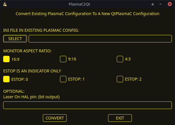
| Field | Beschreibung | Beispiele |
|---|---|---|
INI-DATEI IN VORHANDENER PLASMAC-KONFIGURATION |
This is the INI file of the PlasmaC config that requires migrating. |
<machine_name>.ini |
BILDSCHIRM-SEITENVERHÄLTNIS |
This is the aspect ratio format for the GUI. |
16:9 |
ESTOP (engl. für Notaus) |
Selects the required E-stop type based on the following criteria: |
ESTOP:1 |
Lassen Sie dieses Feld leer, wenn es nicht verwendet/erforderlich ist.
| Field | Beschreibung | Beispiele |
|---|---|---|
Laser On HAL-Pins |
Schalten Sie ein Laserfadenkreuz für die Bogenausrichtung ein. |
Parallel Port Example: parport.0.pin-16-out |
Nachdem Sie die entsprechenden Eingaben gemacht haben, drücken Sie CONVERT.
|
Anmerkung
|
This method will not change any existing debounce components to the new dbounce component. If the user wishes to change to the new dbounce component then the New Base Config method should be used for migration. |
6.2. Neue Basis-Konfigurationsmethode
This method to move to QtPlasmaC from PlasmaC (loaded on top of either AXIS or GMOCCAPY) is to use a configuration wizard to create a new configuration. This method then allows changing of the base machine configuration at a later date via the configuration wizard, provided that the base INI and base HAL files have not been edited.
Bei dieser Methode muss der Benutzer alle HAL-Pins notieren, die in der vorhandenen Konfiguration verwendet werden, damit sie in den Konfigurationsassistenten eingegeben werden können. Alle benutzerdefinierten HAL-Befehle müssen ebenfalls notiert und entweder der Datei custom.hal oder der Datei custom_postgui.hal, die vom Konfigurationsassistenten erstellt wird, manuell hinzugefügt werden.
After using the wizard, the user can then run a conversion program (cfg2prefs) to convert the parameters, settings, and materials from the previous PlasmaC configuration to the new QtPlasmaC configuration. This tool should be used immediately after the user has created a new QtPlasmaC configuration.
Prior to running this conversion program, it is mandatory that the user have both an existing PlasmaC configuration and a new QtPlasmaC configuration. This program will overwrite the existing QtPlasmaC preferences and materials files, and should be used with caution if it is not being run on a new QtPlasmaC configuration.
The program will create a time-stamped backup of the original preferences file and the existing materials file (if it exists).
It will read the existing <machine_name>config.cfg, <machine_name>_run.cfg, <machine_name>_wizards.cfg, and plasmac_stats.var files and write them to an existing _<machine_name>.prefs file. It will also copy the <machine_name>_material.cfg file to the existing QtPlasmaC configuration.
Um das Konvertierungsprogramm cfg2prefs auszuführen, folgen Sie den folgenden Anweisungen:
For a package installation (Buildbot) enter the following line in a terminal window:
qtplasmac-cfg2prefsFor a run in place installation enter the following lines in terminal window:
source ~/linuxcnc-dev/scripts/rip-environment
qtplasmac-cfg2prefs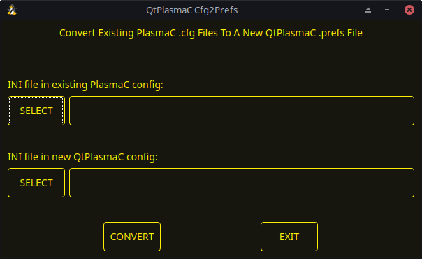
qtplasmac-cfg2prefsSelect the INI file of the old PlasmaC configuration, select the INI file of the new QtPlasmaC configuration, then press CONVERT.
7. Other QtPlasmaC Setup Considerations
7.1. Lowpass Filter
The plasmac HAL component has a built in lowpass filter that if used is applied to the plasmac.arc-voltage-in input pin to filter any noise that could cause erroneous voltage readings. The lowpass filter should only be used after using Halscope to determine the required frequency and whether the amplitude of the noise is large enough to cause any issues. For most plasma machines lowpass is not required and should not be used unless it is required.
The HAL pin assigned to this filter is plasmac.lowpass-frequency and is set to 0 (disabled) by default. To apply a lowpass filter to the arc-voltage, the user would edit the following entry in the custom.hal file in the machine’s configuration directory to add the appropriate cutoff frequency as measured in Hertz (Hz).
Zum Beispiel:
setp plasmac.lowpass-frequency 100
The above example would give a cutoff frequency of 100Hz.
7.2. Contact Bounce
Contact bounce from mechanical relays, switches, or external interference may cause some inconsistent behavior of the following switches:
-
Float Switch
-
Ohmic Probe
-
Breakaway Switch
-
Arc OK (for modes 1 & 2)
Due to the fact that the software is capable of sampling rates faster than the contact bounce period, it is possible that the software may see contact bounce as several changes in input states occurring in a very small time period, and incorrectly interpret this as a very quick on-off of the input. One method of mitigating contact bounce is to "debounce" the input. To summarize debounce, it requires the input state to be stable at the opposite state of the output state for consecutive delay periods before changing the state of the output.
Debounce delay periods can be changed by editing the appropriate debounce value in the custom.hal file in the <machine_name> config directory.
Each increment of delay adds one servo thread cycle to the debounce time. For example: given a servo thread period of 1000000 (measured in nano seconds), a debounce delay of 5 would equate to 5000000 ns, or 5 ms.
For the Float and Ohmic switches this equates to a 0.001 mm (0.00004") increase in the probed height result.
It is recommended to keep the debounce values as low as possible while still achieving consistent results. Using Halscope to plot the inputs is a good way to establish the correct value.
For QtPlasmaC installations, debounce is achieved by using the HAL dbounce component which is a later alternative to the original debounce component. This new version allows for the loading and naming of individual debounce instances and is compatible with Twopass HAL file processing.
All four signals above have an individual debounce component so the debounce periods can be catered individually to each input. Any changes made to these values in the custom.hal file will not be overwritten by later updates of QtPlasmaC.
The default delay for all four inputs is five servo thread periods. In most cases this value will work quite well. If any of the inputs do not use mechanical switches, it may be possible to either reduce or remove the delay for those inputs.
If debounce is required for other equipment like home or limit switches etc. then more dbounce components may added in any of the HAL files without any regard to the signals listed here.
7.3. Contact Load
Mechanical relays and switches usually require a minimum current passing through the contacts for reliable operation. This current varies with the material that the contacts in the device are made from.
Depending on the specified minimum contact current and the current drawn by the input device there may be a need to provide a method to increase the current through the contacts.
Most relays using gold contacts will not require any additional current for reliable operation.
There are two different methods available to provide this minimum current if it is required:
-
A 0.1 μF film capacitor placed across the contacts.
-
A 1200 Ω 1 W resistor across the load (see calculations below).
Schematics are shown at contact load schematics.
More information on contact switching load can be seen on page VI of the finder General Technical Information document.
If using a Mesa card, the input resistance of a 7I96 is 4700 Ω (symbol R)(always consult the product manual associated with the revision being used as these values sometimes vary between revisions), giving a contact current of 5.1 mA (symbol I) assuming a supply voltage (symbol U) of 24 V (I = U/R)
[In the US, the letter V is commonly used as a symbol (Voltage) and as a unit (Volt).]
.
As an example, the typical relay used in a Hypertherm Powermax 65 plasma cutter (TE T77S1D10-24) requires a minimum contact load of 100 mA @ 5 VDC which will dissipate 0.5 W (P = I * V). If using a 24 VDC power supply this would then equate to a minimum current of 20.8 mA. Because there is less current drawn by the Mesa input than is required by the relay there needs to be an increase in the current.
The resistance can be calculated using R = Us / (Im - Ii) where:
-
R = berechneter Widerstand
-
Us = supply voltage
-
Im = minimum current required
-
Ii = input current
Using a 7I96 with an input current of 5.1 mA gives a calculated value of 1529 Ω ( = 24 V / (.0208 - .0051) A). This could then be rounded down to a commonly available 1500 Ω resistor, giving a small safety margin.
The power dissipation can by calculated using P = Us2 / Rs where:
-
P = Leistung
-
Us = supply voltage
-
Rs = selected resistance
This gives a value of 0.38 W. This could then be rounded up to 1 W, giving a good safety margin. The final selection would be a 1500 Ω 1 W resistor.
7.4. Desktop-Starthilfe
If a link to the launch the configuration was not created when creating the config, the user could create a desktop launcher to the config by right clicking on the desktop and selecting Create Launcher or similar. This will bring up a dialog box to create a launcher. Give the icon a nice short name, enter anything for the command and click OK.
Nachdem der Launcher auf dem Desktop erscheint, klicken Sie mit der rechten Maustaste darauf und bearbeiten Sie ihn mit dem Editor Ihrer Wahl. Bearbeiten Sie die Datei so, dass sie ungefähr so aussieht:
[Desktop Entry]
Comment=
Terminal=false
Name=LinuxCNC
Exec=sh -c "linuxcnc $HOME/linuxcnc/configs/<machine_name>/<machine_name>.ini"
Type=Application
Icon=/usr/share/pixmaps/linuxcncicon.png
Wenn der Benutzer ein Terminalfenster hinter dem GUI-Fenster öffnen möchte, ändern Sie die Terminal-Zeile in:
Terminal=trueDie Anzeige eines Terminals kann für Fehler- und Informationsmeldungen nützlich sein.
7.5. QtPlasmaC Dateien
Nach einer erfolgreichen QtPlasmaC-Installation werden die folgenden Dateien im Konfigurationsverzeichnis angelegt:
| Filename | Funktion |
|---|---|
<machine_name>.ini |
Configuration file for the machine. |
<machine_name>.hal |
HAL for the machine. |
<machine_name>.prefs |
Configuration file for QtPlasmaC specific parameters and preferences. |
custom.hal |
HAL file for user customization. |
custom_postgui.hal |
HAL file for user customization which is run after the GUI has initialized. |
shutdown.hal |
HAL file which is run during the shutdown sequence. |
tool.tbl |
Tool table used to store offset information for additional tools (scribe, etc.) used by the QtPlasmaC configuration. |
qtplasmac |
Link to the directory containing common qtplasmac support files. |
backup |
Directory for backups of config files. |
|
Anmerkung
|
<machine_name> is whatever name the user entered into the "Machine Name" field of the configuration wizard program. |
|
Anmerkung
|
Custom commands are allowed in custom.hal and the custom_postgui.hal files as they are not overwritten during updates. |
After running a new configuration for the first time the following files will be created in the configuration directory:
| Filename | Funktion |
|---|---|
<machine_name>_material.cfg |
File for storing the material settings from the MATERIAL section of the PARAMETERS Tab. |
update_log.txt |
File for storing log of major updates. |
qtvcp.prefs |
File containing the QtVCP preferences. |
qtplasmac.qss |
File storing the stylesheet for the currently loaded session of QtPlasmaC. |
|
Anmerkung
|
The configuration files (<machine_name>.ini and <machine_name>.hal) that are created by configuration wizard are notated to explain the requirements to aid in manual manipulation of these configurations. They may be edited with any text editor. |
|
Anmerkung
|
The <machine_name>.prefs file is plain text and may be edited with any text editor. |
7.6. INI File
QtPlasmaC has some specific <machine_name>.ini file variables as follows:
These variables are mandatory.
PROGRAM_EXTENSION = .ngc,.nc,.tap G-code File (*.ngc, *.nc, *.tap)
ngc               = qtplasmac_gcode
nc                = qtplasmac_gcode
tap               = qtplasmac_gcode
[RS274NGC] Section
These variables are mandatory.
RS274NGC_STARTUP_CODE = G21 G40 G49 G80 G90 G92.1 G94 G97 M52P1
SUBROUTINE_PATH       = ./:../../nc_files
USER_M_PATH           = ./:../../nc_files
|
Anmerkung
|
for a imperial config replace G21 above with G20. |
|
Anmerkung
|
both the above paths show the minimum requirements. |
|
Wichtig
|
SEE PATH TOLERANCE FOR RS274NGC_STARTUP_CODE INFORMATION RELATED TO G64. |
[HAL] Section
These variables are mandatory.
HALUI           = halui (required)
HALFILE         = _<machine_name>_.hal (the machine HAL file)
HALFILE         = plasmac.tcl (the standard QtPlasmaC HAL file )
HALFILE         = custom.hal (Users custom HAL commands)
POSTGUI_HALFILE = postgui_call_list.hal (required)
SHUTDOWN        = shutdown.hal (shutdown HAL commands)
|
Anmerkung
|
The user could place custom HAL commands in the custom.hal file as this file is not overwritten by QtPlasmaC updates. |
[DISPLAY] Section
This variable is mandatory.
DISPLAY = qtvcp qtplasmac      (use 16:9 resolution)
        = qtvcp qtplasmac_9x16 (use 9:16 resolution)
        = qtvcp qtplasmac_4x3  (use 4:3 resolution)
There are multiple QtVCP options that are described here: QtVCP INI Settings
For example the following would start a 16:9 resolution QtPlasmaC screen in full screen mode:
DISPLAY = qtvcp -f qtplasmac
[TRAJ] Section
This variable is mandatory.
SPINDLES = 3
[AXIS_X] Section
These variables are mandatory.
MAX_VELOCITY     = double the value in the corresponding joint
MAX_ACCELERATION = double the value in the corresponding joint
OFFSET_AV_RATIO  = 0.5
[AXIS_Y] Section
These variables are mandatory.
MAX_VELOCITY     = double the value in the corresponding joint
MAX_ACCELERATION = double the value in the corresponding joint
OFFSET_AV_RATIO  = 0.5
[AXIS_Z] Section
These variables are mandatory.
MIN_LIMIT = knapp unterhalb der Oberkante der Tischlatten
MAX_VELOCITY = das Doppelte des Wertes des entsprechenden Gelenks
MAX_ACCELERATION = das Doppelte des Wertes des entsprechenden Gelenks
OFFSET_AV_RATIO = 0,5
|
Anmerkung
|
QtPlasmaC verwendet das LinuxCNC-Feature "Externe Offsets" für alle Z-Achsen-Bewegungen und für das Bewegen der X- und/oder Y-Achse für einen Verschleißteilwechsel im Pausenzustand. Für weitere Informationen über diese Funktion lesen Sie bitte External Axis Offsets in der LinuxCNC Dokumentation. |
8. QtPlasmaC GUI Überblick
Die folgenden Abschnitte geben einen allgemeinen Überblick über das Layout von QtPlasmaC.
8.1. Beenden von QtPlasmaC
Das Beenden oder Herunterfahren von QtPlasmaC erfolgt entweder durch:
-
Klicken Sie auf die Schaltfläche zum Herunterfahren des Fensters in der Titelleiste des Fensters
-
Drücken Sie lange auf die Taste POWER auf der Haupt-Registerkarte (engl. main).
A shutdown warning can be displayed on every shutdown by checking the Exit Warning checkbox on the SETTINGS Tab.
8.2. HAUPT (engl. main)-Registerkarte (engl. tab)
Screenshot example of the QtPlasmaC MAIN Tab in 16:9 aspect ratio:
Einige Funktionen/Merkmale werden nur für bestimmte Modi verwendet und werden nicht angezeigt, wenn sie für den gewählten QtPlasmaC-Modus nicht erforderlich sind.
| Name | Beschreibung |
|---|---|
Material |
In diesem Bereich kann die obere Kopfzeile angeklickt werden, um ein Dropdown-Menü zu öffnen. Es wird verwendet, um die aktuellen Materialschnittparameter manuell auszuwählen. Wenn in der Materialdatei keine Materialien vorhanden sind, wird nur das Standardmaterial angezeigt. |
Geschw.: |
Hier wird der tatsächliche Schnittvorschub angezeigt, mit dem sich der Tisch bewegt. |
FR: |
If "View Material" is selected on the SETTINGS Tab, this displays the currently selected material’s Feed Rate. |
PH: |
If "View Material" is selected on the SETTINGS Tab, this displays the currently selected material’s Pierce Height. |
PD: |
If "View Material" is selected on the SETTINGS Tab, this displays the currently selected material’s Pierce Delay. |
CH: |
If "View Material" is selected on the SETTINGS Tab, this displays the currently selected material’s Cut Height. |
CA: |
If "View Material" is selected on the SETTINGS Tab, and RS485 communications are enabled, this displays the currently selected material’s Cut Amperage. |
T |
Diese Schaltfläche ändert die preview in eine vollständige Tabellenansicht von oben nach unten. |
P |
Diese Schaltfläche ändert die preview in eine isometrische Ansicht. |
Z |
Diese Schaltfläche ändert die preview in eine Ansicht von oben nach unten. |
→ |
Diese Schaltfläche verschiebt die Voransicht (engl. preview) nach rechts. |
← |
Diese Schaltfläche schwenkt die Voransicht nach links. |
↑ |
Diese Schaltfläche schwenkt die Voransicht nach oben. |
↓ |
Diese Schaltfläche schwenkt die Voransicht nach unten. |
+ |
Diese Schaltfläche vergrößert die Voransicht. |
- |
Diese Schaltfläche vergrößert die Voransicht. |
C |
Diese Schaltfläche löscht die Live-Darstellung. |
| Name | Beschreibung |
|---|---|
ESTOP (engl. für Notaus) |
Setting Estop type = 0 in the [GUI_OPTIONS] section of the <machine_name>.prefs file, will change this button to an indicator of the hardware E-stop’s status only. This is the default behavior. |
POWER (engl. für Leistung oder Strom) |
Diese Schaltfläche schaltet die GUI ein und erlaubt QtPlasmaC/LinuxCNC die Steuerung der Hardware. |
ZYKLUSSTART |
Mit dieser Button startet den Zyklus für jede geladene G-Code-Datei. |
ZYKLUSPAUSE |
Mit diesem Button wird der Zyklus für jede geladene G-Code-Datei angehalten. |
ZYKLUS STOP (engl. cycle stop) |
This button stops any actively running or paused cycle. |
FEED |
This slider overrides the feed rate for all feed moves. |
RAPID |
This slider overrides the rapid rate for all rapid moves. |
JOG |
This slider sets the jog rate. |
The Button Panel contains buttons useful for the operation of the machine.
The EDIT and MDI buttons are permanent, all other buttons are user programmable in the <machine_name>.prefs file.
See custom user buttons for detailed information on custom user buttons.
| Name | Beschreibung |
|---|---|
EDIT |
This button opens a G-code editor for the currently loaded program. |
MDI |
This button places QtPlasmaC into Manual Data Input (MDI) mode which will display the MDI HISTORY and an entry box over top of the G-code window. |
OHMIC TEST |
This button will enable the Ohmic Probe Enable output signal and if the Ohmic Probe input is sensed, the LED indicator in the SENSOR Panel will light. |
PROBE TEST |
This button will initiate a Probe Test. |
SINGLE CUT |
This button will show the dialog box to start an automatic Single Cut. |
NORMAL CUT |
This button will toggle between Cut Types (NORMAL CUT and PIERCE ONLY). |
TORCH PULSE |
This button will initiate a Torch Pulse. |
| Name | Modi | Beschreibung |
|---|---|---|
Arc Voltage |
0, 1 |
Displays the actual arc voltage. |
OK |
0, 1, 2 |
Indicates the status of the Arc OK signal. |
+ |
0, 1 |
Each press of this button will raise the target voltage by the THC Threshold voltage (The distance changed will be Height Per Volt * THC Threshold voltage). |
- |
0, 1 |
Each press of this button will lower the target voltage by the THC Threshold voltage (The distance changed will be Height Per Volt * THC Threshold voltage). |
OVERRIDE |
0, 1 |
Clicking this label will return any voltage override to 0.00. |
| Name | Modi | Beschreibung |
|---|---|---|
TORCH ON |
0, 1, 2 |
Indicates the status of the Torch On output signal. |
TORCH ON ENABLE |
0, 1, 2 |
This box toggles between Enabling and Disabling the torch. |
VELOCITY ANTI DIVE |
0, 1, 2 |
Indicates that the THC is locked at the current height due to the cut velocity falling below the Velocity Anti Dive (VAD) Threshold percentage set on the PARAMETERS Tab. |
VELOCITY ANTI DIVE ENABLE |
0, 1, 2 |
This box toggles between Enabling and Disabling VELOCITY ANTI DIVE. |
VOID ANTI DIVE |
0, 1 |
Indicates that the THC is locked due to a void being sensed. |
VOID ANTI DIVE ENABLE |
0, 1 |
This box toggles between Enabling and Disabling VOID ANTI DIVE. |
MESH MODE |
0, 1, 2 |
This box will enable or disable Mesh Mode for the cutting of expanded metal. This check box may be enabled or disabled at any time during normal cutting. |
AUTO VOLTS |
0, 1 |
This box will enable or disable Auto Volts. |
IGNORE OK |
0, 1, 2 |
This box will determine if QtPlasmaC ignores the Arc OK signal.
This check box may be enabled or disabled at any time during normal cutting.
Additionally this mode may be enabled or disabled via proper M codes in a running program. |
OHMIC PROBE |
0, 1, 2 |
Dieses Feld aktiviert oder deaktiviert den Eingang der ohmschen Sonde. |
RS485 |
0, 1, 2 |
This box will enable or disable the communications to a PowerMax.
This button is only visible if a PM_PORT option is configured in the |
Status |
0, 1, 2 |
When PowerMax communications are enabled, this will display one of the following: |
| Name | Beschreibung |
|---|---|
FLOAT |
Indicates that the float switch is activated. |
OHMIC |
Indicates that the probe has sensed the material. |
BREAK |
Indicates that the torch breakaway sensor is activated. |
| Name | Beschreibung |
|---|---|
ENABLE (AKTIVIEREN) |
This box determines whether the THC will be enabled or disabled during a cut. |
ENABLED |
This LED indicates whether the THC is enabled or disabled. |
ACTIVE |
This LED indicates that the THC is actively controlling the Z axis. |
UP |
This LED indicates that the THC is commanding the Z axis to raise. |
DOWN |
This LED indicates that the THC is commanding the Z axis to lower. |
|
Anmerkung
|
JOGGING. During Paused Motion, this section will become CUT RECOVERY |
| Name | Beschreibung |
|---|---|
CONTINUOUS |
This drop down button will change the jog increment. Options are determined by the values in the [DISPLAY] section of the <machine_name>.ini file and begin with the label "INCREMENTS =". |
FAST |
This button will toggle between FAST which is the default linear velocity in the <machine_name>.ini file or SLOW which is 10% of the default value. |
Y+ |
This button moves the Y axis in the positive direction. |
Y- |
This button moves the Y axis in the negative direction. |
X+ |
This button moves the X axis in the positive direction. |
X- |
This button moves the X axis in the negative direction. |
Z+ |
This button moves the Z axis in the positive direction. |
Z- |
This button moves the Z axis in the negative direction. |
|
Anmerkung
|
CUT RECOVERY During Paused Motion, this section will be shown on top of the JOGGING panel. The following section will cover each button encountered in this panel. Please see CUT RECOVERY for a detailed description of the cut recovery functionality. |
| Name | Beschreibung |
|---|---|
PAUSED MOTION FEED SLIDER |
In the event of a paused program, this interface allows X/Y motion to follow the programmed path in the reverse or forward direction. |
FEED |
This displays the paused motion feed rate. |
REV |
In the event of a paused program, this button will move the machine in reverse along the programmed path until it reaches the last M3 command that was either executed or that QtPlasmaC was attempting to execute before the program became paused. |
FWD |
In the event of a paused program, this button will move the machine forward along the programmed path indefinitely until the program’s end, skipping over M3 commands. |
CANCEL MOVE |
This button will cancel any Cut Recovery movement that was made, and return the torch to the position the Cut Recovery movement was initiated. |
MOVE x.xxx |
This displays the amount of travel that will be incurred with each press of an arrow key, in the direction the arrow key was pressed. |
DIRECTIONAL ARROWS |
These buttons will move the torch in the direction indicated by a distance of one Kerf Width (of the currently selected material) per press. |
| Name | Beschreibung |
|---|---|
CLEAR |
This button will clear the currently opened program. |
OPEN |
Diese Schaltfläche öffnet ein DATEI-ÖFFNEN-Panel über dem VORSCHAU-FENSTER. |
NEU LADEN |
Diese Schaltfläche lädt die aktuell geladene G-Code-Datei neu. |
| Name | Beschreibung |
|---|---|
HOME ALL |
This button will home all of the axes in the order set by HOME_SEQUENCE in the <machine_name>.ini file. |
WCS G54 |
This drop down button will change the current work offset. |
CAMERA |
This button will display a CAMVIEW panel on top of the PREVIEW WINDOW and will allow the user to set an origin with or without rotation. See the CAMERA section for detailed instructions. |
LASER |
This button will allow the user to use a laser to set an origin with or without rotation. See the LASER section for detailed instructions. |
X0 Y0 |
This button will set the current position to X0 Y0. |
HOME [AXIS] |
This button will home the corresponding axis. |
0 [AXIS] |
This drop down button will display the following options: |
8.3. Preview Views
The QtPlasmaC preview screen has the ability to be switched between different views and displays, as well as zooming in and out, and panning horizontally and vertically.
When QtPlasmaC is first started, the Z (top down) view will be selected as the default view for a loaded G-code file, but the full table view will be displayed.
When a G-code file is loaded, the display will change to the selected view.
Whenever there is no G-code file loaded, the full table will automatically be displayed irrespective of which view is currently selected (the highlighted button representing the currently selected view will not change).
If a full table is displayed due to no G-code file being loaded and the user wishes to change the view orientation, then pressing either Z or P will change the display to the newly selected view. If the user then wishes to display the full table while maintaining the currently selected view as the default view for a loaded G-code file, then pressing CLEAR will achieve this and allow the selected view orientation to prevail the next time a G-code file is loaded.
8.4. CONVERSATIONAL Tab
Screenshot example of the QtPlasmaC CONVERSATIONAL Tab in 16:9 aspect ratio:
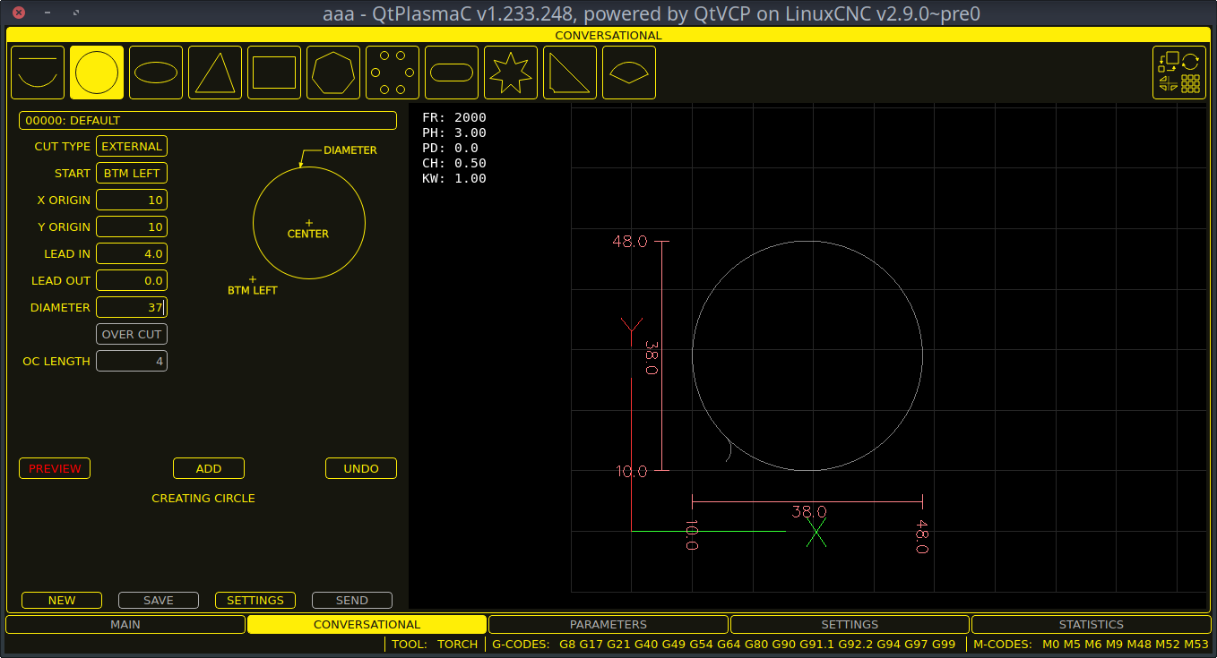
The CONVERSATIONAL Tab enables the user to quickly program various simple shapes for quick cutting without the need for CAM software.
See Conversational Shape Library for detailed information on the Conversational feature.
It is possible to hide this tab so the conversational feature cannot be used by an operator. This may be achieved either by wiring the pin to a physical key-switch or similar or it may also be set in a HAL file using the following command:
setp qtplasmac.conv_disable 1
8.5. PARAMETERS Tab
Screenshot example of the QtPlasmaC PARAMETERS Tab in 16:9 aspect ratio:
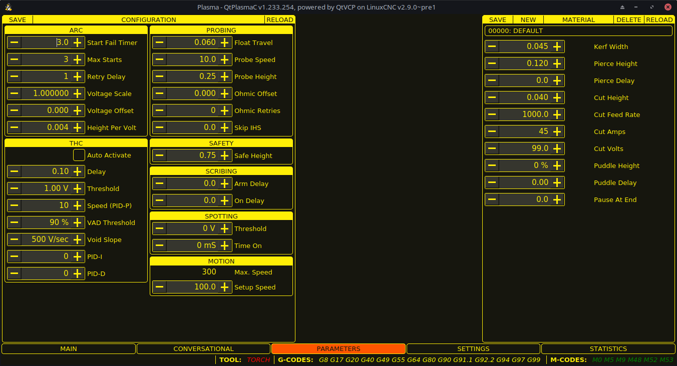
Einige Funktionen/Merkmale werden nur für bestimmte Modi verwendet und werden nicht angezeigt, wenn sie für den gewählten QtPlasmaC-Modus nicht erforderlich sind.
This tab is used to display configuration parameters that are modified infrequently.
It is possible to hide this tab so machine settings cannot be modified by unauthorized personnel. This may be achieved either by wiring the pin to a physical key-switch or similar or it may also be set in a HAL file using the following command:
setp qtplasmac.param_disable 1
| Name | Modi | Beschreibung |
|---|---|---|
Start Fail Timer |
0, 1, 2 |
This sets the amount of time (in seconds) QtPlasmaC will wait between commanding a "Torch On" and receiving an Arc OK signal before timing out and displaying an error message. |
Max. Starts |
0, 1, 2 |
This sets the number of times QtPlasmaC will attempt to start the arc. |
Retry Delay |
0, 1, 2 |
This sets the time (in seconds) between an arc failure and another arc start attempt. |
Voltage Scale |
0, 1 |
This sets the arc voltage input scale and is used to display the correct arc voltage. |
Voltage Offset |
0, 1 |
This sets the arc voltage offset and is used to display zero volts when there is zero arc voltage input. |
Height Per Volt |
0, 1, 2 |
This sets the distance the torch would need to move to change the arc voltage by one volt. |
OK High Volts |
0 |
This sets the voltage threshold below which Arc OK signal is valid. |
OK Low Volts |
0 |
This sets the voltage threshold above which the Arc OK signal is valid. |
|
Anmerkung
|
When setting the OK Low Volts and OK High Volts in Mode 0, the cut voltage of a stable arc must be greater than the OK Low Volts value but lower than the OK High Volts value for QtPlasmaC to receive a valid Arc OK signal. To further clarify, to have a valid Arc OK, the arc voltage must fall between the two limits. |
| Name | Beschreibung |
|---|---|
Float Travel |
This sets the amount of travel the float switch moves before completing the float switch circuit. This distance can be measured by using the Probe Test button, and the method described in Initial Setup. |
Sonden-Geschwindigkeit |
This sets the speed at which the torch will probe to find the material after it moves to the Probe Height. |
Probe Height |
This sets the height above the Z axis minimum limit that Probe Speed begins. Refer to the Heights Diagram diagram for a visual representation. |
Ohmic Offset |
This sets the distance above the material the torch will should go after a successful ohmic probe. It is mainly used to compensate for high probing speeds. |
Ohmic Retries |
This sets the number of times QtPlasmaC will retry a failed ohmic probe before falling back to the float switch for material detection. |
Skip IHS |
This sets the distance threshold used to determine if an Initial Height Sense (probe) can be skipped for the current cut, see IHS Skip. |
|
Anmerkung
|
If the amount of time between the torch contacting the material and when the torch moves up and comes to rest at the Pierce Height seems excessive, see the probing section for a possible solution. |
| Name | Beschreibung |
|---|---|
Safe Height |
This sets the height above the material that the torch will retract to before executing rapid moves. |
| Name | Beschreibung |
|---|---|
Arm Delay |
This sets the delay (in seconds) from the time the scribe command is received to the activation of the scribe. This allows the scribe to reach surface of the material before activating the scribe. |
On Delay |
This sets the delay (in seconds) to allow the scribe mechanism to start before beginning motion. |
| Name | Beschreibung |
|---|---|
Threshold |
This sets the arc voltage at which the delay timer will begin. |
Time On |
This sets the length of time (in milliseconds) the torch is on after threshold voltage is reached. |
| Name | Beschreibung |
|---|---|
Max. Geschwindigkeit |
Displays the maximum velocity the Z axis is capable of (this is controlled by the <machine_name>.ini file). |
Setup Speed |
The Z axis velocity for setup moves (movements to Probe Height, Pierce Height, Cut Height, etc.). |
|
Anmerkung
|
Setup Speed has no effect on THC speed which is capable of the velocity displayed in the Max. Speed field. |
Two methods of THC activation are available and are selected with the Auto Activation checkbutton. Both methods begin their calculations when the current velocity of the torch matches the cut feed rate specified for the selected material:
-
Delay Activation (the default) is selected when Auto Activation is unchecked. This method uses a time delay set with the Delay parameter.
-
Auto Activation is selected when Auto Activation is checked. This method determines that the arc voltage is stable by using the Sample Counts and Sample Threshold parameters.
| Name | Modi | Beschreibung |
|---|---|---|
Delay |
0, 1, 2 |
This sets the delay (in seconds) measured from the time the Arc OK signal is received until Torch Height Controller (THC) activates. This is only available when Auto THC is not enabled. |
Sample Counts |
0, 1 |
This sets the number of consecutive arc voltage readings within THC Sample Threshold required to activate the Torch Height Controller (THC). This is only available when Auto THC is enabled. |
Sample Threshold |
0, 1 |
This sets the maximum voltage deviation allowed for THC Sample Counts. This is only available when Auto THC is enabled. |
Threshold |
0, 1 |
This sets the voltage variation allowed from the target voltage before for THC makes movements to correct the torch height. |
Speed (PID-P) |
0, 1, 2 |
This sets the Proportional gain for the THC PID loop. This roughly equates to how quickly the THC attempts to correct changes in height. |
VAD Threshold |
0, 1, 2 |
(Velocity Anti Dive) This sets the percentage of the current cut feed rate the machine can slow to before locking the THC to prevent torch dive. |
Void Slope |
0, 1 |
(Void Anti Dive) This sets the size of the change in cut voltage per seconds necessary to lock the THC to prevent torch dive (higher values need greater voltage change to lock THC). |
PID-I |
0, 1 |
This sets the Integral gain for the THC PID loop. Integral gain is associated with the sum of errors in the system over time and is not always needed. |
PID-D |
0, 1 |
This sets the Derivative gain for the THC PID loop. Derivative gain works to dampen the system and reduce over correction oscillations and is not always needed. |
|
Anmerkung
|
PID loop tuning is a complicated process and is outside the scope of this User Guide. There are many sources of information available to assist with understanding and tuning PID loops. If the THC is not making corrections fast enough, it is recommended to increase the P gain in small increments until the system operates favorably. Large P gain adjustments can result in over correction and oscillations. |
The SAVE button will save the currently displayed parameters to the <machine_name>.prefs file.
The RELOAD button will reload all the parameters from the <machine_name>.prefs file.
| Name | Beschreibung |
|---|---|
Material |
The top drop down menu is used to manually select the current material cut parameters. If there are no materials in the material file then only the default material will be displayed. |
Kerf Width |
This sets the kerf width for the currently selected material. Refer to the Heights Diagram diagram for a visual representation. |
Pierce Height |
This sets the pierce height for the currently selected material. Refer to the Heights Diagram diagram for a visual representation. |
Pierce Delay |
This sets the pierce delay (in seconds) for the currently selected material. |
Cut Height |
This sets the cut height for the currently selected material. Refer to the Heights Diagram diagram for a visual representation. |
Cut Feed Rate |
This sets the cut feed rate for the currently selected material. |
Cut Amps |
This sets the cut amperage for the currently selected material. |
Cut Volts |
This sets the cut voltage for the currently selected material. |
Puddle Height |
Expressed as a percentage of Pierce Height, this sets the Puddle Jump height for the currently selected material. |
Puddle Delay |
This sets the amount of time (in seconds) the torch will stay at the P-Jump Height before proceeding to Cut Height. |
Pause At End |
This sets the amount of time (in seconds) the torch will stay on at the end of the cut before proceeding with the M5 command to turn off and raise the torch. For more information see Pause At End Of Cut. |
Gas Pressure |
This sets the gas pressure for the currently selected material. |
Cut Mode |
This sets the cut mode for the currently selected material. |
|
Anmerkung
|
See the thick materials section for more information on puddle jump. |
The SAVE button will save the current material set to the <machine_name>_material.cfg file.
The RELOAD button will reload the material set from the <machine_name>_material.cfg file.
The NEW button will allow a new material to be added to the material file. The user will be prompted for a material number and a material name, all other parameters will be read from the currently selected material. Once entered, QtPlasmaC will reload the material file and display the new material. The Cut Parameters for the new material will then need to be adjusted and saved.
The DELETE this button is used to delete a material. After pressing it, the user will be prompted for a material number to be deleted, and prompted again to ensure the user is sure. After deletion, the material file will be reloaded and the drop down list will display the default material.
8.6. SETTINGS Tab
Screenshot example of the QtPlasmaC SETTINGS Tab in 16:9 aspect ratio:
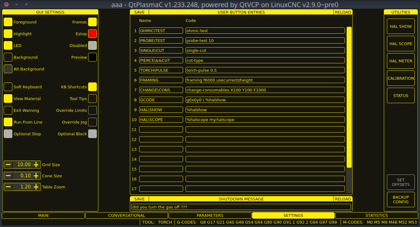
Diese Registerkarte wird verwendet, um GUI-Konfigurationsparameter, Schaltflächentext und Herunterfahrtext anzuzeigen, die selten geändert werden, sowie einige Dienstprogrammschaltflächen.
It is possible to hide this tab so machine settings cannot be modified by unauthorized personnel. This may be achieved either by wiring the pin to a physical key-switch or similar or it may also be set in a HAL file using the following command:
setp qtplasmac.settings_disable 1
This section shows parameters that effect the GUI appearance and GUI behaviors.
To return any of the color changes to their default values, see the Returning To The Default Styling section.
| Name | Beschreibung |
|---|---|
Foreground |
This button allows the user to change the color of the GUI Foreground. |
Highlight |
This button allows the user to change the color of the GUI Highlight. |
LED |
This button allows the user to change the color of the GUI LED. |
Background |
This button allows the user to change the color of the GUI Background. |
Alt Background |
This button allows the user to change the color of the GUI Alternate Background. |
Frames |
This button allows the user to change the color of the GUI Frames. |
Estop |
This button allows the user to change the color of the GUI Estop. |
Disabled |
This button allows the user to change the color of the GUI’s Disabled features. |
Vorschau |
This button allows the user to change the color of the GUI Preview Window Background. |
Soft Keyboard |
This radio button allows the user to enable or disable the soft touchscreen keyboard. |
KB Shortcuts |
This radio button allows the user to enable or disable Keyboard Shortcuts within the GUI (such as keyboard jogging). |
View Material |
This radio button allows the user to enable or disable the addition of a visual reference showing key material cut settings to the Preview Windows of the MAIN and CONVERSATIONAL tabs. |
Exit Warning |
This radio button allows the user to enable or disable whether a warning will always be displayed during shutdown. |
Optional Stop |
This radio button allows the user to enable or disable whether or not a running program will pause at an M1 command. |
Run From Line |
This radio button allows the user to enable or disable Run From Line. If enabled, the user can click on a line of G-code and have the program start from that line. |
Grenzwerte überschreiten |
This radio button allows the user to temporarily Override the input from a Limit Switch in the event the limit switch becomes tripped during operation. This button can only be clicked when a limit switch is tripped. |
Override Jog |
This radio button will also allow jogging while jogging is inhibited due to a float switch, breakaway switch, or ohmic probe activation. This button can only be clicked when a jog is inhibited. |
Optional Block |
This radio button allows the user to enable or disable whether or not lines starting with "/" will be skipped if present in a running program. |
Grid Size |
This allows a user to change the size of the grid in the Preview Window on the MAIN Tab. Grid size of 0.0 will disable the grid. |
Cone Size |
This allows a user to change the size of the cone (which represents the current tool) in the Preview Window on the MAIN Tab. |
Table Zoom |
This allows a user to change the default zoom level for the top down full table view in the Preview Window on the MAIN Tab. |
This section shows the text that appears on the Custom User Buttons as well as the code associated with the user button. User buttons may be changed and the new settings used without restarting LinuxCNC.
The text and/or code may be edited at any time and will be loaded ready for use if the SAVE button is clicked.
Deleting the Name and Code text will cause that user button to be hidden if the SAVE button is clicked.
To return all the Name and Code text to their last saved values press the RELOAD button.
| Name | Code |
|---|---|
The text that is displayed on the button |
The code that is run when the button is pressed. |
|
Anmerkung
|
There are 20 user buttons available but not all may be displayed depending on the window size. |
Dieser Abschnitt zeigt den Text, der im Dialogfeld zum Herunterfahren angezeigt wird, wenn die Option Exit-Warnung aktiviert ist.
The text may be edited at any time and will be loaded ready for use if the SAVE button is clicked.
To return the EXIT WARNING MESSAGE text to the last saved value press the RELOAD button.
Some standard LinuxCNC utilities are provided as an aid in the diagnosis of issues that may arise:
In addition the following two QtPlasmaC specific utilities are provided:
Die Schaltfläche OFFSETS SETZEN wird verwendet, wenn der Tisch mit einem Laser oder einer Kamera zur Bogenausrichtung (engl. sheet alignment), einem Ritzgerät (engl. scribe) oder einem Offset-Taster ausgestattet ist. Die erforderlichen Offsets für diese Peripheriegeräte müssen nach dem unter << peripheral-offsets, Peripherie-Offsets>> beschriebenen Verfahren angewendet werden.
The BACKUP CONFIG button will create a complete machine configuration backup for archiving or to aid in fault diagnosis. A compressed backup of the machine configuration will be saved in the user’s Linux home directory. The file name will be <machine_name><version><date>_<time>.tar.gz, where <machine_name> is the machine name entered in the configuration wizard, <version> is the current QtPlasmaC version the user is on, <date> is the current date (YY-MM-DD), and <time> is the current time (HH-MM-SS).
Prior to the backup being made, the machine log will be saved to a file in the configuration directory named machine_log_<date>_<time>.txt where <date> and <time> are formatted as described above. This file along with up to five previous machine logs will also be included in the backup.
These files are not required by QtPlasmaC and are safe to delete at any time.
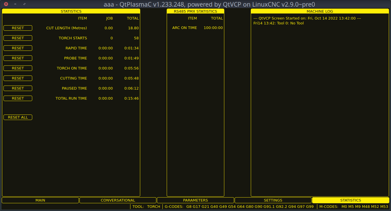
8.7. STATISTICS Tab
The STATISTICS Tab provides statistics to allow for the tracking of consumable wear and job run times. These statistics are shown for the current job as well as the running total. Previous job statistics are reset once the next program is run. The total values may be reset either individually by clicking the corresponding "RESET" button, or they may all be reset together by clicking "RESET ALL".
The RS485 PMX STATISTICS panel will be only be displayed if the user has Hypertherm PowerMax communications and a valid RS485 connection to the PowerMax is established. This panel will show the ARC ON TIME for the PowerMax in hh:mm:ss format.
The MACHINE LOG is also displayed on the STATISTICS Tab, this log will display any errors and/or important information that occurs during the current LinuxCNC session. If the user makes a backup of the configuration from the SETTINGS Tab then the machine log is also included in the backup.
9. Using QtPlasmaC
Once QtPlasmaC is successfully installed, no Z axis motion is required to be part of the G-code cut program. In fact, if any Z axis references are present in the cut program, the standard QtPlasmaC configuration will remove them during the program loading process.
For reliable use of QtPlasmaC the user should NOT use any Z axis offsets other than the coordinate system offsets (G54-G59.3).
QtPlasmaC fügt am Anfang jedes G-Code-Programms automatisch eine Zeile G-Code ein, um die Z-Achse auf die richtige Höhe zu bringen.
Version Information - QtPlasmaC will display versioning information in the title of the main window. The information will be displayed as followed "QtPlasmaC vN.XXX.YYY - powered by QtVCP on LinuxCNC vZ.Z.Z" where N is the version of QtPlasmaC, XXX is the version of the HAL component (PlasmaC.comp), YYY is the GUI version, and Z.Z.Z is the version of LinuxCNC.
9.1. Einheitensysteme
All settings and parameters in QtPlasmaC are required to be in the same units as specified in the INI file, being either metric or imperial.
If the user is attempting to run a G-code file that is in the "other" units system then all parameters including the material file parameters are still required to be in the native machines units. Any further conversions necessary to run the G-code file will be handled automatically by the G-code filter program.
For example: If a user had a metric machine and wished to run a G-code file that was set up to cut 1/4" thick material using imperial units (inch - G20) then the user with the metric machine would need to ensure that either the material number in the G-code file was set to the corresponding metric material to be cut, or that a new material is created with the correct metric parameters for the metric material to be cut. If the metric user wanted to cut the G-code file using imperial material, then the new material parameters would need to be converted from imperial units to metric when they are entered.
9.2. Präambel und Postambel Codes
The following stanzas are the minimum recommended codes to include in the preamble and postamble of any G-code file to be run by QtPlasmaC:
Metrisch:
G21 G40 G49 G64p0.1 G80 G90 G92.1 G94 G97
Imperial:
G20 G40 G49 G64p0.004 G80 G90 G92.1 G94 G97
Eine ausführliche Erläuterung der einzelnen G-Codes finden Sie unter dem Link docs:../gcode/g-code.html[hier].
Beachten Sie, dass in diesem Benutzerhandbuch mehrere zusätzliche Empfehlungen für Codes gegeben werden, die je nach den vom Benutzer gewünschten Funktionen sowohl in der Präambel als auch in der Postambel hinzugefügt werden sollten.
9.3. Obligatorische Codes
Aside from the preamble code, postamble code, and X/Y motion code, the only mandatory G-code syntax for QtPlasmaC to run a G-code program using a torch for cutting is M3 $0 S1 to begin a cut and M5 $0 to end a cut.
For backwards compatibility it is permissible to use M3 S1 in lieu of M3 $0 S1 to begin a cutting job and M5 in lieu of M5 $0 to end a cutting job. Note, that this applies to cutting jobs only, for scribe and spotting jobs the $n tool identifier is mandatory.
9.4. Koordinaten
See recommended Z axis settings.
Each time LinuxCNC (QtPlasmaC) is started Joint homing is required. This allows LinuxCNC (QtPlasmaC) to establish the known coordinates of each axis and set the soft limits to the values specified in the <machine_name>.ini file in order to prevent the machine from crashing into a hard stop during normal use.
If the machine does not have home switches then the user needs to ensure that all axes are at the home coordinates specified in the <machine_name>.ini file before homing.
Wenn die Maschine mit Referenzfahrtschaltern ausgestattet ist, fährt sie zu den angegebenen Referenzpunktkoordinaten, wenn die Gelenke referenziert werden.
Depending on the machine’s configuration there will either be a Home All button or each axis will need to be homed individually. Use the appropriate button/buttons to home the machine.
As mentioned in the Initial Setup section, it is recommended that the first time QtPlasmaC is used that the user ensure there is nothing below the torch then jog the Z axis down until it stops at the Z axis MINIMUM_LIMIT then click the 0 next to the Z axis DRO to Touch Off with the Z axis selected to set the Z axis at zero offset. This should not need to be done again.
If the user intends to place the material in the exact same place on the table every time, the user could jog the X and Y axes to the machine to the corresponding X0 Y0 position as established by the CAM software and then Touch Off both axes with a zero offset.
Wenn der Benutzer beabsichtigt, das Material willkürlich auf dem Tisch zu platzieren, muss er die X- und Y-Achse an der entsprechenden Position abtasten, bevor er das Programm startet.
9.5. Cut Feed Rate
QtPlasmaC is able to read a material file to load all the required cut parameters. To enable to G-code file to use the cut feed rate setting from the cut parameters use the following code in the G-code file:
F#<_hal[plasmac.cut-feed-rate]>
Es ist möglich, den Standard-G-Code F zu verwenden, um die Schnittvorschubgeschwindigkeit wie folgt einzustellen:
F 1000Wenn das F-Wort verwendet wird und der Wert des F-Wortes nicht mit dem Schnittvorschub des ausgewählten Materials übereinstimmt, wird beim Laden der G-Code-Datei ein Warndialog angezeigt.
9.6. Material-Datei
Material handling uses a material file that was created for the machine configuration when the configuration wizard was ran and allows the user to conveniently store known material settings for easy recall either manually or automatically via G-code. The resulting material file is named <machine_name>_material.cfg.
QtPlasmaC does not require the use of a material file. Instead, the user could change the cut parameters manually from the MATERIAL section of the PARAMETERS Tab. It is also not required to use the automatic material changes. If the user does not wish to use this feature they can simply omit the material change codes from the G-code file.
It is also possible to not use the material file and automatically load materials from within the G-code file.
Die Materialnummern in der Materialdatei müssen nicht fortlaufend sein und auch nicht in numerischer Reihenfolge stehen.
Die folgenden Variablen sind obligatorisch und eine Fehlermeldung wird angezeigt, wenn sie beim Laden der Materialdatei nicht gefunden werden.
-
PIERCE_HEIGHT
-
PIERCE_DELAY
-
CUT_HEIGHT
-
CUT_SPEED
Die folgenden Variablen sind optional. Werden sie nicht erkannt oder ist ihnen kein Wert zugewiesen, wird ihnen der Wert 0 zugewiesen und es erscheint keine Fehlermeldung.
-
NAME
-
KERF_WIDTH
-
THC
-
PUDDLE_JUMP_HEIGHT
-
PUDDLE_JUMP_DELAY
-
CUT_AMPS
-
CUT_VOLTS
-
PAUSE_AT_END
-
GAS_PRESSURE
-
CUT_MODE
|
Anmerkung
|
Die Materialnummern 1000000 und höher sind für temporäre Materialien reserviert. |
|
Warnung
|
Es liegt in der Verantwortung des Anwenders, dafür zu sorgen, dass die Variablen einbezogen werden, wenn sie eine Voraussetzung für die Ausführung des G-Codes sind. |
Die Materialdatei hat das folgende Format:
[MATERIAL_NUMBER_1]
NAME                = name
KERF_WIDTH          = value
THC                 = value (0 = off, 1 = on)
PIERCE_HEIGHT       = value
PIERCE_DELAY        = value
PUDDLE_JUMP_HEIGHT  = value
PUDDLE_JUMP_DELAY   = value
CUT_HEIGHT          = value
CUT_SPEED           = value
CUT_AMPS            = value (for info only unless PowerMax communications is enabled)
CUT_VOLTS           = value (modes 0 & 1 only, if not using auto voltage sampling)
PAUSE_AT_END        = value
GAS_PRESSURE        = value (only used for PowerMax communications)
CUT_MODE            = value (only used for PowerMax communications)
It is possible to add new material, delete material, or edit existing material from the PARAMETERS tab.. It is also possible to achieve this by using magic comments in a G-code file.
The material file may be edited with a text editor while LinuxCNC is running. After any changes have been saved, press Reload in the MATERIAL section of the PARAMETERS Tab to reload the material file.
9.7. Manuelles Materialhandling
For manual material handling, the user would manually select the material from the materials list in the MATERIAL section of the PARAMETERS Tab before starting the G-code program. In addition to selecting materials with materials list in the MATERIAL section of the PARAMETERS Tab, the user could use the MDI to change materials with the following command:
M190 Pn
Der folgende Code ist der Mindestcode, der für einen erfolgreichen Schnitt mit der manuellen Materialauswahlmethode erforderlich ist:
F#<_hal[plasmac.cut-feed-rate]>
M3 $0 S1
.
.
M5 $0
|
Anmerkung
|
Bei der manuellen Materialhandhabung kann der Benutzer nur ein Material für die gesamte Arbeit verwenden. |
9.8. Automatisches Materialhandling
Für die automatische Materialhandhabung fügt der Benutzer seiner G-Code-Datei Befehle hinzu, die es QtPlasmaC ermöglichen, das Material automatisch zu ändern.
Die folgenden Codes können verwendet werden, um QtPlasmaC einen automatischen Materialwechsel zu ermöglichen:
-
M190 Pn - Changes the currently displayed material to material number n.
-
M66 P3 L3 Q1 - Adds a small delay (1 second in this example) to wait for QtPlasmaC to confirm that it successfully changed materials.
-
F#<_hal[plasmac.cut-feed-rate]> - Sets the cut feed rate to the feed rate shown in the MATERIAL section of the PARAMETERS Tab.
For automatic material handling, the codes MUST be applied in the order shown. If a G-code program is loaded which contains one or more material change commands then the first material will be displayed in the top header of the PREVIEW WINDOW on the MAIN Tab as the program is loading.
M190 Pn
M66 P3 L3 Q1
F#<_hal[plasmac.cut-feed-rate]>
M3 $0 S1
.
.
M5 $0
|
Anmerkung
|
Returning to the default material prior to the end of the program is possible with the code M190 P-1. |
9.9. Material hinzufügen Via Magic Kommentare in G-Code
Durch die Verwendung von "magischen Kommentaren" in einer G-Code-Datei ist es möglich, das Folgende zu tun:
-
Add new materials to the <machine_name>_material.cfg file.
-
Edit existing materials in the <machine_name>_material.cfg file.
-
Verwendung eines oder mehrerer vorübergehender Materialien.
Temporäre Materialien werden von QtPlasmaC automatisch nummeriert und der Materialwechsel wird ebenfalls von QtPlasmaC durchgeführt und sollte nicht durch CAM-Software oder anderweitig zur G-Code-Datei hinzugefügt werden. Die Materialnummern beginnen bei 1000000 und werden für jedes temporäre Material hochgezählt. Es ist nicht möglich, ein temporäres Material zu speichern. Der Benutzer kann jedoch ein neues Material erstellen, während ein temporäres Material angezeigt wird, und es wird die Einstellungen des temporären Materials als Standardwerte verwenden.
|
Tipp
|
It is possible to use temporary materials only and have an empty <machine_name>_material.cfg file. This negates the need to keep the QtPlasmaC materials file updated with the CAM tool file. |
-
Der gesamte Kommentar muss in Klammern gesetzt werden.
-
The beginning of the magic comment must be: (o=
-
Das Gleichheitszeichen muss unmittelbar nach jedem Parameter stehen, ohne Leerzeichen.
-
Die obligatorischen Parameter müssen im magischen Kommentar enthalten sein (für Option 0 ist na optional und nu wird nicht verwendet).
-
Eine G-Code-Datei kann eine beliebige Anzahl und Art von magischen Kommentaren enthalten.
-
Wenn die Option 0 zusätzlich zu Option 1 und/oder Option 2 verwendet werden soll, müssen alle Optionen 0 nach allen Optionen 1 oder allen Optionen 2 in der G-Code-Datei erscheinen.
Die Optionen sind:
| Option | Beschreibung |
|---|---|
0 |
Erzeugt ein temporäres Standardmaterial. |
1 |
Fügt ein neues Material hinzu, wenn die angegebene Nummer nicht vorhanden ist. |
2 |
Überschreibt ein vorhandenes Material, wenn die angegebene Nummer existiert. |
Obligatorische Parameter sind:
| Name | Beschreibung |
|---|---|
o |
Wählt die zu verwendende Option aus. |
nu |
Legt die Materialnummer fest (wird bei Option 0 nicht verwendet). |
na |
Legt den Materialnamen fest (optional für Option 0). |
ph |
Legt die Höhe des Durchstichs fest. |
pd |
Legt die Durchdringungsverzögerung fest. |
ch |
Legt die Schnitthöhe fest. |
fr |
Legt die Vorschubgeschwindigkeit fest. |
Optionale Parameter sind:
| Name | Beschreibung |
|---|---|
kw |
Legt die Schnittspaltbreite (engl. kerf width) fest. |
th |
Legt den THC-Status fest (0=deaktiviert, 1=aktiviert). |
ca |
Legt die Stromstärke für das Schneiden fest (engl. cut amps) fest. |
cv |
Setzt die Spannung für das Schneiden (engl. cut voltage). |
pe |
Legt die Verzögerung für die Pause am Ende fest. |
gp |
Stellt den Gasdruck ein (PowerMax). |
cm |
Legt den Schneid-Modus (engl. cut mode) fest (PowerMax). |
jh |
Sets the puddle jump height. |
jd |
Sets the puddle jump delay. |
Ein vollständiges Beispiel:
(o=0, nu=2, na=5mm Baustahl (engl. mild steel) 40A, ph=3.1, pd=0.1, ch=0.75, fr=3000, kw=0.5, th=1, ca=45, cv=110, pe=0.1, gp=5, cm=1, jh=0, jd=0)
Wenn in einer G-Code-Datei ein temporäres Material angegeben wurde, werden die Zeilen für Materialwechsel (M190…) und Warten auf Wechsel (M66…) vom G-Code-Filter hinzugefügt und sind in der G-Code-Datei nicht erforderlich.
9.10. Material Konverter
Diese Anwendung dient der Konvertierung bestehender Werkzeugtabellen in QtPlasmaC Materialdateien. Sie kann auch eine Materialdatei aus manuellen Benutzereingaben in Eingabefeldern erstellen.
In diesem Stadium sind nur Konvertierungen für Werkzeugtabellen verfügbar, die aus SheetCam oder Fusion 360 exportiert wurden.
SheetCam tool tables are complete and the conversion is fully automatic. The SheetCam tool file must be in the SheetCam .tools format.
Fusion 360 tool tables do not have all of the required fields so the user will be prompted for missing parameters. The Fusion 360 tool file must be in the JSON format of Fusion 360.
Wenn der Benutzer ein Format aus einer anderen CAM-Software hat, das er konvertiert haben möchte, erstellen Sie ein Neues Thema im Abschnitt PlasmaC-Forum des LinuxCNC-Forum, um diese Ergänzung zu beantragen.
Der Materialkonverter kann mit einer der beiden folgenden Methoden von einem Terminal aus gestartet werden.
Geben Sie für eine Paketinstallation (Buildbot) den folgenden Befehl in einem Terminalfenster ein:
qtplasmac-materialsGeben Sie für eine "run in place"-Installation die folgenden beiden Befehle in ein Terminalfenster ein:
source ~/linuxcnc-dev/scripts/rip-environment
qtplasmac-materials
Daraufhin wird das Hauptdialogfeld Materialkonverter mit der Standardeinstellung Manuell angezeigt.
Wählen Sie eines aus:
-
Manual - to manually create a new material file.
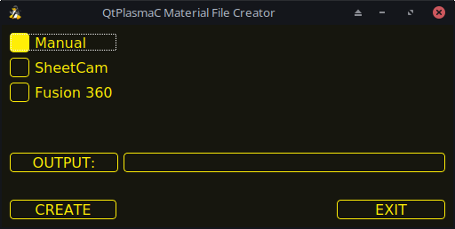
-
SheetCam - to convert a SheetCam tool file.
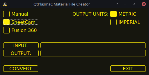
Wählen Sie nur für SheetCam, ob der Benutzer eine metrische oder imperiale Ausgabedatei benötigt.
-
Fusion 360 - to convert a Fusion 360 tool file.
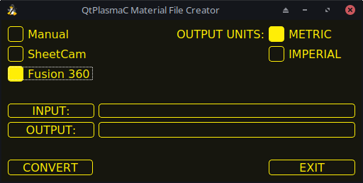
Um zu konvertieren:
-
Wählen Sie die zu konvertierende Eingabedatei, drücken Sie INPUT, um eine Dateiauswahl aufzurufen, oder geben Sie die Datei direkt in das Eingabefeld ein.
-
Select the Output File to write to, press OUTPUT to bring up a file selector or directly enter the file in the entry box. This would normally be ~/linuxcnc/configs/<machine_name>_material.cfg. If necessary, the user could select a different file and hand edit the <machine_name>_material.cfg file.
-
Klicken Sie auf CREATE/CONVERT und die neue Materialdatei wird erstellt.
Sowohl bei einer manuellen Erstellung als auch bei einer Fusion 360-Konvertierung wird ein Dialogfeld mit allen verfügbaren Parametern angezeigt, die eingegeben werden können. Jeder mit *** markierte Eintrag ist obligatorisch, alle anderen Einträge sind je nach den Konfigurationsanforderungen des Benutzers optional.
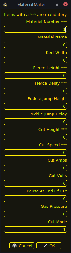
|
Anmerkung
|
If the user selects ~/linuxcnc/configs/<machine_name>_material.cfg and the file already exists, it will be overwritten. |
9.11. LASER
QtPlasmaC has the ability to use a laser to set the origin with or without rotation compensation. Rotation compensation can be used to align the work offset to a sheet of material with edge(s) that are not parallel to the machine’s X/Y axes. The LASER button will be enabled after the machine is homed.
Um diese Funktion zu nutzen, muss der Benutzer den Versatz des Lasers von der Brennermitte einstellen, indem er das unter Peripherie-Offsets beschriebene Verfahren befolgt.
To modify the offsets manually, the user could edit either or both the following options in the [LASER_OFFSET] section of the <machine_name>.prefs file:
X axis = n.n
Y axis = n.n
where n.n is distance from the center line of the torch to the laser’s cross hairs.
Zusätzlich kann der Laser über einen HAL-Pin mit folgendem Namen an einen beliebigen Ausgang angeschlossen werden, um den Laser ein- und auszuschalten:
qtplasmac.laser_onTo set the origin with zero rotation:
-
Klicken Sie auf die Schaltfläche LASER.
-
LASER button label will change to MARK EDGE and the HAL pin named qtplasmac.laser_on will be turned on.
-
Jog until the laser cross hairs are on top of the desired origin point.
-
Press MARK EDGE. The MARK EDGE button label will change to SET ORIGIN.
-
Press SET ORIGIN. The SET ORIGIN button label will change to MARK EDGE and the HAL pin named qtplasmac.laser_on will be turned off.
-
Der Brenner fährt nun in die Position X0 Y0.
-
Der Offset ist nun erfolgreich gesetzt.
To set the origin with rotation:
-
Klicken Sie auf die Schaltfläche LASER.
-
LASER button label will change to MARK EDGE and the HAL pin named qtplasmac.laser_on will be turned on.
-
Jog until the laser cross hairs are at the edge of the material a suitable distance away from the desired origin point.
-
Press MARK EDGE. The MARK EDGE button label will change to SET ORIGIN.
-
Jog until the laser cross hairs are at the origin point of the material.
-
Press SET ORIGIN. The SET ORIGIN button label will change to MARK EDGE and the HAL pin named qtplasmac.laser_on will be turned off.
-
Der Brenner fährt nun in die Position X0 Y0.
-
Der Offset ist nun erfolgreich eingestellt.
To turn the laser off and cancel an alignment:
-
Drücken Sie die Taste LASER und halten Sie sie länger als 750 mSek. gedrückt.
-
LASER button label will change to LASER and the HAL pin named qtplasmac.laser_on will be turned off.
-
Release the LASER button.
If an alignment laser has been set up then it is possible to use the laser during CUT RECOVERY for accurate positioning of the new start coordinates.
9.12. CAMERA
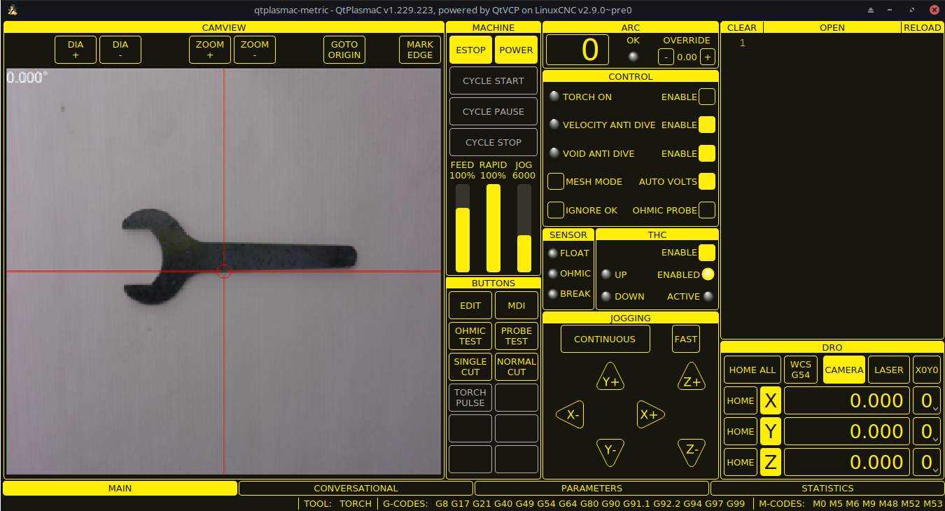
QtPlasmaC has the ability to use a USB camera to set the origin with or without rotation compensation. Rotation compensation can be used to align the work offset to a sheet of material with edge(s) that are not parallel to the machine’s X/Y axes. The CAMERA button will be enabled after the machine is homed.
Um diese Funktion zu nutzen, muss der Benutzer den Versatz der Kamera von der Brennermitte einstellen, indem er das unter Peripherie-Offsets beschriebene Verfahren befolgt.
To modify the offsets manually, the user could edit either or both the following axes options in the [CAMERA_OFFSET] section of the <machine_name>.prefs file:
X axis = n.n
Y axis = n.n
Camera port = 0
wobei n.n der Abstand von der Mittellinie des Brenners zum Fadenkreuz der Kamera ist.
To set the origin with zero rotation:
-
Bewegen Sie die Maus, bis sich das Fadenkreuz über dem gewünschten Ursprungspunkt befindet.
-
Drücken Sie MARK EDGE. Die Beschriftung der Schaltfläche MARK EDGE ändert sich in SET ORIGIN und die Schaltfläche GOTO ORIGIN wird deaktiviert.
-
Drücken Sie Ursprung festlegen. Die Beschriftung der Schaltfläche Herkunft festlegen ändert sich in KANTE MARKIEREN und die Schaltfläche Herkunft gehen wird aktiviert.
-
Der Brenner fährt nun in die Position X0 Y0.
-
Der Offset ist nun erfolgreich gesetzt.
To set the origin with rotation:
-
Bewegen Sie das Fadenkreuz, bis es sich am Rand des Materials in einem angemessenen Abstand zum gewünschten Ursprungspunkt befindet.
-
Drücken Sie MARK EDGE. Die Beschriftung der Schaltfläche MARK EDGE ändert sich in SET ORIGIN und die Schaltfläche GOTO ORIGIN wird deaktiviert.
-
Bewegen Sie die Maus, bis sich das Fadenkreuz am Ausgangspunkt des Materials befindet.
-
Drücken Sie Ursprung festlegen. Die Beschriftung der Schaltfläche Herkunft festlegen ändert sich in KANTE MARKIEREN und die Schaltfläche Herkunft gehen wird aktiviert.
-
Der Brenner fährt nun in die Position X0 Y0.
-
Der Offset ist nun erfolgreich eingestellt.
Im CAMVIEW-Bedienfeld kann die Maus das Fadenkreuz und die Zoomstufe wie folgt beeinflussen:
-
Mausrad scrollen - Durchmesser des Fadenkreuzes ändern.
-
Doppelklick mit der Mausradtaste - Stellt den Fadenkreuzdurchmesser auf den Standardwert zurück.
-
Linke Maustaste gedrückt + Scrollrad - Ändert die Zoomstufe der Kamera.
-
Klicken mit der linken Maustaste + Doppelklick mit der Radtaste - Stellt die Standard-Zoomstufe der Kamera wieder her.
9.13. Pfadtoleranz
Die Pfad-/Bahntoleranz wird mit einem G64-Befehl und einem nachfolgenden P-Wert eingestellt. Der P-Wert entspricht dem Betrag, um den die tatsächliche Schnittbahn, der die Maschine folgt, von der programmierten Schnittbahn abweichen darf.
Die Standard-LinuxCNC Bahntoleranz ist für die maximale Geschwindigkeit, die stark runden Ecken, wenn sie mit normalen Plasma-Schneidgeschwindigkeiten verwendet wird eingestellt.
Es wird empfohlen, die Pfad-Toleranz durch Einfügen des entsprechenden G64-Befehls und des P-Werts in den Kopf jeder G-Code-Datei festzulegen.
The provided G-code filter program will test for the existence of a G64 P__n__ command prior to the first motion command. If no G64 command is found it will insert a G64 P0.1 command which sets the path tolerance to 0.1 mm. For a imperial config the command will be G64 P0.004.
G64 P0.1
G64 P0.004
9.14. Angehaltene Bewegung
QtPlasmaC ermöglicht die Neupositionierung der X- und Y-Achse entlang des aktuellen Schnittpfades, während das G-Code-Programm pausiert.
Um diese Funktion nutzen zu können, muss die adaptive Vorschubsteuerung (M52) von LinuxCNC eingeschaltet sein (P1).
Um Paused Motion zu aktivieren, muss die Präambel des G-Codes die folgende Zeile enthalten:
M52 P1
Um Paused Motion an einem beliebigen Punkt zu deaktivieren, verwenden Sie den folgenden Befehl:
M52 P0
9.15. Pause am Ende von Cut
This feature can be used to allow the arc to "catch up" to the torch position to fully finish the cut. It is usually required for thicker materials and is especially useful when cutting stainless steel.
Using this feature will cause all motion to pause at the end of the cut while the torch is still on. After the dwell time (in seconds) set by the Pause At End parameter in the MATERIAL section of the PARAMETERS Tab has expired, QtPlasmaC will proceed with the M5 command to turn off and raise the torch.
9.16. Mehrere Werkzeuge
QtPlasmaC hat die Fähigkeit, die Verwendung von mehr als einer Art von Plasma-Werkzeug durch die Verwendung von LinuxCNC Spindeln als Plasma-Werkzeug bei der Ausführung eines G-Code-Programm zu ermöglichen.
Gültige Plasmageräte für den Einsatz sind:
| Name | Werkzeug # | Beschreibung |
|---|---|---|
Plasma-Brenner |
0 |
Wird für normales Plasmaschneiden verwendet. |
Scribe |
1 |
Wird für die Materialgravur verwendet. |
Plasma-Brenner |
2 |
Wird zum Tupfen (Erzeugen von Vertiefungen zur Unterstützung des Bohrens) verwendet. |
Eine LinuxCNC Spindelnummer (bezeichnet durch $n) ist erforderlich, um in den Start-Befehl und auch die Ende-Befehl, um in der Lage zu starten und stoppen Sie die richtige Plasma-Werkzeug sein. Beispiele:
-
M3 $0 S1will select and start the plasma cutting tool. -
M3 $1 S1will select and start the scribe. -
M3 $2 S1will select and start the plasma spotting tool. -
M5 $0will stop the plasma cutting tool. -
M5 $1will stop the scribe. -
M5 $2will stop the plasma spotting tool.
Es ist zulässig, M5 $-1 anstelle der obigen M5 $n-Codes zu verwenden, um alle Werkzeuge anzuhalten.
In order to use a scribe, it is necessary for the user to add the X and Y axis offsets to the LinuxCNC tool table. Tool 0 is assigned to the Plasma Torch and Tool 1 is assigned to the scribe. Tools are selected with a Tn M6 command, and then a G43 H0 command is required to apply the offsets for the selected tool. It is important to note that the LinuxCNC tool table and tool commands only come into play if the user is using a scribe in addition to a plasma torch. For more information, see scribe.
9.17. Geschwindigkeitsreduzierung
Es gibt einen HAL-Pin mit der Bezeichnung motion.analog-out-03, der im G-Code mit den Befehlen M67 (Synchronisiert mit Bewegung)/M68 (Sofort) geändert werden kann. Mit diesem Pin wird die Geschwindigkeit auf den im Befehl angegebenen Prozentsatz reduziert.
Es ist wichtig, den Unterschied zwischen Synchronisiert mit Bewegung und Sofort gründlich zu verstehen:
-
M67(Synchronized with Motion) - The actual change of the specified output (P2 (THC) for example) will happen at the beginning of the next motion command. If there is no subsequent motion command, the output changes will not occur. It is best practice to program a motion code (G0 or G1 for example) right after a M67. -
M68(Immediate) - These commands happen immediately as they are received by the motion controller. Since these are not synchronized with motion, they will break blending. This means if these codes are used in the middle of active motion codes, the motion will pause to activate these commands.
Beispiele:
-
M67 E3 Q0would set the velocity to 100% of CutFeedRate. -
M67 E3 Q40would set the velocity to 40% of CutFeedRate. -
M67 E3 Q60would set the velocity to 60% of CutFeedRate. -
M67 E3 Q100would set the velocity to 100% of CutFeedRate.
Der zulässige Mindestprozentsatz beträgt 10 %, darunter liegende Werte werden auf 10 % gesetzt.
Der maximal zulässige Prozentsatz beträgt 100%, darüber liegende Werte werden auf 100% gesetzt.
If the user intends to use this feature it would be prudent to add M68 E3 Q0 to both the preamble and postamble of the G-code program so the machine starts and ends in a known state.
|
Wichtig
|
G-CODE THC AND VELOCITY BASED THC ARE NOT ABLE TO BE USED IF CUTTER COMPENSATION IS IN EFFECT; AN ERROR MESSAGE WILL BE DISPLAYED. |
|
Warnung
|
If Cut Feed Rate in the MATERIAL section of the PARAMETERS Tab is set to Zero then QtPlasmaC will use motion.requested-velocity (as set by a standard Feedrate call in the G-code) for the THC calculations. This is not recommended as it is not a reliable way of implementing velocity based THC. |
|
Anmerkung
|
All references to CutFeedRate refer to the Cut Feed Rate value displayed in the MATERIAL section of the PARAMETERS Tab. |
9.18. THC (Brennerhöhensteuerung, engl. torch height controller)
The THC can be enabled or disabled from the THC frame of the MAIN Tab.
Die THC kann auch direkt über das G-Code-Programm aktiviert oder deaktiviert werden.
The THC does not become active until the velocity reaches 99.9% of the CutFeedRate and then the THC Delay time if any in the THC section of the PARAMETERS Tab has timed out. This is to allow the arc voltage to stabilize.
QtPlasmaC uses a control voltage which is dependent on the state of the AUTO VOLTS checkbox on the MAIN Tab:
-
Wenn Use Auto Volts aktiviert ist, wird die tatsächliche Abschaltspannung am Ende der THC Delay-Zeit abgetastet und als Zielspannung für die Einstellung der Brennerhöhe verwendet.
-
If Use Auto Volts is not checked then the voltage displayed as Cut Volts in the MATERIAL section of the PARAMETERS Tab is used as the target voltage to adjust the height of the torch.
THC may be disabled and enabled directly from G-code, provided the THC is not disabled in the THC Section of the MAIN Tab, by setting or resetting the motion.digital-out-02 pin with the M-Codes M62-M65:
-
M62 P2will disable THC (Synchronized with Motion) -
M63 P2will enable THC (Synchronized with Motion) -
M64 P2will disable THC (Immediately) -
M65 P2will enable THC (Immediately)
Es ist wichtig, den Unterschied zwischen Synchronisiert mit Bewegung und Sofort gründlich zu verstehen:
-
M62andM63(Synchronized with Motion) - The actual change of the specified output (P2 (THC) for example) will happen at the beginning of the next motion command. If there is no subsequent motion command, the output changes will not occur. It is best practice to program a motion code (G0 or G1 for example) right after a M62 or M63. -
M64andM65(Immediate) - These commands happen immediately as they are received by the motion controller. Since these are not synchronized with motion, they will break blending. This means if these codes are used in the middle of active motion codes, the motion will pause to activate these commands.
If the cut velocity falls below a percentage of CutFeedRate (as defined by the VAD Threshold % value in the THC frame of the CONFIGURATION section of the PARAMETERS Tab) the THC will be locked until the cut velocity returns to at least 99.9% of CutFeedRate. This will be made apparent by the VELOCITY ANTI DIVE indicator illuminating in the CONTROL Panel on the MAIN Tab.
Die geschwindigkeitsabhängige THC verhindert, dass die Brennerhöhe verändert wird, wenn die Geschwindigkeit für eine scharfe Ecke oder ein kleines Loch reduziert wird.
It is important to note that Velocity Reduction affects the Velocity Based THC in the following ways:
-
Wenn die Geschwindigkeitsreduzierung in der Mitte des Schnitts aufgerufen wird, dann wird die THC gesperrt.
-
The THC will remain locked until the velocity reduction is canceled by returning it to a value that is above the VAD Threshold, and the torch actually reaches 99.9% of the CutFeedRate.
9.19. Fräserkompensation
LinuxCNC (QtPlasmaC) has the ability to automatically adjust the cut path of the current program by the amount specified in Kerf Width of the selected material’s Cut Parameters. This is helpful if the G-code is programmed to the nominal cut path and the user will be running the program on different thickness materials to help ensure consistently sized parts.
To use cutter compensation the user will need to use G41.1, G42.1 and G40 with the kerf width HAL pin:
-
G41.1 D#<_hal[plasmac.kerf-width]>: offsets torch to the left of the programmed path -
G42.1 D#<_hal[plasmac.kerf-width]>: offsets torch to the right of the programmed path -
G40turns the cutter compensation off
|
Wichtig
|
IF CUTTER COMPENSATION IS IN EFFECT G-CODE THC, VELOCITY BASED THC AND OVER CUT ARE NOT ABLE TO BE USED; AN ERROR MESSAGE WILL BE DISPLAYED. |
9.20. Initial Height Sense (IHS) Skip
Initial Height Sense may be skipped in one of two different ways:
-
If the THC is disabled, or the THC is enabled but not active, then the IHS skip will occur if the start of the cut is less than Skip IHS distance from the last successful probe.
-
If the THC is enabled and active, then the IHS skip will occur if the start of the cut is less than Skip IHS distance from the end of the last cut.
A value of zero for Skip IHS will disable all IHS skipping.
Any errors encountered during a cut will disable IHS skipping for the next cut if Skip IHS is enabled.
9.21. Sondieren
Probing may be done with either ohmic sensing or a float switch. It is also possible to combine the two methods, in which case the float switch will provide a fallback to ohmic probing. An alternative to ohmic probing is Offset Probing
If the machine’s torch does not support ohmic probing, the user could have a separate probe next to the torch. In this case the user would extend the probe below the torch. The probe must NOT extend more than the minimum Cut Height below the torch and the Z axis offset distance needs to be entered as the Ohmic Offset in the PROBING frame of the CONFIGURATION section of the PARAMETERS Tab.
Probing setup is done in the PROBING frame of the CONFIGURATION section of the PARAMETERS Tab.
QtPlasmaC can probe at the full Z axis velocity so long as the machine has enough movement in the float switch to absorb any overrun. If the machine’s float switch travel is suitable, the user could set the Probe Height to near the Z axis MINIMUM_LIMIT and do all probing at full speed.
Some float switches can exhibit a large switching hysteresis which shows up in the probing sequence as an excessive time to complete the final probe up.
-
This time may be decreased by changing the speed of the final probe up.
-
This speed defaults to 0.001 mm (0.000039") per servo cycle.
-
It is possible to increase this speed by up to a factor of 10 by adding the following line to the custom.hal file:
setp plasmac.probe-final-speed n
where n is a value from 1-10. It is recommended to keep this value as low as possible.
Using this feature will change the final height slightly and will require thorough probe testing to confirm the final height.
This speed value affects ALL probing so if the user uses ohmic probing and the user changes this speed value then the user will need to probe test to set the require offset to compensate for this speed change as well as the float travel.
The reliability of this feature will only be as good as the repeatability of the float switch.
|
Anmerkung
|
Probe Height refers to the height above the Z axis MINIMUM_LIMIT. |
9.22. Offset Probing
Offset Probing is the use of a probe that is offset from the torch. This method is an alternative to Ohmic Probing and uses the plasmac.ohmic-enable output pin to operate a solenoid for extending and retracting the probe. The plasmac.ohmic-probe input pin is used to detect the material and the Ohmic Offset in the PROBING frame of the CONFIGURATION section of the PARAMETERS Tab is used to set the correct measured height.
The probe could be a mechanically deployed probe, a permanently mounted proximity sensor or even simply a stiff piece of wire extending about 0.5 mm (0.2") below the torch tip. If the probe is mechanically deployed then it needs to extend/retract rather quickly to avoid excessive probing times and would commonly be pneumatically operated.
To use this feature, the user must set the probe’s offset from the torch center by following the procedure described in Peripheral Offsets.
To modify the offsets manually, the user could edit either or both the following options in the [OFFSET_PROBING] section of the <machine_name>.prefs file:
X axis = n.n
Y axis = n.n
Delay = t.t
where n.n is the offset of the probe from the torch center in machine units for the X and Y axes and t.t is the time in seconds to allow for any mechanical deployment of the probe if required.
Each of these parameters is optional and also may appear in any order. If a parameter is not detected then the default is 0.0. There can be no space after the X or Z, lower case is permissible.
When this variable appears in the INI file with either X or Y not equal to zero then QtPlasmaC will do all Ohmic Probing as Offset Probing. When a probe sequence has begun, the plasmac.ohmic-enable pin will be set True causing the probe to extend. When the material is detected the plasmac.ohmic-enable pin will be reset to false causing the probe to retract.
The probe will begin moving to the offset position simultaneously with the Z axis moving down to the Probe Height, probing will not commence unless the deployment timer has completed. It is required that the Probe Height in the PROBING frame of the CONFIGURATION section of the PARAMETERS Tab is above the top of the material to ensure that the probe is fully offset to the correct X/Y position before the final vertical probe down movement.
|
Wichtig
|
PROBE HEIGHT NEEDS TO BE SET ABOVE THE TOP OF THE MATERIAL FOR OFFSET PROBING. |
9.23. Cut Types
QtPlasmaC allows two different cut modes:
-
NORMAL CUT - runs the loaded G-code program to pierce then cut.
-
PIERCE ONLY - only pierces the material at each cut start position, useful prior to a NORMAL CUT on thick materials
There are two ways of enabling this feature:
-
Utilize the default custom user button to toggle between the cut types.
-
Adding the following line to the G-code program before the first cut to enable Pierce Only mode for the current file:
#<pierce-only> = 1
If using a custom user button is utilized then QtPlasmaC will automatically reload the file when the cut type is toggled.
9.24. Hole Cutting - Intro
It is recommended that any holes to be cut have a diameter no less than one and a half times the thickness of the material to be cut.
It is also recommended that holes with a diameter of less than 32 mm (1.26") are cut at 60% of the feed rate used for profile cuts. This should also lock out THC due to velocity constraints.
QtPlasmaC can utilize G-code commands usually set by a CAM Post Processor (PP) to aid in hole cutting or if the user does not have a PP or the user’s PP does not support these methods then QtPlasmaC can automatically adapt the G-code to suit. This automatic mode is disabled by default.
Es gibt drei Methoden zur Verbesserung der Qualität von kleinen Löchern:
-
Velocity Reduction - Reducing the velocity to approximately 60% of the CutFeedRate.
-
Arc Dwell (Pause At End) - Keeping the torch on for a short time at the end of the hole while motion is stopped to allow the arc to catch up.
-
Over cut - Turning the torch off at the end of the hole then continue along the path.
|
Anmerkung
|
Wenn sowohl Arc Dwell als auch Over Cut gleichzeitig aktiv sind, hat Over Cut Vorrang. |
|
Wichtig
|
OVER CUT IS NOT ABLE TO BE USED IF CUTTER COMPENSATION IS IN EFFECT; AN ERROR MESSAGE WILL BE DISPLAYED. |
9.25. Löcher schneiden
G-Code-Befehle können entweder von einem CAM-Postprozessor (PP) oder durch Handcodierung erstellt werden.
If cutting a hole requires a reduced velocity then the user would use the following command to set the velocity: M67 E3 Qnn where nn is the percentage of the velocity desired. For example, M67 E3 Q60 would set the velocity to 60% of the current material’s CutFeedRate.
See the Velocity Based THC section.
G21 (metric)
G64 P0.005
M52 P1 (allow paused motion)
F#<_hal[plasmac.cut-feed-rate]> (feed rate from cut parameters)
G0 X10 Y10
M3 $0 S1 (start cut)
G1 X0
M67 E3 Q60 (reduce feed rate to 60%)
G3 I10 (the hole)
M67 E3 Q0 (restore feed rate to 100%)
M5 $0 (end cut)
G0 X0 Y0
M2 (end job)
This method can be invoked by setting the Pause At End parameter in the MATERIAL frame of the PARAMETERS Tab.
The torch can be turned off at the end of the hole by setting the motion.digital-out-03 pin with the M-Codes M62 (Synchronized with Motion)* or M64 (Immediate). After turning the torch off it is necessary to allow the torch to be turned on again before beginning the next cut by resetting the motion.digital-out-03 pin with the M-Codes M63 or M65, this will be done automatically by the QtPlasmaC G-code parser if it reaches an M5 command without seeing a M63 P3 or M65 P3.
After the torch is turned off the hole path will be followed for a default length of 4 mm (0.157"). This distance may be specified by adding #<oclength> = n to the G-code file.
-
M62 P3will turn the torch off (Synchronized with Motion) -
M63 P3will allow the torch to be turned on (Synchronized with Motion) -
M64 P3will turn the torch off (Immediately) -
M65 P3will allow the torch to be turned on (Immediately)
It is important to thoroughly understand the difference between Synchronized with motion and Immediate:
-
M62 and M63(Synchronized with Motion) - The actual change of the specified output (P2 (THC) for example) will happen at the beginning of the next motion command. If there is no subsequent motion command, the output changes will not occur. It is best practice to program a motion code (G0 or G1 for example) right after a M62 or M63. -
M64 and M65(Immediate) - These commands happen immediately as they are received by the motion controller. Since these are not synchronized with motion, they will break blending. This means if these codes are used in the middle of active motion codes, the motion will pause to activate these commands.
Sample code:
G21 (metric)
G64 P0.005
M52 P1 (allow paused motion)
F#<_hal[plasmac.cut-feed-rate]> (feed rate from cut parameters)
G0 X10 Y10
M3 $0 S1 (start cut)
G1 X0
M67 E3 Q60 (reduce feed rate to 60%)
G3 I10 (the hole)
M62 P3 (turn torch off)
G3 X0.8 Y6.081 I10 (continue motion for 4mm)
M63 P3 (allow torch to be turned on)
M67 E3 Q0 (restore feed rate to 100%)
M5 $0 (end cut)
G0 X0 Y0
M2 (end job)
9.26. Hole Cutting - Automatic
QtPlasmaC has the ability to automatically modify the G-code to reduce the velocity and/or apply Over cut which can be useful when cutting holes.
For valid hole sensing it is required that all values in the G2 or G3 G-code line are explicit, an error dialog will be displayed if any values are mathematically calculated.
QtPlasmaC Loch-Erkennung (engl. hole sensing) ist standardmäßig deaktiviert. Sie kann mit den folgenden G-Code-Parametern aktiviert/deaktiviert werden, um den gewünschten Lochabtastungsmodus auszuwählen:
-
#<holes> = 0- Causes QtPlasmaC to disable hole sensing if it was previously enabled. -
#<holes> = 1- Causes QtPlasmaC to reduce the speed of holes less than 32 mm (1.26") to 60% of CutFeedRate. -
#<holes> = 2- Causes QtPlasmaC to Over cut the hole in addition to the velocity changes in setting 1. -
#<holes> = 3- Causes QtPlasmaC to reduce the speed of holes less than 32 mm (1.26") and arcs less than 16 mm (0.63") to 60% of CutFeedRate. -
#<holes> = 4- Causes QtPlasmaC to Over cut the hole in addition to the velocity change in setting 3.
The default hole size for QtPlasmaC hole sensing is 32 mm (1.26"). It is possible to change this value with the following command in a G-code file:
-
#<h_diameter> =nn - To set a diameter (nn) in the same units system as the rest of the G-code file.
The default velocity for QtPlasmaC small holes is 60% of the current feed rate. It is possible to change this value with the following command in a G-code file:
-
#<h_velocity> =nn - to set the percentage (nn) of the current feed rate required.
If Hole Sensing modes 2 or 4 are active, QtPlasmaC will over cut the hole in addition to the velocity changes associated with modes 1 and 3.
The default over cut length for QtPlasmaC hole sensing is 4 mm (0.157"). It is possible to change this value with the following command in a G-code file:
-
#<oclength> =nn to specify an over cut length (nn) in the same units system as the rest of the G-code file.
This feature can be used in addition to setting the desired hole sensing mode via the appropriate G-code parameter by setting the Pause At End parameter in the MATERIAL frame of the PARAMETERS Tab.
G21 (metric)
G64 P0.005
M52 P1 (allow paused motion)
F#<_hal[plasmac.cut-feed-rate]> (feed rate from cut parameters)
#<holes> = 2 (over cut for holes)
#<oclength> = 6.5 (optional, 6.5mm over cut length)
G0 X10 Y10
M3 $0 S1 (start cut)
G1 X0
G3 I10 (the hole)
M5 $0 (end cut)
G0 X0 Y0
M2 (end job)
|
Anmerkung
|
It is OK to have multiple and mixed hole commands in a single G-code file. |
9.27. Single Cut
A single cut is a single unidirectional cutting move often used to cut a sheet into smaller pieces prior to running a G-code program.
The machine needs to be homed before commencing a single cut.
A single cut will commence from the machine’s current X/Y position.
This is the preferred method. The parameters for this method are entered in the following dialog box that is displayed after pressing a user button which has been coded to run single cut:
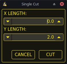
-
Jog to the required X/Y start position.
-
Set required appropriate material, or edit the Feed Rate for the default material in the PARAMETERS Tab.
-
Press the assigned single cut user button.
-
Enter the length of the cut along the X and/or Y axes.
-
Press the CUT button and the cut will commence.
If the machine is equipped with a pendant that can start and stop the spindle plus jog the X and Y axes, the user can manually perform a single cut.
-
Jog to the required X/Y start position.
-
Set the required feed rate with the Jog Speed slider.
-
Start the cut process by starting the spindle.
-
After probing the torch will fire.
-
When the Arc OK is received the machine can be jogged along the cut line using the jog buttons.
-
Wenn der Schnitt beendet ist, stoppen Sie die Spindel.
-
The torch will turn off and the Z axis will return to the starting position.
Manual single cut requires that either keyboard shortcuts are enabled in the GUI SETTINGS section of the SETTINGS Tab, or a custom user button is specified as a manual cut button.
If the user is using a custom user button then substitute F9 with User Button in the following description.
-
Jog to the required X/Y start position.
-
Start the procedure by pressing F9. The jog speed will be automatically set to the feed rate of the currently selected material. The jog label will blink to indicate that the jog speed is temporarily being overridden (jog speed manipulation will be disabled while a manual cut is active). CYCLE START will change to MANUAL CUT and blink.
-
After probing the torch will fire.
-
When the Arc OK is received the machine can be jogged along the cut line using the jog keys.
-
The Z height will remain locked at the cut height for the duration of the manual cut, regardless of the Torch Height Controller ENABLE status.
-
When the cut is complete press F9 or Esc or the CYCLE STOP button.
-
The torch will turn off and the Z axis will return to the starting position.
-
The jog speed will automatically be returned to the value it was prior to initiating the manual cut process, the label will stop blinking and the jog speed manipulation will be enabled. MANUAL CUT will stop blinking and revert to CYCLE START.
|
Anmerkung
|
If the torch flames out during cutting, the user must still press F9 or Esc or the CYCLE STOP button to end the cut. This clears the Z offsets and returns the torch to the starting position. |
9.28. Thick Materials
Cutting thick materials can be problematic in that the large amount of molten metal caused by piercing can shorten the life of consumables and also may cause a puddle high enough that the torch may hit the puddle while moving to cut height.
The are two functions built into QtPlasmaC to help alleviate these issues.
Pierce Only mode converts the loaded G-code program and then runs the program to pierce the material at the start position of each cut. Scribe and Spotting commands will be ignored and no pierce will take place in those locations.
This mode is useful for thick materials which may produce enough dross on the material surface from piercing to interfere with the torch while cutting. The entire sheet can pierced and then cleaned off prior to cutting.
It is possible to use near-end-of-life consumables for piercing and then they can be swapped out for good consumables to be used while cutting.
Pierce Only is one of two different cut types
Puddle Jump is the height that the torch will move to after piercing and prior to moving to Cut Height and is expressed as a percentage of Pierce Height. This allows the torch to clear any puddle of molten material that may be caused by piercing. The maximum allowable height is 200% of the Pierce Height
Setting for Puddle Jump are described in cut parameters
The recommended option is to use Pierce Only due to it being able to utilise near end of life consumables.
|
Wichtig
|
PUDDLE JUMP IS DISABLED DURING CUT RECOVERY |
9.29. Mesh Mode (Expanded Metal Cutting)
QtPlasmaC is capable of cutting of expand (mesh) metal provided the machine has a pilot arc torch and it is capable of Constant Pilot Arc (CPA) mode.
Mesh Mode disables the THC and also ignores a lost Arc OK signal during a cut. It can be selected by checking the Mesh Mode check button in the CONTROL section of the MAIN Tab.
If the machine has RS485 communications enabled with a Hypertherm PowerMax plasma cutter, selecting Mesh Mode will automatically override the Cut Mode for the currently selected material and set it to cut mode 2 (CPA). When Mesh Mode is disabled, the Cut Mode will be return to the default cut mode for the currently selected material.
It is also possible to start a Mesh Mode cut without receiving an Arc OK signal by checking the Ignore Arc OK check button in the CONTROL section of the MAIN Tab.
Both Mesh Mode and Ignore Arc OK can be enabled/disabled at any time during a job.
9.30. Ignore Arc OK
Ignore Arc OK mode disables the THC, will begin a cut without requiring an Arc OK signal, and will ignore a lost Arc OK signal during a cut.
This mode can be selected by:
-
Checking the Ignore Arc OK check button in the CONTROL section of the MAIN Tab.
-
Setting HAL pin motion.digital-out-01 to 1 via G-code.
-
M62 P1will enable Ignore Arc OK (Synchronized with Motion) -
M63 P1will disable Ignore Arc OK (Synchronized with Motion) -
M64 P1will enable Ignore Arc OK (Immediately) -
M65 P1will disable Ignore Arc OK (Immediately)
-
It is important to thoroughly understand the difference between Synchronized with motion and Immediate:
-
M62andM63(Synchronized with Motion) - The actual change of the specified output (P2 (THC) for example) will happen at the beginning of the next motion command. If there is no subsequent motion command, the output changes will not occur. It is best practice to program a motion code (G0 or G1 for example) right after a M62 or M63. -
M64andM65(Immediate) - These commands happen immediately as they are received by the motion controller. Since these are not synchronized with motion, they will break blending. This means if these codes are used in the middle of active motion codes, the motion will pause to activate these commands.
This mode may also be used in conjunction with Mesh Mode if the user doesn’t require an Arc OK signal to begin the cut.
Both Mesh Mode and Ignore Arc OK can be enabled/disabled at any time during a job.
9.31. Cut Recovery
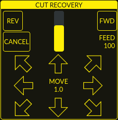
This feature will produce a CUT RECOVERY panel that will allow the torch to be moved away from the cut path during a paused motion event in order to position the torch over a scrap portion of the material being cut so that the cut restarts with a minimized arc-divot. The CUT RECOVERY panel will display automatically over top of the JOGGING panel when motion is paused.
It is preferable to make torch position adjustments from the point at which paused motion occurred, however if moving along the cut path is necessary prior to setting the new start point, the user may use the paused motion controls (REV, FWD, and a JOG-SPEED slider) at the top of the CUT RECOVERY panel. Once the user is satisfied with the positioning of the torch along the cut path, moving off the cut path is achieved by pressing the DIRECTION buttons. Each press of the DIRECTION button will move the torch a distance equivalent to the Kerf Width parameter of the currently selected material.
The moment the torch has been moved off the cut path, the paused motion controls (REV, FWD, and a JOG-SPEED slider) at the top of the CUT RECOVERY panel will become disabled.
Once the torch position is satisfactory, press CYCLE RESUME and the cut will resume from the new position and travel the shortest distance to the original paused motion location. The CUT RECOVERY panel will close and the JOGGING panel will display when the torch returns to the original paused motion location.
Pressing CANCEL MOVE will cause the torch to move back to where it was positioned before the direction keys were used to offset the torch. It will not reset any REV or FWD motion.
Pressing CYCLE STOP will cause the torch to move back to where it was positioned before the direction keys were used to offset the torch and the CUT RECOVERY panel overlay will return to the JOGGING panel. It will not reset any REV or FWD motion.
If an alignment laser has been set up then it is possible to use the laser during cut recovery for very accurate positioning of the new start coordinates. If either the X axis offset or Y axis offset for the laser would cause the machine to move out of bounds then an error message will be displayed.
To use a laser for cut recovery when paused during a cut:
-
Klicken Sie auf die Schaltfläche LASER.
-
LASER button will change to disabled, the HAL pin named qtplasmac.laser_on will be turned on and the X and Y axis will offset so that the laser cross hairs will indicate the starting coordinates of the cut when it is resumed.
-
Continue the cut recovery as described above.
If a laser offset is in effect when CANCEL MOVE is pressed then this offset will also be cleared.
|
Anmerkung
|
Cut recovery movements will be limited to a radius of 10 mm (0.4") from either the point the program was paused, or from the last point on the cut path if paused motion was used. |
|
Wichtig
|
PUDDLE JUMP IS DISABLED DURING CUT RECOVERY |
9.32. Run From Line
If the user has the Run From Line option enabled in the GUI SETTINGS section of the SETTINGS Tab then they will have the ability to start from any line in a G-code program via the following methods:
-
Clicking any line in the Preview Window
-
Clicking any line in the G-code Window
Note that the "Run From Line"-function will run from the beginning of the selected line.
It is important to note that G-code programs can be run from any selected line using this method, however a leadin may not be possible depending on the line selected. In this case, an error message will be displayed to let the user know the leadin calculation was not possible.
Once the user has selected the starting place, the CYCLE START button will blink "SELECTED nn" where nn is the corresponding line number selected. Clicking this button will bring up the following Run From Line dialog box:
It is not possible to use Run From Line from within a subroutine. If the user selects a line within a subroutine and clicks "SELECTED nn" then an error message will be displayed that includes the O-code name of the subroutine.
It is not possible to use Run From Line if previous G-code has set cutter compensation active. If the user selects a line while cutter compensation is active and clicks "SELECTED nn" then an error message will be displayed.
It is possible to select a new line while Run From Line is active.
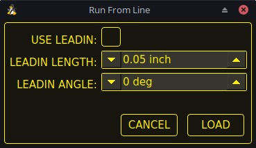
| Name | Beschreibung |
|---|---|
USE LEADIN |
This radio button will allow the user to start the selected line with a leadin. |
LEADIN LENGTH |
If USE LEADIN is selected, this will set the length of the lead in the machine units. |
LEADIN ANGLE |
If USE LEADIN is selected, this will set the angle of approach for the leadin. |
CANCEL |
This button will cancel the Run From Line dialog box and any selections. |
LOAD |
This button will load a temporary "rfl.ngc" program with any selected leadin parameters applied. |
After pressing LOAD, the blinking "SELECTED nn" button will change to RUN FROM LINE CYCLE START button. Click this button to start the program from the beginning of the selected line.
Run From Line selections may be canceled in the following ways:
-
Click the background of the preview window - this method will cancel a selection of either a cut line in the preview window, or a G-code line in the G-code window.
-
Click the text of the first line of the G-code program in the G-code display - this method will cancel a selection of either a cut line in the preview window, or a G-code line in the G-code window.
-
Klicken auf RELOAD in der Kopfzeile des G-Code-Fensters - diese Methode bricht den Prozess "Run From Line" ab, wenn im Dialogfeld "Run From Line" auf LOAD geklickt wurde und "rfl.ngc" als geladener Dateiname in der Kopfzeile des G-Code-Fensters angezeigt wird. Dadurch kehrt der Benutzer zur ursprünglich geladenen Datei zurück.
9.33. Scribe
Zusätzlich zum Plasmabrenner kann mit QtPlasmaC ein Ritzgerät betrieben werden.
Using a scribe requires the use of the LinuxCNC tool table. Tool 0 is assigned to the plasma torch and Tool 1 is assigned to the scribe. The scribe X and Y axes offsets from the plasma torch need to be entered into the LinuxCNC tool table. This is done by editing the tool table via the main GUI, or by editing the tool.tbl file in the <machine_name> configuration directory. This will be done after the scribe can move to the work piece to help determine the appropriate offset.
The plasma torch offsets for X and Y will always be zero. The tools are selected by the Tn M6 command followed by a G43 H0 command which is required to apply the offsets. The tool is then started with a M3 $n S1 command. For n, use 0 for torch cutting or 1 for scribing.
Um den Ritzvorgang zu stoppen, verwenden Sie den G-Code-Befehl M5 $1.
If the user has not yet assigned the HAL pins for the scribe in the configuration wizard then they may do so by using the appropriate configuration wizard or by manually editing the HAL file, see modifying QtPlasmaC.
There are two HAL output pins used to operate the scribe, the first pin is used to arm the scribe which moves the scribe to the surface of the material. After the Arm Delay has elapsed, the second pin is used to start the scribe. After the On Delay has elapsed, motion will begin.
Using QtPlasmaC after enabling the scribe requires the selection of either the torch or the scribe in each G-code file as a LinuxCNC tool.
The first step is to set the offsets for the scribe by following the procedure described in Peripheral Offsets.
The final step is to set the scribe delays required:
-
Arm Delay - allows time for the scribe to descend to the surface of the material.
-
On Delay - allows time for the scribe to start before motion begins.
Save the parameters in the Config tab.
After the above directions are completed, the scribe may be tested manually by issuing a M3 $1 S1 command in the MDI input. The user may find it helpful to use this method to scribe a small divot and then try to pulse the torch in the same location to align the offsets between the scribe and the torch.
To use the scribe from G-code:
...
M52 P1 (paused motion on)
F#<_hal[plasmac.cut-feed-rate]>
T1 M6 (select scribe)
G43 H0 (apply offsets for current tool)
M3 $1 S1 (start the scribe)
.
M5 $1 (stop the scribe)
.
T0 M6 (select torch)
G43 H0 (apply offsets for current tool)
G0 X0 Y0 (parking position)
M5 $-1 (end all)
It is a good idea to switch back to the torch at the end of the program before the final rapid parking move so the machine is always in the same state at idle.
The user can switch between the torch and the scribe any number of times during a program by using the appropriate G-codes.
Issuing M3 S1 (without $n) will cause the machine to behave as if an M3 $0 S1 had been issued and issuing M5 (without $n) will cause the machine to behave as if an M5 $0 had been issued. This will control the torch firing by default in order to provide backward compatibility for previous G-code files.
|
Warnung
|
If there is an existing manual tool change parameter set in the <machine_name>.hal file then QtPlasmaC will convert it to an automatic tool change. |
9.34. Spotting
To achieve spotting to mark the material prior to drilling etc., QtPlasmaC can pulse the torch for a short duration to mark the spot to drill.
Spotting can be configured by following these steps:
-
Set the arc voltage Threshold in the Spotting section of the PARAMETERS Tab. Setting the voltage threshold to zero will cause the delay timer to begin immediately upon starting the torch. Setting the voltage threshold above zero will cause the delay timer to begin when the arc voltage reaches the threshold voltage.
-
Set the Time On in the Spotting section of the PARAMETERS Tab. When the Time On timer has elapsed, the torch will turn off. Times are adjustable from 0 to 9999 milliseconds.
The torch is then turned on in G-code with the M3 $2 S1 command which selects the plasma torch as a spotting tool.
To turn the torch off, use the G-code command M5 $2.
For more information on multiple tools, see multiple tools.
LinuxCNC (QtPlasmaC) requires some motion between any M3 and M5 commands. For this reason, a minimal movement at a high speed is required to be programmed.
An example G-code is:
G21 (metric)
F99999 (high feed rate)
.
.
G0 X10 Y10
M3 $2 S1 (spotting on)
G91 (relative distance mode)
G1 X0.000001
G90 (absolute distance mode)
M5 $2 (spotting off)
.
.
G0 X0 Y0
G90
M2
|
Anmerkung
|
Die hohe Vorschubgeschwindigkeit von 99999 soll sicherstellen, dass die Bewegung bei der höchsten Vorschubgeschwindigkeit der Maschine erfolgt. |
|
Wichtig
|
EINIGE PLASMA-CUTTER SIND FÜR DIESE FUNKTION NICHT GEEIGNET. ES WIRD EMPFOHLEN, DASS DER BENUTZER EINIGE TESTFLECKEN DURCHFÜHRT, UM SICHERZUSTELLEN, DASS DER PLASMA-CUTTER DIESE FUNKTION NUTZEN KANN. |
9.35. Benutzerdefinierte Layouts für virtuelle Tastaturen
Virtuelle Tastaturunterstützung ist nur für die "integrierte" Bildschirmtastatur verfügbar. Wenn es sich noch nicht auf dem System befindet, kann es installiert werden, indem Sie Folgendes in ein Terminal eingeben:
sudo apt install onboardDie folgenden beiden benutzerdefinierten Layouts werden für die Softkey-Unterstützung verwendet:
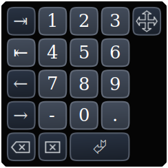
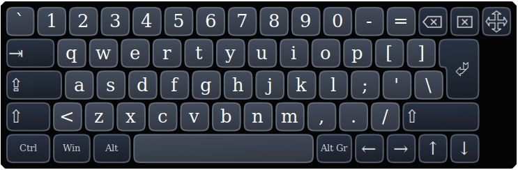
If the virtual keyboard has been repositioned and on the next opening of a virtual keyboard it is not visible then clicking twice on the onboard icon in the system tray will reposition the virtual keyboard so the move handle is visible.
9.36. Tastatürkürzel
Nachfolgend finden Sie eine Liste aller verfügbaren Tastaturkürzel in QtPlasmaC.
|
Anmerkung
|
Alle Tastaturkürzel sind standardmäßig deaktiviert. |
In order to utilize them, KB Shortcuts must be enabled in the GUI SETTINGS section of the SETTINGS Tab.
| Keyboard Shortcut | Action |
|---|---|
Esc |
Aborts current automated motion (example: a running program, a probe test, etc.) as well as an active torch pulse (behaves the same as clicking CYCLE STOP). |
F1 |
Toggles the GUI E-STOP button (if the GUI E-STOP button is enabled). |
F2 |
Toggles the GUI power button. |
F9 |
Toggles the "Cutting" command, used to begin or end a manual cut. |
F12 |
Show stylesheet editor. |
ALT+RETURN |
Places QtPlasmaC into Manual Data Input (MDI) mode. |
`, 1-9, 0 |
Changes jog speed to 0%, 10%-90%, 100% of the value present in the DEFAULT_LINEAR_VELOCITY variable in the [DISPLAY] section of the <machine_name>.ini file. |
SHIFT+`, 1-9, 0 |
Changes rapid speed to 0%, 10%-90%, 100%. |
CTRL+1-9, 0 |
Changes feed rate to 10%-90%, 100%. |
CTRL+HOME |
Homes all axes if they are not yet homed and have a homing sequence set in the <machine_name>.ini file. If they are already homed, they will no longer be homed. |
CTRL+R |
Cycle Start if the program is not already running. Cycle Resume if the program is paused. |
END |
Touches off X and Y to 0. |
DEL |
Allows the user to use a laser to set an origin with or without rotation. See the LASER section for detailed instructions. |
SPACE BAR |
Pauses motion. |
CTRL+SPACE BAR |
Clears notifications. |
O |
Opens a new program. |
L |
Loads the previously opened program if no program is loaded. Reloads the current program if there is a program loaded. |
→ |
Jogs the X axis positive. |
← |
Jogs the X axis negative. |
↑ |
Jogs the Y axis positive. |
↓ |
Jogs the Y axis negative. |
PAGE UP |
Jogs the Z axis positive. |
PAGE DOWN |
Joggt die Z-Achse negativ. |
[ |
Joggt die A-Achse positiv. |
] |
Joggt die A-Achse negativ. |
. |
Joggt die B-Achse positiv. |
, |
Joggt die B-Achse negativ. |
SHIFT (+ Jog-Taste) |
Die "Umschalttaste" (auch "Hochtaste", engl. shift key) wird zusammen mit einer beliebigen Jog-Taste verwendet, um ein schnelles Joggen auszulösen. |
+ (+Jog Taste) |
Die Plus-Taste kann mit jeder Jog-Taste verwendet werden, um einen schnellen Jog aufzurufen (verhält sich wie SHIFT). |
- (+Jog Taste) |
Die Minustaste kann mit einer beliebigen Tipptaste verwendet werden, um einen langsamen Tippbetrieb (10% der angezeigten Tippgeschwindigkeit) aufzurufen. Wenn der langsame Tippbetrieb bereits aktiv ist, wird die Achse mit der angezeigten Jog-Geschwindigkeit verfahren. |
9.37. MDI
Zusätzlich zu den typischen G- und M-Codes, die von LinuxCNC im MDI-Modus erlaubt sind, kann die MDI in QtPlasmaC verwendet werden, um auf mehrere andere praktische Funktionen zuzugreifen. Der folgende Link umreißt die Funktionen und ihre Verwendung: [sub:qtvcp:widgets:mdiline][MDILine Widget]
|
Anmerkung
|
M3, M4 und M5 sind in der QtPlasmaC MDI nicht erlaubt. |
In addition, pressing RETURN (or ENTER) with no entry in the MDI will close the MDI window.
10. Conversational Shape Library
The Conversational Shape Library consists of several basic shapes and functions to assist the user with generating quick G-code at the machine to cut simple shapes quickly. This feature is found on the CONVERSATIONAL Tab.
|
Anmerkung
|
The Conversational Library is not meant to be a CAD/CAM replacement as there are limitations to what can be achieved. |
Bei leeren Einträgen in den Form-Eingabefeldern wird die aktuelle Einstellung zum Zeitpunkt der Erstellung des G-Codes verwendet. Wenn z.B. X Start leer gelassen wurde, wird die aktuelle Position der X-Achse verwendet.
Alle An- und Ableitungen (engl. leadins und leadouts) sind Bögen, mit Ausnahme von Kreisen und Sternen:
Circles:
-
Wenn der Kreis extern ist, dann ist jede Hin- oder Rückführung (leadin or leadout) ein Bogen.
-
Wenn der Kreis innenliegend ist und ein kleines Loch hat, dann ist jeder leadin senkrecht und es gibt keinen Auslauf.
-
Wenn der Kreis intern und kein kleines Loch ist, dann ist jeder Leadin und Leadout ein Bogen. Wenn der Leadin eine Länge von mehr als der Hälfte des Radius hat, wird der Leadin senkrecht zurückgesetzt und es gibt keinen Leadout. Wenn der Leadout eine Länge von mehr als der Hälfte des Radius hat, gibt es keinen Leadout.
Stars:
-
Der Leadin befindet sich im gleichen Winkel wie der erste Schnitt und der Leadout im gleichen Winkel wie der letzte Schnitt.
|
Anmerkung
|
Ein kleines Loch ist ein Kreis, der kleiner ist als der auf der Seite KONVERSATIONSEINSTELLUNGEN (engl. conversational settings) angegebene KLEINE LOCHDURCHMESSER. |
|
Anmerkung
|
The holes in a BOLT CIRCLE shape will also abide by the above rules. |
The cut order will occur in the same order as the shape was built.
Wenn Sie während der Bearbeitung der Parameter Return auf der Tastatur drücken, wird automatisch die Vorschau der Form angezeigt, wenn genügend Parameter eingegeben wurden, um die Form zu erstellen. Ein Klick auf eines der verfügbaren Kontrollkästchen bewirkt dasselbe.
Die allgemeinen Funktionen sind wie folgt:
| Name | Beschreibung |
|---|---|
Material-Dropdown |
Allows the user to select the desired material for cutting. |
NEW |
Removes the current G-code file and load a blank G-code file. |
SAVE |
Opens a dialog box allowing the current shape to be saved as a G-code file. |
SETTINGS |
Allows the changing of the global settings. |
SEND |
Loads the current shape into LinuxCNC (QtPlasmaC). If the last edit was not added then it will be discarded. |
PREVIEW |
Displays a preview of the current shape provided the required information is present. |
CONTINUE |
This button is used for lines and arcs only. Allows another segment to be added to the current segment/segments. |
ADD |
Stores the current shape into the current job. |
UNDO |
Reverts to the previously stored state. |
NEU LADEN |
Reloads the original G-code file or a blank file if none was loaded. |
If there is a G-code file loaded in LinuxCNC (QtPlasmaC) when the CONVERSATIONAL Tab is selected, that code will be imported into the conversational as the first shape of the job. If this code is not required then it can be removed by pressing the NEW button.
If there is an added shape that is unsaved or unsent then it is not possible to switch tabs in the GUI. To re-enable switching tabs it is necessary to either SAVE the shape, SEND the shape, or press NEW to remove the shape.
Wenn NEU gedrückt wird, um eine hinzugefügte Form zu entfernen, die nicht gespeichert oder gesendet wurde, wird ein Warndialog angezeigt.
|
Anmerkung
|
Alle Entfernungen sind in Maschineneinheiten relativ zum aktuellen Benutzerkoordinatensystem und alle Winkel sind in Grad angegeben. |
10.1. Konversationseinstellungen
Global settings for the shape library can be set by pressing the SETTINGS button in the CONVERSATIONAL Tab. This will display all of the available settings parameters that are used for G-code program creation. These include:
-
Preamble
-
Postamble
-
Origin (Center or Bottom Left)
-
Leadin length
-
Leadout length
-
Small hole diameter
-
Small hole speed
-
Preview Window Grid Size
Jeder Innenkreis mit einem Durchmesser kleiner als Kleiner Lochdurchmesser wird als kleine Bohrung klassifiziert und hat einen geraden Einstich mit einer Länge, die kleiner ist als entweder der Radius der Bohrung oder die angegebene Einstichlänge. Außerdem wird die Vorschubgeschwindigkeit auf Kleine Bohrungsgeschwindigkeit eingestellt.
Präambel und Postambel können als eine durch Leerzeichen getrennte Folge von G-Codes und M-Codes eingegeben werden. Wenn der Benutzer möchte, dass der generierte G-Code jeden Code in einer eigenen Zeile enthält, kann er dies durch Trennen der Codes mit \n erreichen.
Dadurch werden alle Codes in dieselbe Zeile gesetzt:
G21 G40 G49 G64p0.1 G80 G90 G92.1 G94 G97
Dadurch wird jeder Code in eine eigene Zeile gesetzt:
G21\nG40\nG49\nG64p0.1\nG80\nG90\nG92.1\nG94\nG97
Wenn Sie die Taste RELOAD drücken, werden alle geänderten, aber nicht gespeicherten Einstellungen verworfen.
Durch Drücken der Taste SAVE werden alle Einstellungen wie angezeigt gespeichert.
Wenn Sie die Taste EXIT drücken, wird das Einstellungsfeld geschlossen und Sie kehren zur vorherigen Form zurück.
10.2. Konversationslinien und Bögen

Linien und Bögen haben eine zusätzliche Option, indem sie aneinandergereiht werden können, um eine komplexe Form zu schaffen.
Es stehen zwei Linienarten und drei Bogenarten zur Verfügung:
-
Line given a start point and an end point.
-
Line given a start point, length, and angle.
-
Arc given a start point, way point, and end point.
-
Arc given a start point, end point, and radius.
-
Arc given a start point, length, angle, and radius.
Nutzung von Linien und Bögen:
-
Wählen Sie das Symbol Linien und Bögen aus.
-
Wählen Sie den Typ der zu erstellenden Linie oder des Bogens.
-
Choose the material from the MATERIAL drop down. If no material is chosen, the default material (00000) will be used.
-
Geben Sie die gewünschten Parameter ein.
-
Drücken Sie PREVIEW, um die Form zu sehen.
-
Wenn Sie mit der Form zufrieden sind, drücken Sie CONTINUE.
-
Ändern Sie bei Bedarf den Linien- oder Bogentyp und fahren Sie mit diesem Verfahren fort, bis die Form vollständig ist.
-
Drücken Sie SEND, um die G-Code-Datei zum Schneiden an LinuxCNC (QtPlasmaC) zu senden.
Wenn der Benutzer eine geschlossene Form erstellen möchte, muss er alle erforderlichen Anfänge als das erste Segment der Form erstellen. Wenn ein Auslauf erforderlich ist, muss dieser das letzte Segment der Form sein.
|
Anmerkung
|
In diesem Stadium gibt es keine automatische Option für die Erstellung eines Leadin/Leadout, wenn die Form geschlossen ist. |
10.3. Conversational Single Shape
Die folgenden Formen sind für die Erstellung verfügbar:
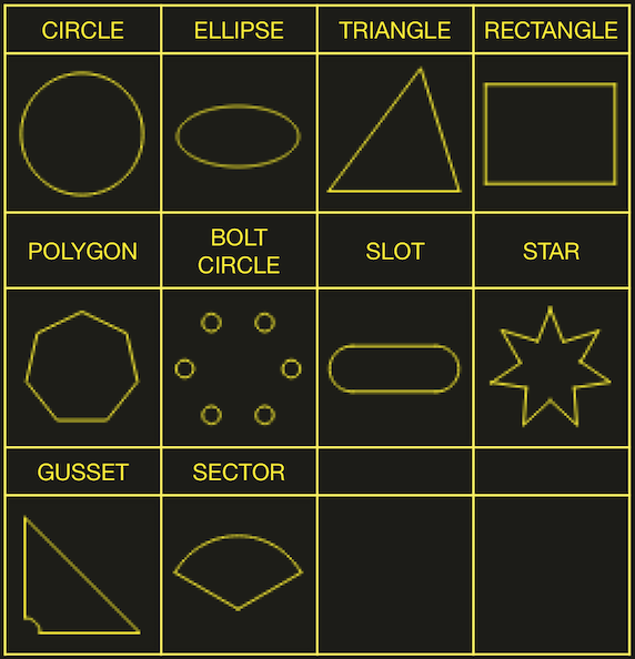
So erstellen Sie eine Form:
-
Select the corresponding icon for the shape to create. The available parameters will be displayed.
-
Choose the material from the MATERIAL drop down. If no material is chosen, the default material (00000) will be used.
-
Geben Sie die entsprechenden Werte ein und drücken Sie PREVIEW, um die Form anzuzeigen.
-
Wenn die Form nicht korrekt ist, ändern Sie die Werte und drücken Sie VORSCHAU (engl. preview), damit die neue Form angezeigt wird. Wiederholen Sie den Vorgang, bis Sie mit der Form zufrieden sind.
-
Drücken Sie ADD, um die Form zur G-Code-Datei hinzuzufügen.
-
Drücken Sie SEND, um die G-Code-Datei zum Schneiden an LinuxCNC (QtPlasmaC) zu senden.
For CIRCLE, the OVER CUT button will become valid when a CUT TYPE of INTERNAL is selected and the value entered in the DIAMETER field is less than the Small Hole Diameter parameter in the Conversational SETTINGS section.
For BOLT CIRCLE the OVER CUT button will become valid if the value entered in the HOLE DIA field is less than the SMALL HOLES DIAMETER parameter in the Conversational SETTINGS section.
For the following shapes, KERF OFFSET will become active once a LEAD IN is specified:
-
TRIANGLE
-
RECTANGLE
-
POLYGON
-
SLOT
-
STAR
-
GUSSET
10.4. Conversational Group Of Shapes
Multiple shapes can be added together to create a complex group.
The cut order of the group is determined by the order in which the individual shapes are added to the group.
Once a shape is added to the group it cannot be edited or removed.
Groups cannot have shapes removed, only added to.
To create a group of shapes:
-
Create the first shape as in Single Shape.
-
Drücken Sie ADD und die Form wird der Gruppe hinzugefügt.
-
Wenn der Benutzer eine weitere Version der gleichen Form hinzufügen möchte, bearbeiten Sie die erforderlichen Parameter und drücken Sie ADD, wenn Sie mit der Form zufrieden sind.
-
Wenn der Benutzer eine andere Form hinzufügen möchte, wählen Sie diese Form aus und erstellen Sie sie wie bei einer Einzelnen Form.
-
Wiederholen Sie diesen Vorgang, bis alle erforderlichen Formen zur Vervollständigung der Gruppe hinzugefügt wurden.
-
Drücken Sie SEND, um die G-Code-Datei zum Schneiden an LinuxCNC (QtPlasmaC) zu senden.
10.5. Conversational Block
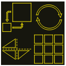
The Conversational Block feature allows block operations to be performed on the current shape or group of shapes displayed in the CONVERSATIONAL Tab. This can include a G-code file not created using the Conversational Shape Library that has been previously loaded from the MAIN Tab.
A previously saved Block G-code file may also be loaded from the MAIN Tab and then have any of its operations edited using the Conversational Block feature.
Blockoperationen:
-
Rotate
-
Skala
-
Array
-
Mirror (engl. für Spiegel)
-
Flip (engl. für umdrehen)
Um einen Block zu anzulegen:
-
Erstellen Sie eine Form oder eine Gruppe, oder verwenden Sie eine zuvor geladene G-Code-Datei.
-
Klicken Sie auf das Blocksymbol, um die Block-Tabelle zu öffnen.
-
Geben Sie die entsprechenden Werte auf der Registerkarte Block ein und drücken Sie VORSCHAU, um die resultierenden Änderungen anzuzeigen.
-
Wenn das Ergebnis nicht korrekt ist, ändern Sie die Werte und drücken Sie VORSCHAU und das neue Ergebnis wird angezeigt. Wiederholen Sie den Vorgang, bis Sie mit dem Ergebnis zufrieden sind.
-
Drücken Sie ADD (engl. für hinzufügen), um den Vorgang abzuschließen.
-
Drücken Sie SEND, um die G-Code-Datei an LinuxCNC (QtPlasmaC) zum Schneiden zu senden, oder SAVE, um die G-Code-Datei zu speichern.
- COLUMNS & ROWS
-
specifies the number of duplicates of the original shape arranged in columns and rows as well as the offset distance from the original shape.
- ORIGIN
-
offset the result from the origin coordinates.
- ANGLE
-
rotate the result.
- SCALE
-
scale the result.
- ROTATION
-
rotate the shape within the result.
- MIRROR
-
mirror the shape about its X coordinates within the result.
- FLIP
-
flip the shape about its Y coordinates within the result.
Wenn das Ergebnis ein Array von Formen ist, dann ist die Schnittreihenfolge des Ergebnisses von der linken Spalte zur rechten Spalte, beginnend mit der untersten Zeile und endend mit der obersten Zeile.
10.6. Conversational Saving A Job
The current job displayed in the Preview Panel may be saved at any time by using the bottom SAVE button. If the G-code has been sent to LinuxCNC (QtPlasmaC) and the user has left the CONVERSATIONAL Tab, the user may still save the G-code file from the GUI. Alternatively, the user could click the CONVERSATIONAL Tab which will reload the job, at which time they can press the SAVE button.
11. Fehlermeldungen
11.1. Fehlerprotokollierung
All errors are logged into the machine log which is able to be viewed in the STATISTICS Tab. The log file is saved into the configuration directory when QtPlasmaC is shutdown. The five last logfiles are kept, after which the oldest logfile is deleted each time a new log file is created. These saved log files may be viewed with any text editor.
11.2. Error Message Display
By default, QtPlasmaC will display error messages via a Operator Error popup window. In addition, QtPlasmaC will alert the user that an error has been sent to the machine log by displaying the message "ERROR SENT TO MACHINE LOG" in the lower left portion of the status bar.
The user may opt to disable the Operator Error popup window, and view the error messages by going to the STATISTICS Tab by changing the following option to False in the [SCREEN_OPTIONS] of the <machine_name>.prefs file in the <machine_name> directory:
desktop_notify|
Anmerkung
|
<machine_name>.prefs must be edited with QtPlasmaC closed or any changes will be overwritten on exit. |
Additionally, it is possible for ERROR SENT TO MACHINE LOG to flash to get the user’s attention by adding or editing the following option in the [GUI_OPTIONS] section of the <machine_name>.prefs file:
Flash error = True
11.3. Critical Errors
There are a number of error messages printed by QtPlasmaC to inform the user of faults as they occur. The messages can be split into two groups, Critical and Warning.
Critical Errors will cause the running program to pause, and the operator will need to clear the cause of the error before proceeding.
If the error was received during cutting then forward or reverse motion is allowed while the machine is paused to enable the user to reposition the machine prior to resuming the cut.
When the error is cleared the program may be resumed.
These errors indicate the corresponding sensor was activated during cutting:
-
breakaway switch activated, program is paused
-
float switch activated, program is paused
-
ohmic probe activated, program is paused
Diese Fehler deuten darauf hin, dass der entsprechende Sensor aktiviert wurde, bevor die Sondierung begann:
-
ohmic probe detected before probing program is paused
-
float switch detected before probing program is paused
-
breakaway switch detected before probing program is paused
Das Lichtbogen-OK-Signal ging während der Schneidbewegung verloren, bevor der Befehl M5 erreicht wurde:
-
valid arc lost program is paused
Die Z-Achse erreichte die untere Grenze, bevor das Werkstück erkannt wurde:
-
bottom limit reached while probing down program is paused
The work piece is too high for any safe rapid removes:
-
material too high for safe traverse, program is paused
One of these values in MATERIAL section of the PARAMETERS Tab is invalid (For example: if they are set to zero):
-
invalid pierce height or invalid cut height or invalid cut volts, program is paused
No arc has been detected after attempting to start the number of times indicated by Max Starts in the ARC frame of the CONFIGURATION section of the PARAMETERS Tab:
-
no arc detected after <n>d start attempts program is paused
-
no arc detected after <n>d start attempts manual cut is stopped
THC hat dazu geführt, dass die Untergrenze beim Schneiden erreicht wurde:
-
bottom limit reached while THC moving down program is paused
THC hat dazu geführt, dass die Obergrenze beim Schneiden erreicht wird:
-
top limit reached while THC moving up program is paused
These errors indicate move to pierce height would exceed the Z Axis MAX_LIMIT for the corresponding probe method:
-
pierce height would exceed Z axis maximum limit condition found while moving to probe height during float switch probing
-
pierce height would exceed Z axis maximum limit condition found while moving to probe height during ohmic probing
These errors indicate the move to pierce height would exceed the Z axis maximum safe height for the corresponding probe method:
-
pierce height would exceed Z axis maximum safe height condition found while float switch probing
-
pierce height would exceed Z axis maximum safe height condition found while ohmic probing
11.4. Warning Messages
Warning messages will not pause a running program and are informational only.
These messages indicate the corresponding sensor was activated before a probe test commenced:
-
ohmic probe detected before probing probe test aborted
-
float switch detected before probing probe test aborted
-
breakaway switch detected before probing probe test aborted
This indicates that the corresponding sensor was activated during a consumable change:
-
breakaway, float, or ohmic activated during consumable change, motion is paused
WARNING: MOTION WILL RESUME IMMEDIATELY UPON RESOLVING THIS CONDITION!
|
Warnung
|
CONSUMABLE CHANGE MOTION WILL RESUME IMMEDIATELY UPON RESOLVING THE CORRESPONDING SENSOR ACTIVATION. |
This indicates that the corresponding sensor was activated during probe testing:
-
breakaway switch detected during probe test
This indicates that probe contact was lost before probing up to find the zero point:
-
probe trip error while probing
This indicates that the bottom limit was reached during a probe test:
-
bottom limit reached while probe testing
This indicates that the move to pierce height would exceed the Z Axis MAX_LIMIT during the corresponding probe method:
-
pierce height would exceed Z axis maximum limit condition found while moving to probe height during float switch probe testing
-
pierce height would exceed Z axis maximum limit condition found while moving to probe height during ohmic probe testing
Dies zeigt an, dass die sichere Höhe reduziert wurde, weil THC die Z-Achse während des Schneidens anhebt:
-
safe traverse height has been reduced
This indicates that the value for the Arc Voltage was invalid (NAN or INF) when QtPlasmaC launched.
-
invalid arc-voltage-in
12. Updating QtPlasmaC
12.1. Standard Update
QtPlasmaC update notices are posted at https://forum.linuxcnc.org/plasmac/37233-plasmac-updates .
Users are strongly encouraged to create a Username and subscribe to the above thread to receive update notices.
For a standard ISO installation, LinuxCNC will only be updated when a new minor release has been released. QtPlasmaC will then automatically update its configuration the first time it is run after a LinuxCNC update.
LinuxCNC is normally updated by entering the following commands into a terminal window (one at a time):
sudo apt update
sudo apt dist-upgrade
12.2. Continuous Update
Enhancements and bug fixes will not be available on a standard installation until a new minor release of LinuxCNC has been released. If the user wishes to update whenever a new QtPlasmaC version has been pushed, they could use the LinuxCNC Buildbot repository rather than the standard LinuxCNC repository by following the instructions at http://buildbot.linuxcnc.org/ .
13. Modify An Existing QtPlasmaC Configuration
There are two ways to modify an existing QtPlasmaC configuration:
-
Running the appropriate configuration wizard and loading the .conf file saved by the wizard.
-
Manually edit the INI and/or the HAL file of the configuration.
|
Wichtig
|
Any manual modification to the <machine_name>.ini and <machine_name>.hal files will not be registered in PnCconf or StepConf. |
|
Anmerkung
|
If unsure of the HAL pin’s full name, the user may start LinuxCNC and run HalShow for a full listing of all HAL pins. |
14. Customizing QtPlasmaC GUI
Styling of the QtPlasmaC GUI is done with Qt stylesheets and some customization may be achieved by the use of a custom stylesheet. This allows the user to change some GUI items such as color, border, size, etc. It cannot change the layout of the GUI.
Information on Qt stylesheets is available here.
There are two methods available to apply custom styles:
-
Add A Custom Style: use this for minor style changes.
-
Create A New Style use this for a complete style change.
14.1. Add A Custom Style
Adding style changes to the default stylesheet is achieved by creating a file in the <machine_name> configuration directory. This file MUST be named qtplasmac_custom.qss. Any required style changes are then added to this file.
For example the user may want the arc voltage display in red, a green Torch On LED of a larger size and a larger Torch Enable button. This would be done with the following code in qtplasmac_custom.qss:
#arc_voltage {
    color: #ff0000 }

#led_torch_on {
    qproperty-diameter: 30;
    qproperty-color: green }

#torch_enable::indicator {
    width: 30;
    height: 30}
14.2. Create A New Style
Custom stylesheets are enabled by setting the following option in the [GUI_OPTIONS] section of the <machine_name>.prefs file. This option must be set to the filename of the stylesheet as shown below.
Custom style = the_cool_style.qss
The filename may be any valid filename. The standard extension name is .qss but this is not mandatory.
There are some constraints on the custom stylesheet for QtPlasmaC, e.g., the jog buttons, cut-recovery buttons, and the conversational shape buttons are image files and are not able to be custom styled.
The custom style file requires a header in the following format:
/*****************************
Custom Stylesheet Header

color1 = #000000
#QtPlasmaC default = #ffee06

color2 = #e0e0e0
#QtPlasmaC default = #16160e

color3 = #c0c0c0
#QtPlasmaC default = #ffee06

color4 = #e0e0e0
#QtPlasmaC default = #26261e

color5 = #808080
#QtPlasmaC default = #b0b0b0

*****************************/
The colors may be expressed in any valid stylesheet format.
The above colors are used for the following widgets. So any custom styling will need to take these into account. The colors shown below are the defaults used in QtPlasmaC along with the color name from the SETTINGS Tab.
| Farbe | Parameter | Affects |
|---|---|---|
color1 (#ffee06) |
Foreground |
foreground of jog buttons |
color2 (#16160e) |
Background |
background of latching user buttons |
color3 (#ffee06) |
Highlight |
background of active latching user buttons |
color4 (#36362e) |
Alt Background |
Hintergrund der aktiven Zeile der G-Code-Anzeige |
14.3. Rückkehr zum Standardstil
Der Benutzer kann jederzeit zum Standard-Styling zurückkehren, indem er die folgenden Schritte ausführt:
-
Schließen von QtPlasmaC, falls geöffnet.
-
Löschen Sie qtplasmac.qss aus dem Maschinen-Konfigurationsverzeichnis.
-
Löschen von qtplasmac_custom.qss aus dem Maschinen-Konfigurationsverzeichnis (falls vorhanden).
-
Open <machine_name>.prefs file.
-
Delete the [COLOR_OPTIONS] section.
-
Delete the Custom style option from the [GUI_OPTIONS] section.
-
Save the file.
Beim nächsten Laden von QtPlasmaC wird das gesamte benutzerdefinierte Styling entfernt und das Standard-Styling wird wiederhergestellt.
Below is an example of the section and options to be deleted from <machine_name>.prefs:
[COLOR_OPTIONS]
Foreground = #ffee06
Highlight = #ffee06
LED = #ffee06
Background = #16160e
Background Alt = #36362e
Frames = #ffee06
Estop = #ff0000
Disabled = #b0b0b0
Preview = #000000
14.4. Custom Python Code
It is possible to add custom Python code to change some existing functions or to add new ones. Custom code can be added in two different ways: a user command file or a user periodic file.
A user command file is specified in the DISPLAY section of the <machine_name>.ini file and contains Python code that is processed only once during startup.
USER_COMMAND_FILE = my_custom_code.py
A user periodic file must be named user_periodic.py and must be loaded in the machines config directory. This file is processed every cycle (usually 100 ms) and is used for functions that require regular updating.
14.5. Custom G-code Filter
All incoming G-code is parsed by a G-code filter to ensure it is suitable for QtPlasmaC. It is possible to extend this filter with custom python code executed from a file in the configuration directory to aid in converting different flavours of G-code to a format suitable for QtPlasmaC.
The name of this file is custom_filter.py and it will be automatically used if it exists.
There are three preset methods available for use:
| Name | Funktion |
|---|---|
custom_pre_process |
This does basic processing of each line before any processing is done in the filter. |
custom_pre_parse |
This parses any G-code from a line before any parsing done in the filter. |
custom_post_parse |
This parses any G-code from a line after any parsing done in the filter. |
These methods are applied by the following procedure:
-
Define the method with an argument for the incoming data.
-
Add any required code to manipulate the data.
-
Return the resultant data.
-
Attach the new method.
For example to remove any code beginning with G71 and change M2 to M5 $0 and M2:
def custom_pre_parse(data):
    if data[:3] == 'G71':
        return(None)
    if data == 'M2':
        return(f'M5 $0\n\n{data}')
    return(data)
self.custom_pre_parse = custom_pre_parse
In addition to these it is also possible to override any existing method in the filter the same way. This requires defining the same number of arguments as the existing method, noting that self in the original does not constitute an argument.
def new_method_name(data):
    if data[:3] == 'G71':
        return(None)
    return(data)
self.old_method_name = new_method_name
|
Anmerkung
|
The existing filter code may be observed in the file /bin/qtplasmac_gcode. The file sim/qtplasmac/custom_filter.py has example skeleton code for custom filtering. |
15. QtPlasmaC Fortgeschrittene Themen
15.1. Benutzerdefinierte Buttons
The QtPlasmaC GUI offers user buttons that can be customized by adding commands in the USER BUTTON ENTRIES section of the SETTINGS Tab in the <machine_name>.prefs file.
Die Anzahl der Benutzertasten variiert je nach Anzeigetyp und Auflösung wie folgt:
-
16:9 und 4:3 - Minimum 8, Maximum 20
-
9:16 - Minimum 15, Maximum 20
Der Benutzer muss QtPlasmaC bei der gewünschten Bildschirmgröße ausführen, um festzustellen, wie viele Benutzertasten zur Verfügung stehen.
All <machine_name>.prefs file settings for the buttons are found in the [BUTTONS] section.
Der Text, der auf einem Button erscheint, wird auf folgende Weise festgelegt:
n Name = HAL Show
Where n is the button number and HAL Show is the text.
For text on multiple lines, split the text with a \ (backslash):
n Name = HAL\Show
Wenn ein Ampersand als Text angezeigt werden soll, sind zwei aufeinander folgende Ampersands erforderlich:
n Name = PIERCE&&CUT
Die Schaltflächen können folgende Funktionen ausführen:
To run an external command, the command is preceded by a % character.
n Code = %halshow
To run an external Python script, the script name is preceded by a % character and it also requires a .py extension. It is valid to use the ~ character as a shortcut for the users home directory.
n Code = %halshow
To run G-code, just enter the code to be run.
n Code = G0 X100
To run an existing subroutine.
n Code = o<the_subroutine> call
<machine_name>.ini file variables can be entered by using the standard LinuxCNC G-code format. If expressions are included then they need to be surrounded by brackets.
n Code = G0 X#<_ini[joint_0]home> Y1
n Code = G53 G0 Z[#<_ini[axis_z]max_limit> - 1.001]
<machine_name>.prefs file variables and also <machine_name>.ini variables can be entered by enclosing each option in {} . You must put a space after each } if there are any following characters. If expressions are included then they need to be surrounded by brackets.
BUTTON_n_CODE = G0 X{LASER_OFFSET X axis} Y{LASER_OFFSET Y axis}
BUTTON_n_CODE = G0 X{JOINT_0 HOME} Y1
BUTTON_n_CODE = G53 G0 Z[{AXIS_Z MAX_LIMIT} - 1.001]
Multiple codes can be run by separating the codes with a "\" (backslash) character. The exception is the special commands which are required to be a single command per button.
n Code = G0 X0 Y0 \ G1 X5 \ G1 Y5
External commands and G-code may be mixed on the same button.
n Code = %halshow \ g0x.5y.5 \ %halmeter
The following code will allow the user to use a button to invert the current state of a HAL bit pin:
n Code = toggle-halpin the-hal-pin-name
This code is required to be used as a single command and may only control one HAL bit pin per button.
The button colors will follow the state of the HAL pin.
After setting the code, upon clicking, the button will invert colors and the HAL pin will invert pin state. The button will stay "latched" until the button is clicked again, which will return the button to the original colors and the HAL pin to the original pin state.
There are three External HAL Pins that are available to toggle as an output, the pin names are qtplasmac.ext_out_0, qtplasmac.ext_out_1, and qtplasmac.ext_out_2. HAL connections to these HAL pins need to be specified in a postgui HAL file as the HAL pins are not available until the QtPlasmac GUI has loaded.
For toggle-halpin buttons, it is possible for the user to mark the associated HAL pin as being required to be turned "ON" before starting a cut cycle by adding "runcritical" after the HAL pin in the button code. If TORCH ENABLE is checked and CYCLE START is pressed while the "runcritical" button is not "ON" then the user will receive a dialog warning them as such and asking to CONTINUE or CANCEL.
n Code = toggle-halpin the-hal-pin-name runcritical
The following code will allow the user to use a button to invert the current state of the alignment laser HAL bit pin:
n Code = toggle-laser
This code is also able to be used as a multiple command with G-code or external commands but may control only the alignment laser HAL bit pin.
The button colors will follow the state of the alignment laser HAL pin.
After setting the code, upon clicking, the button will invert colors and the alignment laser HAL pin will invert pin state. The button will stay "latched" until the button is clicked again, which will return the button to the original colors and the alignment laser HAL pin to the original pin state.
The following code would allow the user to use a button to invert the current state of the alignment laser HAL bit pin and then move the X and Y axes to the offset for the alignment laser as specified in the <machine_name>.prefs file:
n Code = G0 X{LASER_OFFSET X axis} Y{LASER_OFFSET Y axis} \ toggle-laser
The position of the "toggle-laser" command is not important as it is always the first command actioned regardless of position.
The following code will allow the user to use a button to pulse a HAL bit pin for a duration of 0.5 seconds:
n Code = pulse-halpin the-hal-pin-name 0.5
This code is required to be used as a single command and may only control one HAL bit pin per button.
The pulse duration is specified in seconds, if the pulse duration is not specified then it will default to one second.
The button colors will follow the state of the HAL pin.
After setting the code, upon clicking the button, the button will invert colors, the HAL pin will invert pin state, and the time remaining will be displayed on the button. The button color and the pin state will stay inverted until the pulse duration timer has completed, which will return the button to the original colors, the HAL pin to the original pin state, and the original button name.
An active pulse can be canceled by clicking the button again.
There are three External HAL Pins that are available to pulse as an output, the pin names are qtplasmac.ext_out_0, qtplasmac.ext_out_1, and qtplasmac.ext_out_2. HAL connections to these HAL pins need to be specified in a postgui HAL file as the HAL pins are not available until the QtPlasmac GUI has loaded.
QtPlasmaC will begin a probe and when the material is detected, the Z axis will rise to the Pierce Height currently displayed in the MATERIAL section of the PARAMETERS Tab. If the user has "View Material" selected in the GUI SETTINGS section of the SETTINGS Tab, this value will be displayed in the top left corner of the PREVIEW Window next to PH:.
QtPlasmaC will then wait in this state for the time specified (rounded to no decimal places) before returning the Z axis to the starting position. An example of a 6 second delay is below. If there is no time specified then the probe time will default to 10 seconds.
n Code = probe-test 6
|
Anmerkung
|
Enabling a user button as a Probe Test button will add an external HAL pin that may be connected from a pendant etc. HAL connections to this HAL pin needs to be specified in a postgui HAL file as the HAL pin is not available until the QtPlasmac GUI has loaded. |
QtPlasmaC will enable the Ohmic Probe Enable output signal and if the Ohmic Probe input is sensed, the LED indicator in the SENSOR Panel will light. The main purpose of this is to allow a quick test for a shorted torch tip.
n Code = ohmic-test
|
Anmerkung
|
Enabling a user button as an Ohmic Test button will add an external HAL pin that may be connected from a pendant etc. HAL connections to this HAL pin needs to be specified in a postgui HAL file as the HAL pin is not available until the QtPlasmac GUI has loaded. |
This button if selected will toggle between the two cut types, Pierce and Cut (default cutting mode) or Pierce Only.
n Code = cut-type
Pressing this button moves the torch to the specified coordinates when the machine is paused to allow the user easy access to change the torch consumables.
Valid entries are Xnnn Ynnn Fnnn. At least one of the X or Y coordinates are required, Feed Rate (F) is optional.
The X and Y coordinates are in absolute machine coordinates. If X or Y are missing then the current coordinate for that axis will be used.
Feed Rate (F) is optional, if it is missing or invalid then the feed rate of the current material will be used.
There are three methods to return to the previous coordinates:
-
Press the Change Consumables button again - the torch will return to the original coordinates and the machine will wait in this position for the user to resume the program.
-
Press CYCLE RESUME - the torch will return to the original coordinates and the program will resume.
-
Press CYCLE STOP - the torch will return to the original coordinates and the program will abort.
n Code = change-consumables X10 Y10 F1000
|
Anmerkung
|
Enabling a user button as a Change Consumables button will add an external HAL pin that may be connected from a pendant etc. HAL connections to this HAL pin needs to be specified in a postgui HAL file as the HAL pin is not available until the QtPlasmac GUI has loaded. |
Loading a G-code program from the directory specified by the PROGRAM_PREFIX variable in the <machine_name>.ini file (usually ~/linuxcnc/nc_files) is possible by using the following format:
n Code = load G-code.ngc
If the user’s G-code file is located in a sub-directory of the PROGRAM_PREFIX directory, it would be accessed by adding the sub-directory name to the beginning of the G-code file name. Example for a sub-directory named plasma:
n Code = load plasma/G-code.ngc
Note that the first "/" is not necessary as it will be added automatically.
Pulse the torch on for a predetermined time. The time must be specified in seconds using up to one decimal place. The maximum allowable time is 3 seconds, anything specified above that value will be limited to 3 seconds. An example of a 0.5 second pulse is below. It there is no time specified then it will default to 1 second. Pulse times with more than one decimal place will be rounded to one decimal place.
Pressing the button again during the countdown will cause the torch to be turned off, as will pressing Esc if keyboard shortcuts are enabled in the SETTINGS Tab.
If the button is released before the countdown is complete then the torch will turn off at countdown completion, holding the button on until after the countdown has completed will cause the torch to remain on until the button has been released.
n Code = torch-pulse 0.5
|
Anmerkung
|
Enabling a user button as a Torch Pulse button will add an external HAL pin that may be connected from a pendant etc. HAL connections to this HAL pin needs to be specified in a postgui HAL file as the HAL pin is not available until the QtPlasmac GUI has loaded. |
Run a single unidirectional cut. This utilises the automatic Single Cut feature.
n Code = single-cut
Framing is the ability to move the torch around the perimeter of a rectangle that encompasses the bounds of the current job.
The laser enable HAL pin (qtplasmac.laser_on) will be turned on during the framing moves and any X/Y offsets for the laser pointer in the <machine_name>.prefs file will also be applied to the X/Y motion. After the framing motion is completed, the torch will move to the X0 Y0 position to clear any applied laser offsets and qtplasmac.laser_on will be turned off.
Upon starting a Framing cycle, it is important to note that by default the Z axis will be moved to a height of [AXIS_Z]MAX_LIMIT - 5 mm (0.2") before X/Y motion begins.
The velocity for the XY movements of the Framing motion can be specified so that Framing motion always occurs at a set velocity. This can be achieved by adding the feed rate (F) as the as the last portion of the button code. If the feed rate is omitted from the button code, framing motion velocity will default to the feed rate for the currently selected material.
The following GUI buttons and Keyboard Shortcuts (if enabled in the SETTINGS Tab) are valid during Framing motion:
-
Pressing CYCLE STOP or the ESC keyboard shortcut - Stops Framing motion.
-
Pressing CYCLE PAUSE or the SPACE BAR keyboard shortcut- Pauses Framing motion.
-
Pressing CYCLE RESUME or the CTRL+r keyboard shortcut- Resumes paused Framing motion.
-
Changing the FEED SLIDER or any of the CTRL+0-9 keyboard shortcuts - Slows the feed rate.
|
Anmerkung
|
IF THE FEED RATE IS CHANGED FOR THE FRAMING MOTION, IT WILL BE NECESSARY TO RETURN THE FEED SLIDER TO 100% BEFORE PRESSING CYCLE START AND CUTTING THE LOADED JOB. |
n Code = framing
It is possible for the user to omit the initial default Z movement and run the framing sequence at the current Z height by adding "usecurrentzheight" after "framing".
n Code = framing usecurrentzheight
To specify a feed rate:
n Code = framing F100
oder:
n Code = framing usecurrentzheight F100
Enabling a user button as a framing button will add an external HAL pin that may be connected from a pendant etc. HAL connections to this HAL pin needs to be specified in a postgui HAL file as the HAL pin is not available until the QtPlasmac GUI has loaded.
Manual Cut functions identically to the F9 button to begin or end a manual cut.
n Code = manual-cut
This allows the showing/hiding of an offset viewing screen that displays all machine offsets. All relative offsets can be edited and the G54 ~ G59.3 work system coordinates are able to be given custom names.
n Code = offsets-view
This allows the loading of the last modified file in a directory. The directory name is optional and if omitted will default to the last directory a file was loaded from.
n Code = latest-file /home/me/linuxcnc/nc_files/qtplasmac-test
This allows the showing/hiding of the online HTML user manual specific to the version of LinuxCNC currently running. Note that internet access is required for this functionality.
n Code = user-manual
15.2. Peripheral Offsets (Laser, Camera, Scribe, Offset Probe)
Use the following sequence to set the offsets for a laser, camera, scribe, or offset probe:
-
Place a piece of scrap material under the torch.
-
Die Maschine muss referenziert und im Leerlauf sein, bevor Sie fortfahren.
-
Open the SETTINGS tab.
-
Click the SET OFFSETS button which opens the Set Peripheral Offsets dialog.
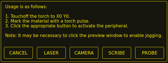
-
Click the X0Y0 button to set the torch position to zero.
-
Make a mark on the material by one of:
-
Jog the torch down to pierce height then pulse the torch on to make a dimple in the material.
-
Place marking dye on the torch shield then jog the torch down to mark the material.
-
-
Click the appropriate button to activate the peripheral.
-
The Get Peripheral Offsets dialog will now be showing.
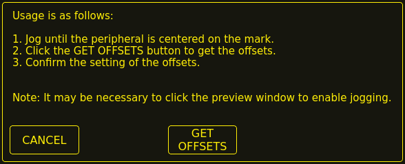
-
Raise the Z axis so the torch and peripheral are clear of the material.
-
Jog the X/Y axes so that the peripheral is centered in the mark from the torch.
-
Click the GET OFFSETS button to get the offsets and a confirmation dialog will open.
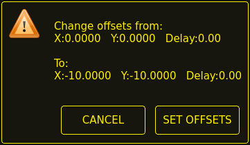
-
Click SET OFFSETS and the offsets will now be saved.
Canceling may be done at any stage by pressing the CANCEL button which will close the dialog and no changes will be saved.
If CAMERA was selected at item 7 above and more than one camera exists then a camera selection dialog will show. The appropriate camera needs to be selected before the Get Peripheral Offsets dialog will appear.
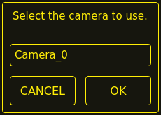
If PROBE was selected at item 7 above then a delay dialog will show prior to the confirmation dialog at item 11. This is for the delay required for the probe to deploy to its working position.
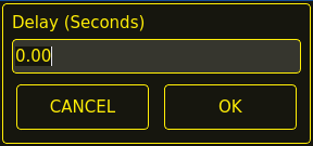
|
Anmerkung
|
It may be necessary to click the preview window to enable jogging. By following the above procedure the offsets are available for use immediately and no restart of LinuxCNC is required. |
15.3. Keep Z Motion
By default, QtPlasmaC will remove all Z motion from a loaded G-code file and add an initial Z movement to bring the torch near the top of travel at the beginning of the file. If the user wishes to use their table with a marker, a drag knife, diamond scribe, etc. mounted in the torch holder, QtPlasmaC has the ability to retain the Z movements when executing a program by adding the following command in a G-code file:
#<keep-z-motion> = 1
Omitting this command, or setting this value to anything but 1 will cause QtPlasmaC to revert to the default behavior of stripping all Z motion from a loaded G-code file and making an initial Z movement to bring the torch near the top of travel at the beginning of the file.
15.4. Externe HAL-Pins
QtPlasmaC erstellt einige HAL-Pins, die für den Anschluss eines externen Tasters oder einer Fernbedienung usw. verwendet werden können.
HAL connections to these HAL pins need to be specified in a postgui HAL file as the HAL pins are not available until the QtPlasmac GUI has loaded.
Die folgenden HAL-Bit-Pins werden immer erzeugt. Der HAL-Pin hat das gleiche Verhalten wie der zugehörige QtPlasmaC GUI-Button.
| User Button Function | HAL Pin | GUI Function |
|---|---|---|
Maschinenleistung umschalten |
|
POWER (engl. für Leistung oder Strom) |
Run the loaded G-code program |
|
ZYKLUSSTART |
Pause/Resume the loaded G-code program |
|
ZYKLUSPAUSE |
Abort the loaded G-code program |
|
ZYKLUS STOP (engl. cycle stop) |
Touchoff X & Y axes to zero |
|
X0Y0 |
Use a laser to set an origin with or without rotation |
|
LASER |
Toggle qtplasmac.laser_on pin |
|
k.A. |
Run/Pause/Resume the loaded G-code program |
|
CYCLE START, CYCLE PAUSE, CYCLE RESUME in sequence |
Torch height override plus |
|
OVERRIDE |
Torch height override minus |
|
OVERRIDE - |
Brennerhöhen-Override zurückgesetzt |
|
OVERRIDE RESET TO 0.00 |
Übersteuerungsskala für die Brennerhöhe |
|
k.A. |
Umschalten der Jogginggeschwindigkeit zwischen schnell und langsam |
|
SCHNELL/LANGSAM JOGGEN |
THC ein-/ausschalten |
|
THC AKTIVIEREN |
Brenner ein-/ausschalten |
|
BRENNER AKTIVIEREN |
Umschalten Ecke Sperre aktivieren |
|
VELOCITY ANTI DIVE ENABLE |
Voidlock-Freigabe umschalten |
|
VOID ANTI DIVE ENABLE |
Wechsel auto-Volts ein/aus |
|
AUTO VOLTS |
Ohmsche Sonde ein-/ausschalten |
|
OHMISCH AKTIVIEREN |
Toggle mesh mode |
|
MESH MODE |
Toggle arc ignore OK |
|
IGNORE OK |
Vorwärts entlang des programmierten Pfades |
|
CUT RECOVERY FWD |
Rückwärts entlang des programmierten Pfads |
|
CUT RECOVERY REV |
Cancel any Cut Recovery movement |
|
CUT RECOVERY CANCEL MOVE |
Move up |
|
CUT RECOVERY arrow up |
Move down |
|
CUT RECOVERY arrow down |
Move right |
|
CUT RECOVERY arrow right |
Move left |
|
CUT RECOVERY arrow left |
Move up-right |
|
CUT RECOVERY arrow up-right |
Move up-left |
|
CUT RECOVERY arrow up-left |
Move down-right |
|
CUT RECOVERY arrow down-right |
Move down-left |
|
CUT RECOVERY arrow down-left |
Die folgenden HAL-Stifte ermöglichen die Verwendung eines MPG zur Steuerung der Höhenüberwindung und werden immer erstellt.
| Funktion | HAL Pin |
|---|---|
MPG-Höhenkontrolle einschalten |
|
MPG Höhe ändern |
|
The following HAL bit pins are only created if the function is specified in a custom user button. The HAL pin has the identical behaviour of the related custom user button.
| User Button Function | HAL Pin |
|---|---|
Sonden-Test |
|
Brenner-Puls |
|
Ohmscher Test |
|
Verbrauchsmaterialien wechseln |
|
Framing |
|
The following HAL bit output pins are always created and can be used by either the Toggle HAL Pin or Pulse HAL Pin custom user buttons to change the state of an output.
| HAL Pin |
|---|
qtplasmac.ext_out_0 |
qtplasmac.ext_out_1 |
qtplasmac.ext_out_2 |
15.5. Programm-Buttons ausblenden
If the user has external buttons and/or a pendant that emulates any of the program buttons, CYCLE START, CYCLE PAUSE, or CYCLE STOP then it is possible to hide any or all of these GUI program buttons by adding the following options to the [GUI_OPTIONS] section of the <machine_name>.prefs file:
Hide run = True
Hide pause = True
Hide abort = True
For the 16:9 or 4:3 GUIs, the hiding of each of these GUI buttons will expose two more custom user buttons in the GUI.
15.6. Tuning-Modus 0 Arc OK
Modus 0 Arc OK basiert auf der Lichtbogenspannung, um das Arc OK-Signal zu setzen. Dies wird durch Abtasten der Lichtbogenspannung in jedem Servogewindezyklus erreicht. Damit das Lichtbogen-OK-Signal gesetzt wird, muss eine bestimmte Anzahl aufeinander folgender Abtastungen vorliegen, die alle innerhalb eines bestimmten Schwellenwerts liegen. Diese Spannungen müssen auch innerhalb eines bestimmten Bereichs liegen.
There are two settings in the PARAMETERS Tab for setting the range, these are:
-
OK High Volts which is the upper value of the voltage range. The default is 250 V.
-
OK Low Volts which is the lower value of the voltage range. The default is 60 V.
Both of these values may be changed by direct entry or by the use of the increment/decrement buttons.
There are also two HAL pins that have been provided to allow the user to tune the set point. These HAL pins are:
-
plasmac.arc-ok-countswhich is the number of consecutive readings within the threshold that are required to set the Arc OK signal. The default is 10. -
plasmac.arc-ok-thresholdwhich is the maximum voltage deviation that is allowed for a valid voltage to set the Arc OK signal. The default is 10.
The following example would set the number of valid consecutive readings required to 6:
setp plasmac.arc-ok-counts 6
These settings if used should be in the custom.hal file of the configuration.
15.7. Lost Arc Delay
Some plasma power sources/machine configurations may lose the Arc OK signal either momentarily during a cut, or permanently near the end of a cut causing QtPlasmaC to pause the program and report a "valid arc lost" error.
There is a HAL pin named plasmac.arc-lost-delay that may be used to set a delay (in seconds) that will prevent a paused program/error if the lost Arc OK signal is regained, or the M5 command is reached before the set delay period expires.
It is important to note that the THC will be disabled and locked at the cutting height at the time the Arc OK signal was lost.
The following code would set a delay of 0.1 seconds:
setp plasmac.arc-lost-delay 0.1
It is recommended that the user set this pin in the custom.hal file.
This setting should only be used if the user experiences the above symptoms. It should also be noted that the user could use the appropriate Ignore Arc OK G-code commands to achieve a similar result.
15.8. Zero Window
Small fluctuations in the arc voltage displayed while the machine is at idle are possible depending on many different variables (electrical noise, incorrect THCAD tuning, etc.).
After all contributing factors have been mitigated, if a small fluctuation still exists it is possible to eliminate it by widening the voltage window for which QtPlasmaC will display 0 V.
The pin for adjusting this value is named plasmac.zero-window and the default value is set to 0.1. To change this value, add the pin and the required value to the custom.hal file.
The following example would set the voltage window to be displayed as 0 V from -5 V to +5 V:
setp plasmac.zero-window 5
15.9. Tuning Void Sensing
In addition to the Void Slope setting in the PARAMETERS Tab there are two HAL pins to aid in the fine tuning of void anti-dive. These HAL pins are:
-
plasmac.void-on-cycles which is the number of times the slope rate needs to be exceeded to activate void anti-dive. The default is 2.
-
plasmac.void-off-cycles which is the number of cycles without the slope rate being exceeded to deactivate void anti-dive. The default is 10.
The following example would set the number of on cycles required to 3:
setp plasmac.void-on-cycles 3
The objective is to have as low a value of Void Slope as possible without any false triggering then adjust on and off cycles to ensure clean activation and deactivation of void anti-dive. In most cases it should not be necessary to change on and off cycles from the default value.
These settings if used should be in the custom.hal file of the configuration.
15.10. Max Offset
Max Offset is the distance (in millimeters) away from the Z MAX_LIMIT that QtPlasmaC will allow the Z axis to travel while under machine control.
The pin for adjusting this value is named plasmac.max-offset and the default value (in millimeters) is set to 5. To change this value, add the pin and the required value to the custom.hal file. It is not recommended to use values less than 5 mm as offset overrun may cause unforeseen issues.
The following example would set the distance from Z MAX_LIMIT to 10 mm:
setp plasmac.max-offset 10
15.11. Enable Tabs During Automated Motion
By default, all tabs except the MAIN Tab are disabled during automated motion. It is possible for every tab but the CONVERSATIONAL Tab to be enabled during automated motion by setting the following HAL pin True:
setp qtplasmac.tabs_always_enabled 1
|
Warnung
|
It is the responsibility of the operator to ensure that the machine is equipped with a suitable, working hardware E-stop. If using only a touchscreen to navigate the QtPlasmaC GUI, there is no way to stop automated machine motion on any tab but the MAIN tab. |
15.12. Override Jog Inhibit Via Z+ Jog
It is possible to override the jog inhibit by using the GUI or keyboard to jog in the Z+ direction rather than checking the Override Jog box on the SETTINGS Tab.
This is done by changing the following option to True in the [GUI_OPTIONS] of the <machine_name>.prefs file in the <machine_name> folder:
Override jog inhibit via Z+
15.13. QtPlasmaC State Outputs
The plasmac HAL component has a HAL pin named plasmac.state-out which can be used to interface with user-coded components to provide the current state of the component.
| Zustand | Name | Beschreibung |
|---|---|---|
0 |
|
idle and waiting for a start command |
1 |
|
move down to probe height |
2 |
|
probe down until material sensed |
3 |
|
probe up until material not sensed, this sets the zero height |
4 |
|
not used at present |
5 |
|
move up to pierce height |
6 |
|
turn the torch on |
7 |
|
wait until arc ok detected |
8 |
|
wait for pierce delay time |
9 |
|
xy motion begins, move to puddle jump height |
10 |
|
move to cut height |
11 |
|
cutting in either mode 0 or mode 1 |
12 |
|
cutting in mode 2 |
13 |
|
pause motion at end of cut |
14 |
|
move to safe height |
15 |
|
move to maximum height |
16 |
|
end the current cut |
17 |
|
end the current job |
18 |
|
a torch pulse is active |
19 |
|
cut recovery motion is active while paused |
20 |
|
an ohmic test is active |
21 |
|
a probe test is active |
22 |
|
a scribing job is active |
23 |
|
move to consumable change coordinates |
24 |
|
return from consumable change coordinates |
25 |
|
cut recovery is active |
26 |
|
cut recovery is deactivated |
The DEBUG state is for testing purposes only and will not normally be encountered.
15.14. QtPlasmaC Debug Print
The plasmac HAL component has a HAL pin named plasmac.debug-print which if set to 1 (true) will print to terminal every state change as a debug aid.
15.15. Hypertherm PowerMax Communications
Communications can be established with a Hypertherm PowerMax plasma cutter that has a RS485 port. This feature enables the setting of Cut Mode, Cutting Amperage and Gas Pressure automatically from the Cut Parameters of the material file. In addition, the user will be able to view the PowerMax’s Arc On Time in hh:mm:ss format on the STATISTICS Tab.
If Gas Pressure is set to Zero then the PowerMax will automatically calculate the required pressure from the Cut Mode, Cut Current, torch type, and torch length.
Changing the cutting mode will set the gas pressure to zero causing the machine to use its automatic gas pressure mode.
The maximum and minimum values of these parameters are read from the plasma cutter and the related spin-buttons in the Cut Parameters are then limited by these values. Gas pressure cannot be changed from zero until communications have been established.
This feature is enabled by setting the correct port name for the PM_PORT option in the [POWERMAX] section of the <machine_name>.prefs file. If the PM_PORT option is not set in the <machine_name>.prefs file then the widgets associated with this feature will not be visible.
Example showing enabling the Hypertherm PowerMax Communications on USB0:
[POWERMAX]
Port = /dev/ttyusb0
If the user is unsure of the name of the port, there is a Python script in the configuration directory that will show all available ports and can also be used to test communications with the plasma unit prior to enabling this feature in the QtPlasmaC GUI.
To use the test script follow these instructions:
Geben Sie für eine Paketinstallation (Buildbot) den folgenden Befehl in einem Terminalfenster ein:
pmx485-testGeben Sie für eine "run in place"-Installation die folgenden beiden Befehle in ein Terminalfenster ein:
source ~/linuxcnc-dev/scripts/rip-environment
pmx485-test
The gas pressure units display (psi or bar) is determined by the data received during initial setup of the communication link and is then shown next to the Gas Pressure setting in the MATERIAL section of the PARAMETERS Tab.
Die PowerMax-Maschine wechselt nach dem Aufbau der Kommunikation in den Remote-Modus und kann zu diesem Zeitpunkt nur ferngesteuert werden (über die QtPlasmaC-GUI). Die Verbindung kann durch Beobachtung des PowerMax-Displays validiert werden.
Um den PowerMax wieder in den lokalen Modus zu schalten, kann der Benutzer entweder:
-
Disable PowerMax Comms from the MAIN Tab
-
LinuxCNC Schließen, wodurch der PowerMax während des Herunterfahrens in den lokalen Modus versetzt wird.
-
Den PowerMax für 30 Sekunden aus- und dann wieder einschalten.
|
Tipp
|
If PowerMax communications is active then selecting Mesh Mode will automatically select CPA mode on the PowerMax unit. |
|
Anmerkung
|
To use the PowerMax communications feature it is necessary to have the Python pyserial module installed. If pyserial is not installed an error message will be displayed. |
Um pyserial zu installieren, geben Sie den folgenden Befehl in ein Terminalfenster ein:
sudo apt install python3-serialA typical connection diagram is shown in the appendix of this document as well as confirmed working interfaces.
16. Internationalisierung
Es ist möglich, Übersetzungsdateien für QtPlasmaC zu erstellen, um sie in der Sprache des aktuellen Gebietsschemas anzuzeigen.
Um eine Übersetzungsdatei zu erstellen und oder zu bearbeiten, muss LinuxCNC installiert sein und vor Ort ausgeführt werden.
Im Folgenden wird davon ausgegangen, dass das LinuxCNC git-Verzeichnis ~/linuxcnc-dev ist.
Alle Sprachdateien werden in ~/linuxcnc-dev/share/screens/qtplasmac/languages gespeichert.
The qtplasmac.py file is a Python version of the GUI file used for translation purposes.
Die .ts-Dateien sind die Quelldateien für die Übersetzungen. Dies sind die Dateien, die für jede Sprache erstellt/bearbeitet werden müssen.
Die .qm-Dateien sind die kompilierten Übersetzungsdateien, die von pyqt verwendet werden.
The language is determined by an underscore plus the first two letters of the locale, for example if an Italian translation was being done then it would be _it. It will be referred to as _xx in this document, so qtplasmac_xx.ts in this document would actually be qtplasmac_it.ts for an Italian translation.
The default locale for QtPlasmaC is _en which means that any translation files created as qtplasmac_en.* will not be used for translations.
If any of the required utilities (pyuic5, pylupdate5, linguist) are not installed then the user will need to install the required development tools:
sudo apt install qttools5-dev-tools pyqt5-dev-toolsWechseln Sie in das Sprachenverzeichnis:
cd ~/linuxcnc-dev/share/qtvcp/screens/qtplasmac/languagesIf any text changes have been made to the GUI then run the following to update the GUI Python file:
pyuic5 ../qtplasmac.ui > qtplasmac.pyDer Benutzer kann entweder eine neue Übersetzungsquelldatei für eine nicht existierende Sprachübersetzung erstellen oder eine existierende Übersetzungsquelldatei modifizieren, wenn ein Text in einer QtPlasmaC-Quelldatei geändert wurde. Wenn Sie eine bestehende Übersetzung modifizieren, die keine Änderungen in der Quelldatei erfahren hat, ist dieser Schritt nicht erforderlich.
Erstellen oder bearbeiten Sie eine .ts-Datei:
./langfile xx|
Anmerkung
|
Dieser Befehl ist ein Skript, das Folgendes ausführt: $ pylupdate5 .py ../.py ../../../../../lib/python/qtvcp/lib/qtplasmac/*.py -ts qtplasmac_xx.ts |
Die Bearbeitung der Übersetzung erfolgt mit der Anwendung Linguist:
linguist-
Open the TS file and translate the strings
Es ist nicht notwendig, für jede Textzeichenfolge eine Übersetzung bereitzustellen. Wenn für eine Zeichenfolge keine Übersetzung angegeben ist, wird die ursprüngliche Zeichenfolge in der Anwendung verwendet. Der Benutzer muss auf die Länge der Zeichenketten achten, die in den Widgets erscheinen, da der Platz begrenzt ist. Wenn möglich, sollte die Übersetzung nicht länger als das Original sein.
When editing is complete save the file:
File -> Save
Then create the .qm file:
File -> Release
Dann erstellen Sie Links zu der kompilierten .qm Datei für die anderen QtPlasmaC GUIs.
$ ln -s qtplasmac_en.qm ../../qtplasmac_4x3/languages/
$ ln -s qtplasmac_en.qm ../../qtplasmac_9x16/languages/
QtPlasmaC wird beim nächsten Start in die Sprache des aktuellen Gebietsschemas übersetzt, solange eine .qm Datei in dieser Sprache existiert.
Users are welcome to submit translation files for inclusion into QtPlasmac. The preferred method is to submit a pull request from the users GitHub account as described in the contributing to LinuxCNC documentation. The only files required to be committed are qtplasmac_xx.ts and qtplasmac_xx.qm.
17. Anhang
17.1. Beispielkonfigurationen
Es gibt Beispielkonfigurationsdateien, um mit der QtPlasmaC-GUI Plasmaschneidmaschinen zu simulieren.
They can be found in the LinuxCNC chooser under: Sample Configurations -> sim -> qtplasmac
Drei Versionen sind sowohl in metrischen als auch in imperialen Einheiten erhältlich:
-
qtplasmac_l - 16:9-Format, Mindestauflösung 1366x768
-
qtplasmac_p - 9:16-Format, Mindestauflösung 786x1366
-
qtplasmac_s - 4:3-Format, Mindestauflösung 1024x768
Jede Beispielkonfiguration enthält ein Popup-Bedienfeld, mit dem verschiedene Eingaben in die grafische Benutzeroberfläche simuliert werden können, z. B:
-
LICHTBOGENSPANNUNG (engl. arc voltage)
-
OHMIC SENSE
-
FLOAT SWITCH
-
BREAKAWAY SWITCH
-
ESTOP (engl. für Notaus)
17.2. NGC Beispiele
Im Verzeichnis ~/linuxcnc/nc_files/examples/plasmac befinden sich einige Beispiel-G-Code-Dateien.
17.3. QtPlasmaC-spezifische G-Codes
| Beschreibung | Code |
|---|---|
Begin cut |
|
End cut |
|
Begin scribe |
|
End scribe |
|
Begin center spot |
|
End center spot |
|
End all the above. |
|
Select a material. |
|
Wait for material change confirmation. |
|
Set feed rate from material. |
|
Enable Ignore Arc OK |
|
Disable Ignore Arc OK |
|
Disable THC |
|
Enable THC |
|
Disable Torch |
|
Enable Torch |
|
Set velocity to a percentage of feed rate. |
|
Cutter compensation - left of path |
|
Cutter compensation - right of path |
|
Cutter compensation off |
|
Cut holes at 60% feed rate |
|
Cut holes at 60% feed rate, turn torch off at hole end, continue hole path for over cut. |
|
Cut holes and arcs at 60% feed rate. |
|
Cut holes and arcs at 60% feed rate, turn torch off at hole end, continue hole path for over cut. |
|
Specify hole diameter for |
|
Specify hole velocity for |
|
Specify over cut length. |
|
Specify pierce-only mode. |
|
Create or edit materials. |
mandatory parameters: |
|
17.4. QtPlasmaC G-code Examples
| Beschreibung | Beispiel |
|---|---|
Select material and do a normal cut |
|
Set velocity to 100% of CutFeedRate |
|
Set velocity to 60% of CutFeedRate |
|
Geschwindigkeit auf 40% der CutFeedRate setzen |
|
Schneiden Sie ein Loch mit 60% reduzierter Geschwindigkeit mit der Geschwindigkeitseinstellung |
|
Schneiden Sie ein Loch mit 60% reduzierter Geschwindigkeit mit dem Befehl #<holes> |
|
Schneiden Sie ein Loch mit Überschnitt mit Brenner deaktivieren |
|
Schneiden Sie ein Loch mit Überschnitt mit dem Befehl #<holes> |
|
Cut a hole with 6.5 mm over cut using the #<holes> command |
|
Wählen Sie Ritzer/Schreiber (engl. scribe) und wählen Sie den Brenner am Ende des Ritzens |
|
Hole center spotting. |
|
Create temporary default material |
|
Material bearbeiten, falls nicht vorhanden, ein neues Material anlegen |
|
17.5. Mesa THCAD
Das Mesa THCAD ist eine gängige Methode, um die Lichtbogenspannung von einem Plasmaschneider zu erhalten, und ist auch für die ohmsche Messung des Materials während des Abtastens nützlich. Das THCAD kann sowohl für Konfigurationen mit parallelen Anschlüssen als auch für Konfigurationen mit Mesa Electronics-Hardware verwendet werden. Das THCAD ist in drei verschiedenen Modellen erhältlich: THCAD-5, THCAD-10 und THCAD-300.
Auf jeder THCAD-Karte befindet sich ein Mode-Jumper, der auf UNIPOLAR gesetzt werden sollte.
Auf jeder THCAD-Karte befindet sich ein Frequenzteiler-Jumper, der je nach Hardware-Typ gesetzt werden sollte:
| Input Device | Recommended Setting |
|---|---|
Parallele Schnittstelle mit sehr geringer Latenzzeit |
F/32 |
Parallele Schnittstelle empfohlener Startpunkt |
F/64 |
Paralleler Anschluss mit höherer Latenzzeit oder beim Schneiden von dickem Material |
F/128 |
Mesa Card |
F/32 |
This value is required to be entered into PnCconf during installation.
|
Anmerkung
|
If using a parallel port it may be necessary for the user to adjust the jumper setting and the subsequent scaling values on the Parameters Tab to achieve optimal results. Symptoms may include random torch raises or dives during otherwise stable cutting. Halscope plots may be useful in diagnosing these issues. |
Auf der Rückseite des THCADs befindet sich ein Kalibrierungsaufkleber:
    THCAD-nnn

 0V  121.1 kHz
 5V  925.3 kHz
or similar values, these values are required to be entered into PnCconf during installation.
PnCconf has entries for all required THCAD parameters and will calculate and configure any required settings. The calculations used are as follows:
vs = r / ((f - z) / d / v)vo = z / dr = Teilerverhältnis (siehe unten).
f = Skalenendwert vom Kalibrierungsaufkleber.
z = 0 V value from calibration sticker.
d = Wert von Jumper oben.
v = full scale voltage of THCAD
THCAD-5 oder THCAD-10
If connecting to a plasma CNC port then the divider ratio is selected from the plasma machine. A common ratio used is 20:1.
If connecting to the plasma machines full arc voltage then a common setup for a THCAD-10 is to use a 1 MΩ resistor from arc negative to THCAD negative and a 1 MΩ resistor from arc positive to THCAD positive. The divider ratio is obtained by:
r = (total_resistance + 100000) / 100000THCAD-300
r = 1|
Wichtig
|
WENN DER BENUTZER EINE HF-STARTPLASMA-STROMVERSORGUNG VERWENDET, SOLLTE JEDER DIESER WIDERSTÄNDE AUS MEHREREN HOCHSPANNUNGSWIDERSTÄNDEN BESTEHEN. |
|
Achtung
|
WENN DER BENUTZER EINE HF-STARTPLASMA-STROMVERSORGUNG VERWENDET, WIRD EINE OHMSCHE ABTASTUNG NICHT EMPFOHLEN. |
|
Anmerkung
|
Diese Werte können mit diesem Online-Rechner berechnet werden. |
|
Anmerkung
|
There is a lowpass filter available which may be useful if using a THCAD and there is a lot of noise on the returned arc voltage. |
17.6. RS485-Verbindungen
Hypertherm RS485 Verdrahtungsplan (Drahtfarben innerhalb des Hypertherm in Klammern):
| Connection at Machine Pin # | Connection at Breakout Board |
|---|---|
1 - Tx+ (Rot) |
->RXD+ |
2 - Tx- (schwarz) |
->RXD- |
3 - Rx+ (braun) |
->T/R+ |
4 - Rx- (weiß) |
->T/R- |
5 - GND (grün) |
->GND |
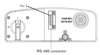
RS485-Schnittstellen, von denen bekannt ist, dass sie funktionieren:
DTECH DT-5019 USB zu RS-485 Konverter Adapter:
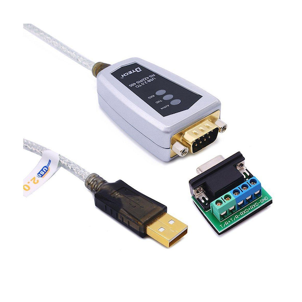
Um eine serielle Verbindung der Hauptplatine oder eine serielle Karte (RS232) in RS485 umzuwandeln, sind folgende Schritte erforderlich:
DTECH RS-232 zu RS-485 Konverter:

Beispiel einer seriellen Karte (Sunnix SER5037A PCI-Karte mit Breakout Board):
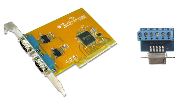
17.7. Lichtbogen OK mit einem Reed-Relais
Eine effektive und sehr zuverlässige Methode, um ein Lichtbogen-OK-Signal von einer Plasmaversorgung ohne CNC-Anschluss zu erhalten, besteht darin, ein Reed-Relais in einer nicht leitenden Röhre zu montieren und drei Windungen des Arbeitskabels um die Röhre zu wickeln und zu sichern.
Diese Baugruppe fungiert nun als Relais, das sich einschaltet, wenn Strom durch die Arbeitsleitung fließt, was nur dann der Fall ist, wenn sich ein Lichtbogen gebildet hat.
This will require that QtPlasmaC be operated in Mode 1 rather than Mode 0. See the QtPlasmaC Modes sections for more information.
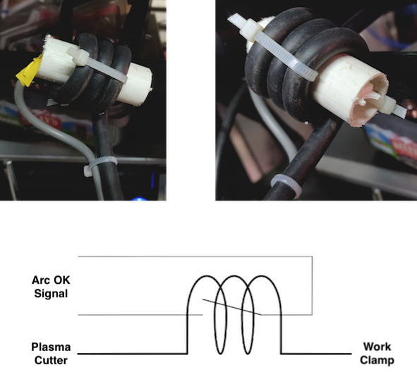

18. Bekannte Probleme
18.1. Tastatur-Jogging
There is a known issue with some combinations of hardware and keyboards that may affect the autorepeat feature of the keyboard and will then affect keyboard jogging by intermittent stopping and starting during jogging. This issue can be prevented by disabling the Operating System’s autorepeat feature for all keys. QtPlasmaC uses this disabling feature by default for all keys only when the MAIN Tab is visible, with the following exceptions when autorepeat is allowed with the MAIN Tab visible: G-code editor is active, MDI is active. When QtPlasmaC is shut down, the Operating System’s autorepeat feature will be enabled for all keys.
If the user wishes to prevent QtPlasmaC from changing the Operating System’s autorepeat settings, enter the following option in the [GUI_OPTIONS] section of the <machine_name>.prefs file:
Autorepeat all == True
Dieses Problem betrifft nicht das Joggen mit den GUI-Jog-Tasten.
|
Anmerkung
|
Das Trennen und erneute Anschließen einer Tastatur während einer aktiven QtPlasmaC-Sitzung führt dazu, dass sich die Autorepeat-Funktion automatisch wieder aktiviert, was zu einem unregelmäßigen Anhalten und Starten während des Joggens führen kann. Der Benutzer muss QtPlasmaC neu starten, um die Autorepeat-Funktion wieder zu deaktivieren. |
19. Unterstützung
Online-Hilfe und -Unterstützung finden Sie unter PlasmaC section des LinuxCNC Forum.
The user can create a compressed file containing the complete machine configuration to aid in fault diagnosis by pressing following the directions in the backup section. The resulting file is suitable for attaching to a post on the LinuxCNC Forum to help the community diagnose specific issues.