1. Einführung
Die Konfiguration geht von der Theorie zum Gerät über - dem HAL-Gerät. Für diejenigen, die nur ein wenig Erfahrung mit Computerprogrammierung haben, ist dieser Abschnitt das "Hello World" des HAL.
halrun kann verwendet werden, um ein funktionierendes System zu erstellen. Es ist ein Kommandozeilen- oder Textdateiwerkzeug für Konfiguration und Tuning.
2. Halcmd
halcmd ist ein Befehlszeilentool zum Manipulieren von HAL. Eine vollständigere Manpage existiert für halcmd und wird zusammen mit LinuxCNC installiert, aus dem Quellcode oder aus einem Paket. Wenn LinuxCNC als run-in-place kompiliert wurde, wird die Manpage nicht installiert, ist aber im LinuxCNC-Hauptverzeichnis mit dem folgenden Befehl zugänglich:
$ man -M docs/man halcmd2.1. Notation
For this tutorial, commands for the operating system are typically shown without the prompt provided by the UNIX shell, i.e typically a dollar sign ($) or a hash/double cross (#). When communicating directly with the HAL through halcmd or halrun, the prompts are shown in the examples. The terminal window is in Applications/Accessories from the main Ubuntu menu bar.
me@computer:~linuxcnc$ halrun
(wird wie die folgende Zeile angezeigt)
halrun

(die halcmd: Eingabeaufforderung wird beim Ausführen von HAL angezeigt)
halcmd: loadrt Zähler
halcmd: pin anzeigen
2.2. Befehl-Vervollständigung durch Tabulator-Taste
Your version of halcmd may include tab-completion. Instead of completing file names as a shell does, it completes commands with HAL identifiers. You will have to type enough letters for a unique match. Try pressing tab after starting a HAL command:
halcmd: loa<TAB>
halcmd: load
halcmd: loadrt
halcmd: loadrt cou<TAB>
halcmd: loadrt counter
2.3. Die RTAPI-Umgebung
RTAPI stands for Real Time Application Programming Interface. Many HAL components work in realtime, and all HAL components store data in shared memory so realtime components can access it. Regular Linux does not support realtime programming or the type of shared memory that HAL needs. Fortunately, there are realtime operating systems (RTOS’s) that provide the necessary extensions to Linux. Unfortunately, each RTOS does things a little differently.
Um diese Unterschiede zu beseitigen, hat das LinuxCNC-Team die RTAPI entwickelt, die einen einheitlichen Weg für Programme bietet, um mit dem RTOS zu kommunizieren. Wenn Sie ein Programmierer sind, der an den Interna von LinuxCNC arbeiten will, sollten Sie vielleicht linuxcnc/src/rtapi/rtapi.h studieren, um die API zu verstehen. Aber wenn Sie eine normale Person sind, ist alles, was Sie über RTAPI wissen müssen, dass es (und das RTOS) in den Speicher Ihres Computers geladen werden muss, bevor Sie etwas mit HAL machen.
3. Ein einfaches Beispiel
3.1. Laden einer Komponente
Für dieses Tutorial gehen wir davon aus, dass Sie die Live-CD erfolgreich installiert haben und, falls Sie eine RIP footnote: [Run In Place, wenn die Quelldateien in ein Benutzerverzeichnis heruntergeladen wurden und direkt von dort aus kompiliert und ausgeführt werden] Installation verwenden, das Skript "rip-environment" aufrufen, um Ihre Shell vorzubereiten. In diesem Fall müssen Sie nur noch die erforderlichen RTOS- und RTAPI-Module in den Speicher laden. Führen Sie einfach den folgenden Befehl in einem Terminalfenster aus:
cd linuxcnc
halrun
halcmd:
Nachdem das Echtzeitbetriebssystem und die RTAPI geladen sind, können wir mit dem ersten Beispiel beginnen. Beachten Sie, dass die Eingabeaufforderung jetzt als "halcmd:" angezeigt wird. Das liegt daran, dass die nachfolgenden Befehle als HAL-Befehle und nicht als Shell-Befehle interpretiert werden.
For the first example, we will use a HAL component called siggen, which is a simple signal generator. A complete description of the siggen component can be found in the SigGen section of this Manual. It is a realtime component. To load the "siggen" component, use the HAL command loadrt.
halcmd: loadrt siggen3.2. Untersuchung der HAL
Now that the module is loaded, it is time to introduce halcmd, the command line tool used to configure the HAL. This tutorial will introduce only a selection of halcmd features. For a more complete description try man halcmd, or see the reference in HAL Commands section of this document. The first halcmd feature is the show command. This command displays information about the current state of the HAL. To show all installed components:
halrun/halcmdhalcmd: show comp
Loaded HAL Components:
ID Type Name PID State
3 RT siggen ready
2 User halcmd2177 2177 readySince halcmd itself is also a HAL component, it will always show up in the list. The number after "halcmd" in the component list is the UNIX process ID. It is possible to run more than one copy of halcmd at the same time (in different terminal windows for example), so the PID is added to the end of the name to make it unique. The list also shows the siggen component that we installed in the previous step. The RT under Type indicates that siggen is a realtime component. The User under Type indicates it is a non-realtime component.
Next, let’s see what pins siggen makes available:
halcmd: show pin

Component Pins:
Owner   Type   Dir        Value  Name
     3  float  IN             1  siggen.0.amplitude
     3  bit    OUT        FALSE  siggen.0.clock
     3  float  OUT            0  siggen.0.cosine
     3  float  IN             1  siggen.0.frequency
     3  float  IN             0  siggen.0.offset
     3  float  OUT            0  siggen.0.sawtooth
     3  float  OUT            0  siggen.0.sine
     3  float  OUT            0  siggen.0.square
     3  float  OUT            0  siggen.0.triangle
This command displays all of the pins in the current HAL. A complex system could have dozens or hundreds of pins. But right now there are only nine pins. Of these pins eight are floating point and one is bit (boolean). Six carry data out of the siggen component and three are used to transfer settings into the component. Since we have not yet executed the code contained within the component, some the pins have a value of zero.
Der nächste Schritt ist die Betrachtung der Parameter:
halcmd: show param

Parameters:
Owner   Type  Dir        Value   Name
     3  s32   RO             0   siggen.0.update.time
     3  s32   RW             0   siggen.0.update.tmax
The show param command shows all the parameters in the HAL. Right now, each parameter has the default value it was given when the component was loaded. Note the column labeled Dir. The parameters labeled -W are writable ones that are never changed by the component itself, instead they are meant to be changed by the user to control the component. We will see how to do this later. Parameters labeled R- are read only parameters. They can be changed only by the component. Finally, parameter labeled RW are read-write parameters. That means that they are changed by the component, but can also be changed by the user. Note: The parameters siggen.0.update.time and siggen.0.update.tmax are for debugging purposes and won’t be covered in this section.
Most realtime components export one or more functions to actually run the realtime code they contain. Let’s see what function(s) siggen exported:
halcmd`halcmd: show funct
Exported Functions:
Owner CodeAddr Arg FP Users Name
00003 f801b000 fae820b8 YES 0 siggen.0.updateThe siggen component exported a single function. It requires floating point. It is not currently linked to any threads, so users is zero
[CodeAddr and Arg fields were used during development and should probably disappear.]
.
3.3. Echtzeitcode zum Laufen bringen
To actually run the code contained in the function siggen.0.update, we need a realtime thread. The component called threads that is used to create a new thread. Lets create a thread called "test-thread" with a period of 1 ms (1,000 µs or 1,000,000 ns):
halcmd: loadrt threads name1=test-thread period1=1000000Mal sehen, ob das funktioniert:
halcmd: show thread

Realtime Threads:
     Period  FP     Name               (     Time, Max-Time )
     999855  YES    test-thread        (        0,        0 )
It did. The period is not exactly 1,000,000 ns because of hardware limitations, but we have a thread that runs at approximately the correct rate, and which can handle floating point functions. The next step is to connect the function to the thread:
halcmd: addf siggen.0.update test-threadUp till now, we’ve been using halcmd only to look at the HAL. However, this time we used the addf (add function) command to actually change something in the HAL. We told halcmd to add the function siggen.0.update to the thread test-thread, and if we look at the thread list again, we see that it succeeded:
halcmd: show thread

Realtime Threads:
     Period  FP     Name                (     Time, Max-Time )
     999855  YES    test-thread         (        0,        0 )
                  1 siggen.0.update
There is one more step needed before the siggen component starts generating signals. When the HAL is first started, the thread(s) are not actually running. This is to allow you to completely configure the system before the realtime code starts. Once you are happy with the configuration, you can start the realtime code like this:
halcmd: startJetzt läuft der Signalgenerator. Schauen wir uns seine Ausgangspins an:
halcmd: show pin

Komponenten-Pins:
Owner   Type  Dir         Value  Name
     3  float IN              1  siggen.0.amplitude
     3  bit   OUT         FALSE  siggen.0.clock
     3  float OUT    -0.1640929  siggen.0.cosine
     3  float IN              1  siggen.0.frequency
     3  float IN              0  siggen.0.offset
     3  float OUT    -0.4475303  siggen.0.sawtooth
     3  float OUT     0.9864449  siggen.0.sine
     3  float OUT            -1  siggen.0.square
     3  float OUT    -0.1049393  siggen.0.triangle
Und schauen wir noch einmal hin:
halcmd: show pin

Komponenten Pins:
Owner   Type  Dir         Value  Name
     3  float IN              1  siggen.0.amplitude
     3  bit   OUT         FALSE  siggen.0.clock
     3  float OUT     0.0507619  siggen.0.cosine
     3  float IN              1  siggen.0.frequency
     3  float IN              0  siggen.0.offset
     3  float OUT     -0.516165  siggen.0.sawtooth
     3  float OUT     0.9987108  siggen.0.sine
     3  float OUT            -1  siggen.0.square
     3  float OUT    0.03232994  siggen.0.triangle
We did two show pin commands in quick succession, and you can see that the outputs are no longer zero. The sine, cosine, sawtooth, and triangle outputs are changing constantly. The square output is also working, however it simply switches from +1.0 to -1.0 every cycle.
3.4. Ändern von Parametern
The real power of HAL is that you can change things. For example, we can use the setp command to set the value of a parameter. Let’s change the amplitude of the signal generator from 1.0 to 5.0:
halcmd: setp siggen.0.amplitude 5halcmd: show param
Parameter:
Owner Type Dir Value Name
3 s32 RO 1754 siggen.0.update.time
3 s32 RW 16997 siggen.0.update.tmax
halcmd: show pin
Komponenten-Pins:
Owner Type Dir Value Name
3 float IN 5 siggen.0.amplitude
3 bit OUT FALSE siggen.0.clock
3 float OUT 0.8515425 siggen.0.cosine
3 float IN 1 siggen.0.frequency
3 float IN 0 siggen.0.offset
3 float OUT 2.772382 siggen.0.sawtooth
3 float OUT -4.926954 siggen.0.sine
3 float OUT 5 siggen.0.square
3 float OUT 0.544764 siggen.0.triangleNote that the value of parameter siggen.0.amplitude has changed to 5, and that the pins now have larger values.
3.5. Speichern der HAL-Konfiguration
Das meiste, was wir bisher mit halcmd gemacht haben, war einfach das Anzeigen von Dingen mit dem show-Befehl. Zwei der Befehle haben jedoch tatsächlich Dinge verändert. Wenn wir komplexere Systeme mit HAL entwerfen, werden wir viele Befehle verwenden, um die Dinge genau so zu konfigurieren, wie wir sie haben wollen. HAL hat ein Gedächtnis wie ein Elefant und behält diese Konfiguration bei, bis wir es abschalten. Aber was ist beim nächsten Mal? Wir wollen nicht jedes Mal, wenn wir das System benutzen wollen, eine Reihe von Befehlen manuell eingeben.
halcmd: save

# Komponenten
loadrt threads name1=test-thread period1=1000000
loadrt siggen
# Pin-Aliase
# Signale
# Netze
# Parameterwerte
setp siggen.0.update.tmax 14687
# Echtzeit-Thread/Funktions-Verknüpfungen
addf siggen.0.update test-thread
The output of the save command is a sequence of HAL commands. If you start with an empty HAL and run all these commands, you will get the configuration that existed when the save command was issued. To save these commands for later use, we simply redirect the output to a file:
halcmdhalcmd: save all saved.hal3.6. Halrun beenden
When you’re finished with your HAL session type exit at the "halcmd:" prompt. This will return you to the system prompt and close down the HAL session. Do not simply close the terminal window without shutting down the HAL session.
halcmd: exit3.7. Wiederherstellung der HAL-Konfiguration
To restore the HAL configuration stored in the file "saved.hal", we need to execute all of those HAL commands. To do that, we use "-f _<file name>_" which reads commands from a file, and "-I" (upper case i) which shows the halcmd prompt after executing the commands:
halrun -I -f saved.halNotice that there is not a "start" command in saved.hal. It’s necessary to issue it again (or edit the file saved.hal to add it there).
3.8. HAL aus dem Speicher entfernen
Wenn eine HAL-Sitzung unerwartet beendet wird, müssen Sie möglicherweise HAL entladen, bevor eine neue Sitzung beginnen kann. Geben Sie dazu den folgenden Befehl in ein Terminalfenster ein.
halrun -U4. Halmeter
Sie können sehr komplexe HAL-Systeme erstellen, ohne jemals eine grafische Oberfläche zu verwenden. Es hat jedoch etwas Befriedigendes, das Ergebnis seiner Arbeit zu sehen. Das erste und einfachste GUI-Werkzeug für HAL ist Halmeter. Es ist ein sehr einfaches Programm, das ein HAL-Äquivalent eines handlichen Multimeters darstellt.
It allows to observe the pins, signals or parameters by displaying the current value of these entities. It is very easy to use application for graphical environments. In a console type:
halmeterEs erscheinen zwei Fenster. Das Auswahlfenster ist das größte und enthält drei Registerkarten:
-
In der einen werden alle derzeit in HAL definierten Pins aufgelistet,
-
eine Liste aller Signale,
-
eine listet alle Parameter auf,
Klicken Sie auf eine Registerkarte und dann auf eines der Elemente, um es auszuwählen. In dem kleinen Fenster werden der Name und der Wert des ausgewählten Elements angezeigt. Die Anzeige wird etwa 10 Mal pro Sekunde aktualisiert. Um Platz auf dem Bildschirm zu schaffen, kann das Auswahlfenster mit der Schaltfläche Close geschlossen werden. Im kleinen Fenster, das beim Programmstart unter dem Auswahlfenster verborgen ist, öffnet die Schaltfläche Auswählen das Auswahlfenster erneut, und die Schaltfläche Beenden beendet das Programm und schließt beide Fenster.
Es ist möglich, mehrere Halmeter gleichzeitig laufen zu lassen, was die gleichzeitige Visualisierung mehrerer Elemente ermöglicht. Um ein Halmeter zu öffnen und die Konsole freizugeben, indem es im Hintergrund ausgeführt wird, führen Sie den folgenden Befehl aus:
halmeter &Es ist möglich, halmeter zu starten und sofort ein Element anzeigen zu lassen. Fügen Sie dazu pin|sig|par[am] name Argumente in die Befehlszeile ein. Es wird das Signal, den Pin oder den Parameter name anzeigen, sobald es startet. Wenn das angegebene Element nicht vorhanden ist, wird es normal gestartet.
Wenn ein Element für die Anzeige angegeben wird, kann man -s vor pin|sig|param hinzufügen, um Halmeter anzuweisen, ein noch kleineres Fenster zu verwenden. Der Name des Elements wird dann in der Titelleiste statt unter dem Wert angezeigt, und es gibt keine Schaltfläche. Dies ist nützlich, wenn viele Halmeter auf kleinem Raum angezeigt werden sollen.
Wir werden erneut die Komponente siggen verwenden, um halmeter zu überprüfen. Wenn Sie das vorherige Beispiel gerade beendet haben, können Sie siggen mit der gespeicherten Datei laden. Wenn nicht, können wir es genauso laden wie zuvor:
halrun
halcmd: loadrt siggen
halcmd: loadrt threads name1=test-thread period1=1000000
halcmd: addf siggen.0.update test-thread
halcmd: start
halcmd: setp siggen.0.amplitude 5
At this point we have the siggen component loaded and running. It’s time to start halmeter.
halcmd: loadusr halmeterThe first window you will see is the "Select Item to Probe" window.
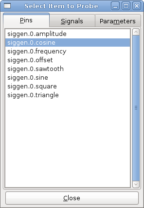
This dialog has three tabs. The first tab displays all of the HAL pins in the system. The second one displays all the signals, and the third displays all the parameters. We would like to look at the pin siggen.0.cosine first, so click on it then click the "Close" button. The probe selection dialog will close, and the meter looks something like the following figure.
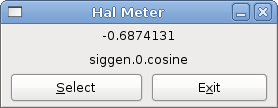
To change what the meter displays press the "Select" button which brings back the "Select Item to Probe" window.
Sie sollten sehen, wie sich der Wert ändert, wenn siggen seine Kosinuswelle erzeugt. Das Halmeter aktualisiert seine Anzeige etwa 5 Mal pro Sekunde.
Zum Beenden von Halmeter klicken Sie einfach auf die Schaltfläche Beenden.
Wenn Sie mehr als einen Pin, ein Signal oder einen Parameter auf einmal betrachten wollen, können Sie einfach mehrere Halmeter starten. Das Halmeter-Fenster wurde absichtlich sehr klein gehalten, damit Sie viele davon gleichzeitig auf dem Bildschirm haben können.
5. Stepgen Example
Bis jetzt haben wir nur eine HAL-Komponente geladen. Die Idee hinter HAL ist jedoch, dass Sie eine Reihe von einfachen Komponenten laden und verbinden können, um ein komplexes System zu bilden. Das nächste Beispiel wird zwei Komponenten verwenden.
Bevor wir mit der Erstellung dieses neuen Beispiels beginnen können, wollen wir einen Neuanfang machen. Wenn Sie gerade eines der vorherigen Beispiele beendet haben, müssen wir alle Komponenten entfernen und die RTAPI- und HAL-Bibliotheken neu laden.
halcmd: exit5.1. Installieren der Komponenten
Now we are going to load the step pulse generator component. For a detailed description of this component refer to the stepgen section of the Integrator Manual. In this example we will use the velocity control type of StepGen. For now, we can skip the details, and just run the following commands.
In diesem Beispiel wird der Kontrolltyp velocity aus der Komponente stepgen verwendet.
halrun
halcmd: loadrt stepgen step_type=0,0 ctrl_type=v,v
halcmd: loadrt siggen
halcmd: loadrt threads name1=fast fp1=0 period1=50000 name2=slow period2=1000000
The first command loads two step generators, both configured to generate stepping type 0. The second command loads our old friend siggen, and the third one creates two threads, a fast one with a period of 50 microseconds (µs) and a slow one with a period of 1 millisecond (ms). The fast thread doesn’t support floating point functions.
As before, we can use halcmd show to take a look at the HAL. This time we have a lot more pins and parameters than before:
halcmd: show pin

Component Pins:
Owner   Type  Dir         Value  Name
     4  float IN              1  siggen.0.amplitude
     4  bit   OUT         FALSE  siggen.0.clock
     4  float OUT             0  siggen.0.cosine
     4  float IN              1  siggen.0.frequency
     4  float IN              0  siggen.0.offset
     4  float OUT             0  siggen.0.sawtooth
     4  float OUT             0  siggen.0.sine
     4  float OUT             0  siggen.0.square
     4  float OUT             0  siggen.0.triangle
     3  s32   OUT             0  stepgen.0.counts
     3  bit   OUT         FALSE  stepgen.0.dir
     3  bit   IN          FALSE  stepgen.0.enable
     3  float OUT             0  stepgen.0.position-fb
     3  bit   OUT         FALSE  stepgen.0.step
     3  float IN              0  stepgen.0.velocity-cmd
     3  s32   OUT             0  stepgen.1.counts
     3  bit   OUT         FALSE  stepgen.1.dir
     3  bit   IN          FALSE  stepgen.1.enable
     3  float OUT             0  stepgen.1.position-fb
     3  bit   OUT         FALSE  stepgen.1.step
     3  float IN              0  stepgen.1.velocity-cmd

halcmd: show param

Parameters:
Owner   Type  Dir         Value  Name
     4  s32   RO              0  siggen.0.update.time
     4  s32   RW              0  siggen.0.update.tmax
     3  u32   RW     0x00000001  stepgen.0.dirhold
     3  u32   RW     0x00000001  stepgen.0.dirsetup
     3  float RO              0  stepgen.0.frequency
     3  float RW              0  stepgen.0.maxaccel
     3  float RW              0  stepgen.0.maxvel
     3  float RW              1  stepgen.0.position-scale
     3  s32   RO              0  stepgen.0.rawcounts
     3  u32   RW     0x00000001  stepgen.0.steplen
     3  u32   RW     0x00000001  stepgen.0.stepspace
     3  u32   RW     0x00000001  stepgen.1.dirhold
     3  u32   RW     0x00000001  stepgen.1.dirsetup
     3  float RO              0  stepgen.1.frequency
     3  float RW              0  stepgen.1.maxaccel
     3  float RW              0  stepgen.1.maxvel
     3  float RW              1  stepgen.1.position-scale
     3  s32   RO              0  stepgen.1.rawcounts
     3  u32   RW     0x00000001  stepgen.1.steplen
     3  u32   RW     0x00000001  stepgen.1.stepspace
     3  s32   RO              0  stepgen.capture-position.time
     3  s32   RW              0  stepgen.capture-position.tmax
     3  s32   RO              0  stepgen.make-pulses.time
     3  s32   RW              0  stepgen.make-pulses.tmax
     3  s32   RO              0  stepgen.update-freq.time
     3  s32   RW              0  stepgen.update-freq.tmax
5.2. Verbinden von Pins mit Signalen
Wir haben also zwei Schrittimpulsgeneratoren und einen Signalgenerator. Nun ist es an der Zeit, einige HAL-Signale zu erzeugen, um die beiden Komponenten zu verbinden. Wir tun so, als ob die beiden Schrittimpulsgeneratoren die X- und Y-Achse einer Maschine antreiben würden. Wir wollen den Tisch im Kreis bewegen. Dazu senden wir ein Kosinussignal an die X-Achse und ein Sinussignal an die Y-Achse. Das siggen-Modul erzeugt den Sinus und den Cosinus, aber wir brauchen "Drähte", um die Module miteinander zu verbinden. Im HAL werden diese "Drähte" Signale genannt. Wir müssen zwei davon erstellen. Wir können sie nennen, wie wir wollen, in diesem Beispiel werden sie X-vel und Y-vel heißen. Das Signal "X-vel" soll vom Cosinus-Ausgang des Signalgenerators zum Geschwindigkeitseingang des ersten Schrittimpulsgenerators führen. Der erste Schritt besteht darin, das Signal mit dem Ausgang des Signalgenerators zu verbinden. Um ein Signal mit einem Pin zu verbinden, verwenden wir den Netzbefehl.
halcmd: net X-vel <= siggen.0.cosineTo see the effect of the net command, we show the signals again.
halcmd: show sig

Signals:
Type          Value  Name     (linked to)
float             0  X-vel <== siggen.0.cosine
When a signal is connected to one or more pins, the show command lists the pins immediately following the signal name. The arrow shows the direction of data flow - in this case, data flows from pin siggen.0.cosine to signal X-vel. Now let’s connect the X-vel to the velocity input of a step pulse generator.
halcmd: net X-vel => stepgen.0.velocity-cmdWe can also connect up the Y axis signal Y-vel. It is intended to run from the sine output of the signal generator to the input of the second step pulse generator. The following command accomplishes in one line what two net commands accomplished for X-vel.
halcmd: net Y-vel siggen.0.sine => stepgen.1.velocity-cmdWerfen wir nun einen letzten Blick auf die Signale und die mit ihnen verbundenen Pins.
halcmd: show sig

Signals:
Type          Value  Name     (linked to)
float             0  X-vel <== siggen.0.cosine
                           ==> stepgen.0.velocity-cmd
float             0  Y-vel <== siggen.0.sine
                           ==> stepgen.1.velocity-cmd
The show sig command makes it clear exactly how data flows through the HAL. For example, the X-vel signal comes from pin siggen.0.cosine, and goes to pin stepgen.0.velocity-cmd.
5.3. Einrichten der Echtzeitausführung - Threads und Funktionen
Thinking about data flowing through "wires" makes pins and signals fairly easy to understand. Threads and functions are a little more difficult. Functions contain the computer instructions that actually get things done. Thread are the method used to make those instructions run when they are needed. First let’s look at the functions available to us.
halcmd: show funct

Exported Functions:
Owner   CodeAddr  Arg       FP   Users  Name
 00004  f9992000  fc731278  YES      0   siggen.0.update
 00003  f998b20f  fc7310b8  YES      0   stepgen.capture-position
 00003  f998b000  fc7310b8  NO       0   stepgen.make-pulses
 00003  f998b307  fc7310b8  YES      0   stepgen.update-freq
In general, you will have to refer to the documentation for each component to see what its functions do. In this case, the function siggen.0.update is used to update the outputs of the signal generator. Every time it is executed, it calculates the values of the sine, cosine, triangle, and square outputs. To make smooth signals, it needs to run at specific intervals.
Die anderen drei Funktionen beziehen sich auf die Schrittimpulsgeneratoren.
The first one, stepgen.capture_position, is used for position feedback. It captures the value of an internal counter that counts the step pulses as they are generated. Assuming no missed steps, this counter indicates the position of the motor.
The main function for the step pulse generator is stepgen.make_pulses. Every time make_pulses runs it decides if it is time to take a step, and if so sets the outputs accordingly. For smooth step pulses, it should run as frequently as possible. Because it needs to run so fast, make_pulses is highly optimized and performs only a few calculations. Unlike the others, it does not need floating point math.
The last function, stepgen.update-freq, is responsible for doing scaling and some other calculations that need to be performed only when the frequency command changes.
Für unser Beispiel bedeutet dies, dass wir siggen.0.update mit einer moderaten Rate ausführen wollen, um die Sinus- und Kosinuswerte zu berechnen. Unmittelbar nachdem wir siggen.0.update ausgeführt haben, wollen wir stepgen.update_freq ausführen, um die neuen Werte in den Schrittimpulsgenerator zu laden. Schließlich müssen wir stepgen.make_pulses so schnell wie möglich ausführen, um gleichmäßige Impulse zu erhalten. Da wir keine Positionsrückmeldung verwenden, brauchen wir stepgen.capture_position überhaupt nicht auszuführen.
We run functions by adding them to threads. Each thread runs at a specific rate. Let’s see what threads we have available.
halcmd: show thread

Realtime Threads:
     Period  FP     Name               (     Time, Max-Time )
     996980  YES                  slow (        0,        0 )
      49849  NO                   fast (        0,        0 )
The two threads were created when we loaded threads. The first one, slow, runs every millisecond, and is capable of running floating point functions. We will use it for siggen.0.update and stepgen.update_freq. The second thread is fast, which runs every 50 microseconds (µs), and does not support floating point. We will use it for stepgen.make_pulses. To connect the functions to the proper thread, we use the addf command. We specify the function first, followed by the thread.
halcmd: addf siggen.0.update slow
halcmd: addf stepgen.update-freq slow
halcmd: addf stepgen.make-pulses fast
After we give these commands, we can run the show thread command again to see what happened.
halcmd: show thread

Realtime Threads:
     Period  FP     Name               (     Time, Max-Time )
     996980  YES                  slow (        0,        0 )
                  1 siggen.0.update
                  2 stepgen.update-freq
      49849  NO                   fast (        0,        0 )
                  1 stepgen.make-pulses
Nun folgen auf jeden Thread die Namen der Funktionen in der Reihenfolge, in der sie ausgeführt werden sollen.
5.4. Parameter einstellen
We are almost ready to start our HAL system. However we still need to adjust a few parameters. By default, the siggen component generates signals that swing from +1 to -1. For our example that is fine, we want the table speed to vary from +1 to -1 inches per second. However the scaling of the step pulse generator isn’t quite right. By default, it generates an output frequency of 1 step per second with an input of 1.0. It is unlikely that one step per second will give us one inch per second of table movement. Let’s assume instead that we have a 5 turn per inch leadscrew, connected to a 200 step per rev stepper with 10x microstepping. So it takes 2000 steps for one revolution of the screw, and 5 revolutions to travel one inch. That means the overall scaling is 10000 steps per inch. We need to multiply the velocity input to the step pulse generator by 10000 to get the proper output. That is exactly what the parameter stepgen.n.velocity-scale is for. In this case, both the X and Y axis have the same scaling, so we set the scaling parameters for both to 10000.
halcmd: setp stepgen.0.position-scale 10000
halcmd: setp stepgen.1.position-scale 10000
halcmd: setp stepgen.0.enable 1
halcmd: setp stepgen.1.enable 1
This velocity scaling means that when the pin stepgen.0.velocity-cmd is 1.0, the step generator will generate 10000 pulses per second (10 kHz). With the motor and leadscrew described above, that will result in the axis moving at exactly 1.0 inches per second. This illustrates a key HAL concept - things like scaling are done at the lowest possible level, in this case in the step pulse generator. The internal signal X-vel is the velocity of the table in inches per second, and other components such as siggen don’t know (or care) about the scaling at all. If we changed the leadscrew, or motor, we would change only the scaling parameter of the step pulse generator.
5.5. Ausführen!
We now have everything configured and are ready to start it up. Just like in the first example, we use the start command.
halcmd: startAlthough nothing appears to happen, inside the computer the step pulse generator is cranking out step pulses, varying from 10 kHz forward to 10 kHz reverse and back again every second. Later in this tutorial we’ll see how to bring those internal signals out to run motors in the real world, but first we want to look at them and see what is happening.
6. Halscope
Das vorherige Beispiel erzeugt einige sehr interessante Signale. Aber vieles von dem, was passiert, ist viel zu schnell, um es mit dem Halmeter zu sehen. Um einen genaueren Blick auf die Vorgänge im Inneren des HAL zu werfen, brauchen wir ein Oszilloskop. Glücklicherweise verfügt HAL über ein solches, genannt halscope.
Halscope has two parts - a realtime part that reads the HAL signals, and a non-realtime part that provides the GUI and display. However, you don’t need to worry about this because the non-realtime part will automatically load the realtime part when needed.
With LinuxCNC running in a terminal you can start halscope with the following command.
halcmd loadusr halscopeWenn LinuxCNC nicht läuft oder die Datei autosave.halscope nicht mit den Pins übereinstimmt, die im aktuell laufenden LinuxCNC verfügbar sind, öffnet sich das Scope-GUI-Fenster, unmittelbar gefolgt von einem Dialog Realtime function not linked, der wie die folgende Abbildung aussieht. Um die Abtastrate zu ändern, klicken Sie mit der linken Maustaste auf das Feld Samples.
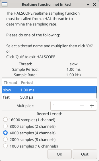
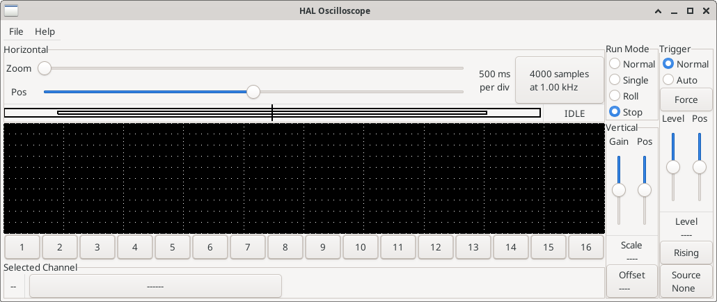
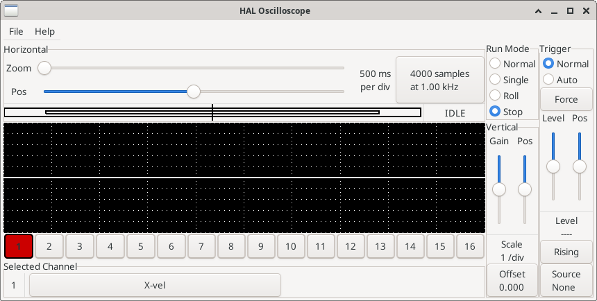
This dialog is where you set the sampling rate for the oscilloscope. For now we want to sample once per millisecond, so click on the 1.00 ms thread slow and leave the multiplier at 1. We will also leave the record length at 4000 samples, so that we can use up to four channels at one time. When you select a thread and then click OK, the dialog disappears, and the scope window looks something like the following figure.
6.1. Anschließen der Oszilloskop-Sonden
An diesem Punkt ist Halscope einsatzbereit. Wir haben bereits eine Abtastrate und eine Aufzeichnungslänge gewählt, so dass der nächste Schritt darin besteht, zu entscheiden, was wir uns ansehen wollen. Dies ist gleichbedeutend mit dem Anschließen von "virtuellen Oszilloskop-Sonden" an den HAL. Halscope verfügt über 16 Kanäle, aber die Anzahl, die Sie gleichzeitig verwenden können, hängt von der Aufzeichnungslänge ab - mehr Kanäle bedeuten kürzere Aufzeichnungen, da der für die Aufzeichnung verfügbare Speicher auf etwa 16.000 Samples festgelegt ist.
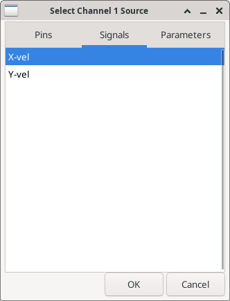
Die Kanalschaltflächen befinden sich am unteren Rand des Halskop-Bildschirms. Wenn Sie auf die Schaltfläche "1" klicken, wird das Dialogfeld "Select Channel Source" (Kanalquelle auswählen) angezeigt, wie in der folgenden Abbildung dargestellt. Dieser Dialog ist dem von Halmeter verwendeten Dialog sehr ähnlich. Wir möchten uns die Signale ansehen, die wir zuvor definiert haben, also klicken wir auf die Registerkarte "Signale", und der Dialog zeigt alle Signale im HAL an (in diesem Beispiel nur zwei).
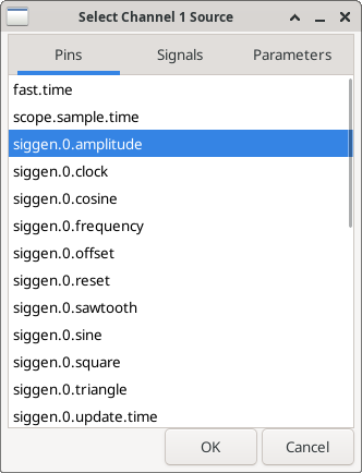
Um ein Signal auszuwählen, klicken Sie es einfach an. In diesem Fall möchten wir, dass auf Kanal 1 das Signal "X-vel" angezeigt wird. Klicken Sie auf die Registerkarte "Signale" und dann auf "X-vel". Das Dialogfeld schließt sich und der Kanal ist nun ausgewählt.
Die Taste für Kanal 1 wird gedrückt, und die Kanalnummer 1 und die Bezeichnung "X-vel" erscheinen unter der Tastenreihe. Diese Anzeige zeigt immer den ausgewählten Kanal an - Sie können mehrere Kanäle auf dem Bildschirm haben, aber der ausgewählte Kanal ist hervorgehoben, und die verschiedenen Steuerelemente wie vertikale Position und Skalierung funktionieren immer für den ausgewählten Kanal.
To add a signal to channel 2, click the 2 button. When the dialog pops up, click the Signals tab, then click on Y-vel. We also want to look at the square and triangle wave outputs. There are no signals connected to those pins, so we use the Pins tab instead. For channel 3, select siggen.0.triangle and for channel 4, select siggen.0.square.
6.2. Erfassen unserer ersten Wellenformen
Nachdem wir nun mehrere Sonden an den HAL angeschlossen haben, ist es an der Zeit, einige Wellenformen zu erfassen. Zum Starten des Oszilloskops klicken Sie auf die Schaltfläche "Normal" im Abschnitt "Run Mode" des Bildschirms (oben rechts). Da wir eine Aufzeichnungslänge von 4000 Samples haben und 1000 Samples pro Sekunde erfassen, wird halscope etwa 2 Sekunden brauchen, um die Hälfte seines Puffers zu füllen. Während dieser Zeit zeigt ein Fortschrittsbalken direkt über dem Hauptbildschirm an, dass der Puffer gefüllt ist. Sobald der Puffer halb voll ist, wartet das Scope auf einen Trigger. Da wir noch keinen konfiguriert haben, wird es ewig warten. Um es manuell auszulösen, klicken Sie auf die Schaltfläche "Erzwingen" im Abschnitt "Auslöser" oben rechts. Sie sollten sehen, wie sich der Rest des Puffers füllt, und dann werden die erfassten Wellenformen auf dem Bildschirm angezeigt. Das Ergebnis sieht ungefähr so aus wie in der folgenden Abbildung.
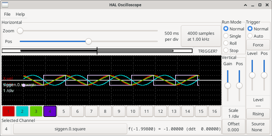
The Selected Channel box at the bottom tells you that the purple trace is the currently selected one, channel 4, which is displaying the value of the pin siggen.0.square. Try clicking channel buttons 1 through 3 to highlight the other three traces.
6.3. Vertikale Anpassungen
Die Spuren sind nur schwer zu unterscheiden, da alle vier übereinander liegen. Um dies zu beheben, verwenden wir die "Vertikal"-Steuerungen in der Box auf der rechten Seite des Bildschirms. Diese Regler wirken sich auf den aktuell ausgewählten Kanal aus. Bei der Einstellung der Verstärkung ist zu beachten, dass sie einen riesigen Bereich abdeckt - im Gegensatz zu einem echten Oszilloskop kann dieses Gerät Signale von sehr kleinen (Pico-Einheiten) bis zu sehr großen (Tera-Einheiten) anzeigen. Mit dem Positionsregler wird die angezeigte Kurve nur über die Höhe des Bildschirms nach oben und unten bewegt. Für größere Einstellungen sollte die Offset-Taste verwendet werden.

Die große Schaltfläche Ausgewählter Kanal am unteren Rand zeigt an, dass Kanal 1 der aktuell ausgewählte Kanal ist und dass er mit dem X-vel-Signal übereinstimmt. Versuchen Sie, auf die anderen Kanäle zu klicken, um ihre Spuren sichtbar zu machen und sie mit dem Pos-Cursor verschieben zu können.
6.4. Triggering (automatisches Auslösen)
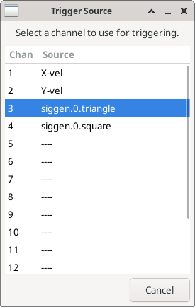
Die Verwendung des Button "Erzwingen" ist eine eher unbefriedigende Art, das Oszilloskop auszulösen. Um eine echte Triggerung einzurichten, klicken Sie auf die Schaltfläche "Quelle" unten rechts. Daraufhin wird das Dialogfeld "Trigger Source" (Triggerquelle) angezeigt, das einfach eine Liste aller derzeit angeschlossenen Sonden enthält. Wählen Sie eine Sonde für die Triggerung aus, indem Sie auf sie klicken. In diesem Beispiel verwenden wir Kanal 3, die Dreieckswelle, wie in der folgenden Abbildung dargestellt.
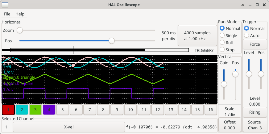
Nachdem Sie die Triggerquelle eingestellt haben, können Sie den Triggerpegel und die Triggerposition mit den Schiebereglern im Feld "Trigger" am rechten Rand einstellen. Der Pegel kann vom oberen bis zum unteren Rand des Bildschirms eingestellt werden und wird unter den Schiebereglern angezeigt. Die Position ist die Lage des Auslösepunkts innerhalb der gesamten Aufzeichnung. Ist der Schieberegler ganz unten, befindet sich der Auslösepunkt am Ende der Aufzeichnung, und halscope zeigt an, was vor dem Auslösepunkt passiert ist. Wenn der Schieberegler ganz nach oben geschoben ist, befindet sich der Auslösepunkt am Anfang des Datensatzes und es wird angezeigt, was nach dem Auslösen passiert ist. Der Triggerpunkt ist als vertikale Linie in der Fortschrittsanzeige über dem Bildschirm sichtbar. Die Triggerpolarität kann durch Klicken auf die Schaltfläche direkt unter der Triggerpegelanzeige geändert werden. Sie wird dann absteigend. Beachten Sie, dass die Änderung der Triggerposition das Oszilloskop anhält, sobald die Position angepasst wurde, starten Sie das Oszilloskop erneut, indem Sie auf die Schaltfläche Normal des Run-Modus der Gruppe klicken.
Nachdem wir nun die vertikalen Regler und die Triggerung eingestellt haben, sieht die Anzeige des Oszilloskops etwa wie in der folgenden Abbildung aus.
6.5. Horizontale Anpassungen
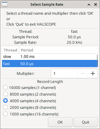
To look closely at part of a waveform, you can use the zoom slider at the top of the screen to expand the waveforms horizontally, and the position slider to determine which part of the zoomed waveform is visible. However, sometimes simply expanding the waveforms isn’t enough and you need to increase the sampling rate. For example, we would like to look at the actual step pulses that are being generated in our example. Since the step pulses may be only 50 µs long, sampling at 1 kHz isn’t fast enough. To change the sample rate, click on the button that displays the number of samples and sample rate to bring up the Select Sample Rate dialog figure. For this example, we will click on the 50 µs thread, fast, which gives us a sample rate of about 20 kHz. Now instead of displaying about 4 seconds worth of data, one record is 4000 samples at 20 kHz, or about 0.20 seconds.
6.6. Weitere Kanäle
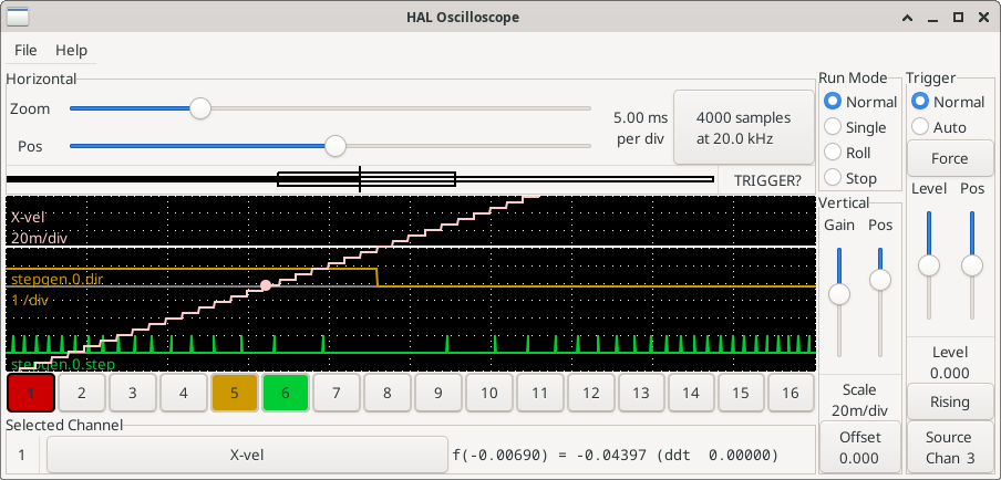
Now let’s look at the step pulses. Halscope has 16 channels, but for this example we are using only 4 at a time. Before we select any more channels, we need to turn off a couple. Clicking on a selected channel button (black border) will turn the channel off. So click on the channel 2 button, then click again on this button and the channel will turn off. Then click twice on channel 3 and do the same for channel 4. Even though the channels are turned off, they still remember what they are connected to, and in fact we will continue to use channel 3 as the trigger source. To add new channels, select channel 5, and choose pin stepgen.0.dir, then channel 6, and select stepgen.0.step. Then click run mode Normal to start the scope, and adjust the horizontal zoom to 5 ms per division. You should see the step pulses slow down as the velocity command (channel 1) approaches zero, then the direction pin changes state and the step pulses speed up again. You might want toincrease the gain on channel 1 to about 20 milli per division to better see the change in the velocity command. The result should look like the following figure.
6.7. Weitere Samples
Wenn Sie mehr Samples auf einmal aufnehmen wollen, starten Sie realtime neu und laden Sie halscope mit einem numerischen Argument, das die Anzahl der Samples angibt, die Sie aufnehmen wollen.
halcmd loadusr halscope 80000Wenn die Komponente scope_rt noch nicht geladen war, lädt halscope sie und fordert 80000 Gesamtsamples an, so dass bei der Abtastung von 4 Kanälen gleichzeitig 20000 Samples pro Kanal zur Verfügung stehen. (Wenn scope_rt bereits geladen war, hat das numerische Argument für halscope keine Auswirkungen).