1. Descripción general
The LinuxCNC G-code language is based on the RS274/NGC language. The G-code language is based on lines of code. Each line (also called a block) may include commands to do several different things. Lines of code may be collected in a file to make a program.
A typical line of code consists of an optional line number at the beginning followed by one or more words. A word consists of a letter followed by a number (or something that evaluates to a number). A word may either give a command or provide an argument to a command. For example, G1 X3 is a valid line of code with two words. G1 is a command meaning move in a straight line at the programmed feed rate to the programmed end point, and X3 provides an argument value (the value of X should be 3 at the end of the move). Most LinuxCNC G-code commands start with either G or M (for General and Miscellaneous). The words for these commands are called G-codes and M-codes. Also common are subroutine codes that begin with o- which are called o-codes.
El lenguaje LinuxCNC no tiene indicador para el inicio de un programa. El intérprete, sin embargo, se ocupa de los archivos. Un solo programa puede estar en un archivo único, o un programa puede extenderse a través de varios archivos. Un archivo se puede demarcar con porcentajes de la siguiente manera. La primera linea no en blanco de un archivo puede contener solo un signo de porcentaje, %, posiblemente rodeado de espacios en blanco y luego (normalmente al final del archivo) puede haber una línea similar. Demarcar un archivo con porcentajes es opcional si el archivo tiene un M2 o M30, pero es requerido si no los tiene. Se notificará un error si un archivo tiene una línea de porcentaje al principio pero no al final. El contenido util de un archivo delimitado por porcentajes termina después de la segunda línea porcentaje. Cualquier cosa después de eso, se ignora.
The LinuxCNC G-code language has two commands (M2 or M30), either of which ends a program. A program may end before the end of a file. Lines of a file that occur after the end of a program are not to be executed. The interpreter does not even read them.
2. Format of a line
Una línea permitida de código de entrada consiste en lo siguiente, en orden, con la restricción de que hay un máximo (actualmente 256) al número de caracteres permitidos en una línea.
-
an optional block delete character, which is a slash /.
-
an optional line number.
-
Any number of:
-
words,
-
parameter settings,
-
subroutine codes, and
-
comentarios.
-
-
an end of line marker (carriage return or line feed or both).
Any input not explicitly allowed is illegal and will cause the Interpreter to signal an error.
Spaces and tabs are allowed anywhere on a line of code and do not change the meaning of the line, except inside comments. This makes some strange-looking input legal. The line G0X +0. 12 34Y 7 is equivalent to G0 x+0.1234 Y7, for example.
Blank lines are allowed in the input. They are to be ignored.
La entrada no distingue entre mayúsculas y minúsculas, excepto en los comentarios, es decir, cualquier letra fuera de un comentario puede estar en mayúsculas o minúsculas sin cambiar el significado de una línea.
2.1. /: Block Delete
El carácter opcional de eliminación de bloque es la barra / cuando se coloca al principio de una línea. Algunas interfaces de usuario pueden utilizarlo para omitir líneas de código cuando sea necesario. En Axis, la combinación de teclas Alt-m-/ activa o desactiva la eliminación de bloque. Cuando eliminar bloque está activado, cualquier línea que comience con la barra / se omite.
In AXIS, it is also possible to enable block delete with the following icon:

2.2. Número de línea opcional
Un número de línea es la letra N seguida de un entero sin signo, seguida opcionalmente por un punto y otro entero sin signo. Por ejemplo, N1234 y N56.78 son números de línea válidos. Pueden ser repetidos o usados fuera de orden, aunque la práctica normal es evitar tal uso. Los números de línea también se pueden omitir, y eso es la práctica normal. No es necesario utilizar un número de línea, pero debe estar en el lugar apropiado si se usa.
|
Nota
|
Line numbers are not recommended. See Best Practices. |
2.3. Words, Parameters, Subroutines, Comments
2.3.1. Words
A word is a letter other than N or O ("o") followed by a real value.
Words may begin with any of the letters shown in the following Table. The table includes N and O for completeness, even though, as defined above, line numbers and program flow parameters are not words. Several letters (I, J, K, L, P, R) may have different meanings in different contexts. Letters which refer to axis names are not valid on a machine which does not have the corresponding axis.
| Letter | Meaning |
|---|---|
A |
A axis of machine |
B |
B axis of machine |
C |
C axis of machine |
D |
Tool radius compensation number |
F |
Velocidad de alimentación |
G |
General function (See table G-code Modal Groups) |
H |
Índice de desplazamiento de la longitud de la herramienta |
I |
Offset X para arcos y ciclos fijos G87 |
J |
Offset Y para arcos y ciclos fijos G87 |
K |
Z offset for arcs and G87 canned cycles. |
Spindle-Motion Ratio for G33 synchronized movements. |
|
L |
generic parameter word for G10, M66 and others |
M |
Miscellaneous function (See table M-code Modal Groups) |
N |
Line number (not recommended, see Best Practices) |
O |
o-codes for program flow control (See o-Codes) |
P |
Dwell time in canned cycles and with G4. |
Key used with G10. |
|
Q |
Feed increment in G73, G83 canned cycles |
R |
Radio del arco o plano del ciclo fijo |
S |
Spindle speed |
T |
Tool selection |
U |
U axis of machine |
V |
V axis of machine |
W |
W axis of machine |
X |
X axis of machine |
Y |
Y axis of machine |
Z |
Z axis of machine |
2.3.2. Parámetros
Parameters are identified with a "#" symbol in front of them. See Parameters Section below.
2.3.3. Subroutine Codes
Also called o-codes these provide program flow control (such as if-else logic and callable subroutines) and are covered fully at the page on o-Codes and also below in Subroutine Codes and Parameters.
|
Nota
|
o-codes are sometimes also called o-words. |
2.3.4. Comentarios
Comments can be embedded in a line using parentheses () or for the remainder of a line using a semi-colon. There are also active comments like MSG, DEBUG, etc. See the section on comments.
2.4. End of Line Marker
This is any combination of carriage return or line feed.
3. Numbers
The following rules are used for (explicit) numbers. In these rules a digit is a single character between 0 and 9.
-
A number consists of:
-
an optional plus or minus sign, followed by
-
zero to many digits, followed, possibly, by
-
one decimal point, followed by
-
zero to many digits - provided that there is at least one digit somewhere in the number.
-
-
There are two kinds of numbers:
-
enteros, que no tienen un punto decimal en él,
-
Decimals, that do have a decimal point.
-
-
Numbers may have any number of digits, subject to the limitation on line length. Only about seventeen significant figures will be retained, however (enough for all known applications).
-
A non-zero number with no sign but the first character is assumed to be positive.
Observe que los ceros inicial (antes del punto decimal y el primer dígito distinto de cero) y final (después del punto decimal y el último dígito distinto de cero) están permitidos pero no son obligatorios. Un número escrito con los ceros iniciales o finales tendrán el mismo valor cuando se lea como si los ceros adicionales no estuvieran allí.
Numbers used for specific purposes in RS274/NGC are often restricted to some finite set of values or some to some range of values. In many uses, decimal numbers must be close to integers; this includes the values of indices (for parameters and carousel slot numbers, for example), M-codes, and G-codes multiplied by ten. A decimal number which is intended to represent an integer is considered close enough if it is within 0.0001 of an integer value.
4. Parámetros
The RS274/NGC language supports parameters - what in other programming languages would be called variables. There are several types of parameter of different purpose and appearance, each described in the following sections. The only value type supported by parameters is floating-point; there are no string, boolean or integer types in G-code like in other programming languages. However, logic expressions can be formulated with boolean operators ( AND, OR, XOR, and the comparison operators EQ,NE,GT,GE,LT,LE), and the MOD, ROUND, FUP and FIX operators support integer arithmetic.
Parameters differ in syntax, scope, behavior when not yet initialized, mode, persistence and intended use.
- Sintaxis
-
There are three kinds of syntactic appearance:
-
numbered - #4711
-
named local - #<localvalue>
-
named global - #<_globalvalue>
-
- Scope
-
The scope of a parameter is either global, or local within a subroutine. Subroutine parameters and local named variables have local scope. Global named parameters and numbered parameters starting from number 31 are global in scope. RS274/NGC uses lexical scoping - in a subroutine only the local variables defined therein, and any global variables are visible. The local variables of a calling procedure are not visible in a called procedure.
- Behavior of uninitialized parameters
-
-
Uninitialized global parameters, and unused subroutine parameters return the value zero when used in an expression.
-
Uninitialized named parameters signal an error when used in an expression.
-
- Modo
-
Most parameters are read/write and may be assigned to within an assignment statement. However, for many predefined parameters this does not make sense, so they are are read-only - they may appear in expressions, but not on the left-hand side of an assignment statement.
- Persistence
-
Cuando LinuxCNC se cierra, los parámetros volátiles pierden su valores. Todos los parámetros excepto los parámetros numerados en el actual rango persistente
[persistent_range,El rango de parámetros persistentes puede cambiar a medida que avanza el desarrollo. Este rango es actualmente 5161-5390. Se define en required_parameters array en el archivo src/emc/rs274ngc/interp_array.cc.]
son volátiles. Los parámetros persistentes se guardan en el archivo .var y son restaurados a sus valores anteriores cuando LinuxCNC se inicia de nuevo. Los parámetros numerados volatiles se restablecen a cero. - Intended Use
-
-
parámetros de usuario - parámetros numerados en el rango 31..5000, y parámetros nombrados globales y locales, excepto parámetros predefinidos. Estan disponible para almacenamiento de uso general de valores de punto flotante, como resultados intermedios, banderas, etc., a lo largo de la ejecución del programa. Son de lectura/escritura (se le puede asignar un valor).
-
parámetros de subrutina - se utilizan para mantener los parámetros reales pasados a una subrutina.
-
numbered parameters - most of these are used to access offsets of coordinate systems.
-
system parameters - used to determine the current running version. They are read-only.
-
4.1. Numbered Parameters
A numbered parameter is the pound character # followed by an integer between 1 and (currently) 5602
[The RS274/NGC interpreter maintains an array of numbered parameters. Its size is defined by the symbol RS274NGC_MAX_PARAMETERS in the file src/emc/rs274ngc/interp_internal.hh). This number of numerical parameters may also increase as development adds support for new parameters.]
. The parameter is referred to by this integer, and its value is whatever number is stored in the parameter.
A value is stored in a parameter with the = operator; for example:
#3 = 15 (set parameter 3 to 15)A parameter setting does not take effect until after all parameter values on the same line have been found. For example, if parameter 3 has been previously set to 15 and the line #3=6 G1 X#3 is interpreted, a straight move to a point where X equals 15 will occur and the value of parameter 3 will be 6.
The # character takes precedence over other operations, so that, for example, #1+2 means the number found by adding 2 to the value of parameter 1, not the value found in parameter 3. Of course, #[1+2] does mean the value found in parameter 3. The # character may be repeated; for example ##2 means the value of the parameter whose index is the (integer) value of parameter 2.
-
31-5000 - G-code user parameters. These parameters are global in the G code file, and available for general use. Volatile.
-
5061-5069 - Coordinates of a G38 probe result (X, Y, Z, A, B, C, U, V & W). Coordinates are in the coordinate system in which the G38 took place. Volatile.
-
5070 - G38 probe result: 1 if success, 0 if probe failed to close. Used with G38.3 and G38.5. Volatile.
-
5161-5169 - "G28" Home for X, Y, Z, A, B, C, U, V & W. Persistent.
-
5181-5189 - "G30" Home for X, Y, Z, A, B, C, U, V & W. Persistent.
-
5210 - 1 if "G52" or "G92" offset is currently applied, 0 otherwise. Persistent by default; volatile if DISABLE_G92_PERSISTENCE = 1 in the [RS274NGC] section of the INI file.
-
5211-5219 - Shared "G52" and "G92" offset for X, Y, Z, A, B, C, U, V & W. Volatile by default; persistent if DISABLE_G92_PERSISTENCE = 1 in the [RS274NGC] section of the INI file.
-
5220 - Coordinate System number 1 - 9 for G54 - G59.3. Persistent.
-
5221-5230 - Coordinate System 1, G54 for X, Y, Z, A, B, C, U, V, W & R. R denotes the XY rotation angle around the Z axis. Persistent.
-
5241-5250 - Coordinate System 2, G55 for X, Y, Z, A, B, C, U, V, W & R. Persistent.
-
5261-5270 - Coordinate System 3, G56 for X, Y, Z, A, B, C, U, V, W & R. Persistent.
-
5281-5290 - Coordinate System 4, G57 for X, Y, Z, A, B, C, U, V, W & R. Persistent.
-
5301-5310 - Coordinate System 5, G58 for X, Y, Z, A, B, C, U, V, W & R. Persistent.
-
5321-5330 - Coordinate System 6, G59 for X, Y, Z, A, B, C, U, V, W & R. Persistent.
-
5341-5350 - Coordinate System 7, G59.1 for X, Y, Z, A, B, C, U, V, W & R. Persistent.
-
5361-5370 - Coordinate System 8, G59.2 for X, Y, Z, A, B, C, U, V, W & R. Persistent.
-
5381-5390 - Coordinate System 9, G59.3 for X, Y, Z, A, B, C, U, V, W & R. Persistent.
-
5399 - Result of M66 - Check or wait for input. Volatile.
-
5400 - Tool Number. Volatile.
-
5401-5409 - Tool Offsets for X, Y, Z, A, B, C, U, V & W. Set by G43. Volatile.
-
5410 - Tool Diameter. Volatile.
-
5411 - Tool Front Angle. Volatile.
-
5412 - Tool Back Angle. Volatile.
-
5413 - Tool Orientation. Volatile.
-
5420-5428 - Current relative position in the active coordinate system including all offsets and in the current program units for X, Y, Z, A, B, C, U, V & W, volatile.
-
5599 - Flag for controlling the output of (DEBUG,) statements. 1=output, 0=no output; default=1. Volatile.
The values of parameters in the persistent range are retained over time, even if the machining center is powered down. LinuxCNC uses a parameter file to ensure persistence. It is managed by the Interpreter. The Interpreter reads the file when it starts up, and writes the file when it exits.
The format of a parameter file is shown in Table Parameter File Format.
El intérprete espera que el archivo tenga dos columnas. Se salta cualquier línea que no contenga exactamente dos valores numéricos. Se espera que la primera columna contenga un valor entero (el número de parámetro). La segunda columna contiene un número de punto flotante (último valor del parámetro). El valor se representa como un número de punto flotante de doble precisión dentro del intérprete, pero el punto decimal no se requiere en el archivo.
Pueden agregarse al archivo parámetros definidos por el usuario en el rango (31-5000). Dichos parámetros serán leídos por el intérprete y escritos en el archivo al salir.
Missing Parameters in the persistent range will be initialized to zero and written with their current values on the next save operation.
Los números de los parámetros deben organizarse en orden ascendente. Se señalará el error Archivo de parámetros desordenado si no están en orden ascendente.
The original file is saved as a backup file when the new file is written.
| Numeración de parámetros | Valor del parámetro |
|---|---|
5161 |
0.0 |
5162 |
0.0 |
4.2. Subroutine Codes and Parameters
Subroutine codes, or o-codes (sometimes also called o-words), provide for logic and flow control in NGC programs (as in if-else logic). They are called Subroutine codes because they can also form called subroutines (as in sub-endsub).
See the chapter on o-Codes.
|
Nota
|
If o-codes are used to form subroutines, then o-codes can also call those subroutines and pass up to 30 parameters, which are local to the subroutine and volatile. (Again, see o-Codes for fuller treatment and examples.) |
|
Nota
|
While both lower and upper case o- are valid, best practice is using lower case "o-" because it disambiguates 0 (zero) and O (capital o). |
4.3. Named Parameters
Named parameters work like numbered parameters but are easier to read. All parameter names are converted to lower case and have spaces and tabs removed, so <param> and <P a R am > refer to the same parameter. Named parameters must be enclosed with < > marks.
#<named parameter> is a local named parameter. By default, a named parameter is local to the scope in which it is assigned. You can’t access a local parameter outside of its subroutine. This means that two subroutines can use the same parameter names without fear of one subroutine overwriting the values in another.
#<_parámetro con nombre global> es un parámetro con nombre global. Son accesibles desde las subrutinas llamadas y pueden establecer valores dentro de subrutinas que serán accesibles para el llamante. En lo que respecta al alcance, actúan como parámetros numéricos regulares. No se almacenan en archivos.
Examples:
#<_endmill_dia> = 0.049#<_endmill_rad> = [#<_endmill_dia>/2.0]o100 call [0.0] [0.0] [#<_inside_cutout>-#<_endmill_dia>] [#<_Zcut>] [#<_feedrate>]Los parámetros con nombre aparecen cuando se les asigna un valor por primera vez. Los parámetros locales nombrados desaparecen cuando se abandona su alcance, esto es, cuando se vuelve de una subrutina se eliminan todos sus parámetros locales y ya no se puede hacer referencia a ellos.
It is an error to use a non-existent named parameter within an expression, or at the right-hand side of an assignment. Printing the value of a non-existent named parameter with a DEBUG statement - like (DEBUG, <no_such_parameter>) will display the string #.
Global parameters, as well as local parameters assigned to at the global level, retain their value once assigned even when the program ends, and have these values when the program is run again.
The EXISTS function tests whether a given named parameter exists.
4.4. Predefined Named Parameters
The following global read only named parameters are available to access internal state of the interpreter and machine state. They can be used in arbitrary expressions, for instance to control flow of the program with if-then-else statements. Note that new predefined named parameters can be added easily without changes to the source code.
-
#<_vmajor> - Major package version. If current version was 2.5.2 would return 2.5.
-
#<_vminor> - Minor package version. If current version was 2.6.2 it would return 0.2.
-
#<_line> - Sequence number. If running a G-code file, this returns the current line number.
-
#<_motion_mode> - Return the interpreter’s current motion mode:
| Motion mode | valor de retorno |
|---|---|
G1 |
10 |
G2 |
20 |
G3 |
30 |
G33 |
330 |
G38.2 |
382 |
G38.3 |
383 |
G38.4 |
384 |
G38.5 |
385 |
G5.2 |
52 |
G73 |
730 |
G76 |
760 |
G80 |
800 |
G81 |
810 |
G82 |
820 |
G83 |
830 |
G84 |
840 |
G85 |
850 |
G86 |
860 |
G87 |
870 |
G88 |
880 |
G89 |
890 |
-
#<_plane> - returns the value designating the current plane:
| Plane | valor de retorno |
|---|---|
G17 |
170 |
G18 |
180 |
G19 |
190 |
G17.1 |
171 |
G18.1 |
181 |
G19.1 |
191 |
-
#<_ccomp> - Status of cutter compensation. Return values:
| Modo | valor de retorno |
|---|---|
G40 |
400 |
G41 |
410 |
G41.1 |
411 |
G41 |
410 |
G42 |
420 |
G42.1 |
421 |
-
#<_metric> - Return 1 if G21 is on, else 0.
-
#<_imperial> - Return 1 if G20 is on, else 0.
-
#<_absolute> - Return 1 if G90 is on, else 0.
-
#<_incremental> - Return 1 if G91 is on, else 0.
-
#<_inverse_time> - Return 1 if inverse feed mode (G93) is on, else 0.
-
#<_units_per_minute> - Return 1 if Units/minute feed mode (G94) is on, else 0.
-
#<_units_per_rev> - Return 1 if Units/revolution mode (G95) is on, else 0.
-
#<_coord_system> - Return a float of the current coordinate system name (G54..G59.3). For example if your in G55 coordinate system the return value is 550.000000 and if your in G59.1 the return value is 591.000000.
| Modo | valor de retorno |
|---|---|
G54 |
540 |
G55 |
550 |
G56 |
560 |
G57 |
570 |
G58 |
580 |
G59 |
590 |
G59.1 |
591 |
G59.2 |
592 |
G59.3 |
593 |
-
#<_tool_offset> - Return 1 if tool offset (G43) is on, else 0.
-
#<_retract_r_plane> - Return 1 if G98 is set, else 0.
-
#<_retract_old_z> - Return 1 if G99 is on, else 0.
4.5. System Parameters
* <_spindle_rpm_mode> - Return 1 if spindle rpm mode (G97) is on, else 0. * <_spindle_css_mode> - Return 1 if constant surface speed mode (G96) is on, else 0. * <_ijk_absolute_mode> - Return 1 if Absolute Arc distance mode (G90.1) is on, else 0. * <_lathe_diameter_mode> - Return 1 if this is a lathe configuration and diameter (G7) mode is on, else 0. * <_lathe_radius_mode> - Return 1 if this is a lathe configuration and radius (G8) mode is on, else 0. * <_spindle_on> - Return 1 if spindle currently running (M3 or M4) else 0. * <_spindle_cw> - Return 1 if spindle direction is clockwise (M3) else 0. * <_mist> - Return 1 if mist (M7) is on. * <_flood> - Return 1 if flood (M8) is on. * <_speed_override> - Return 1 if feed override (M48 or M50 P1) is on, else 0. * <_feed_override> - Return 1 if feed override (M48 or M51 P1) is on, else 0. * <_adaptive_feed> - Return 1 if adaptive feed (M52 or M52 P1) is on, else 0. * <_feed_hold> - Return 1 if feed hold switch is enabled (M53 P1), else 0. * <_feed> - Return the current value of F, not the actual feed rate. * <_rpm> - Return the current value of S, not the actual spindle speed. * <_x> - Return current relative X coordinate including all offsets. Same as 5420. In a lathe configuration, it always returns radius. * <_y> - Return current relative Y coordinate including all offsets. Same as 5421. * <_z> - Return current relative Z coordinate including all offsets. Same as 5422. * <_a> - Return current relative A coordinate including all offsets. Same as 5423. * <_b> - Return current relative B coordinate including all offsets. Same as 5424. * <_c> - Return current relative C coordinate including all offsets. Same as 5425. * <_u> - Return current relative U coordinate including all offsets. Same as 5426. * <_v> - Return current relative V coordinate including all offsets. Same as 5427. * <_w> - Return current relative W coordinate including all offsets. Same as 5428. * <_abs_x> - Return current absolute X coordinate (G53) including no offsets. * <_abs_y> - Return current absolute Y coordinate (G53) including no offsets. * <_abs_z> - Return current absolute Z coordinate (G53) including no offsets. * <_abs_a> - Return current absolute A coordinate (G53) including no offsets. * <_abs_b> - Return current absolute B coordinate (G53) including no offsets. * <_abs_c> - Return current absolute C coordinate (G53) including no offsets. * <_current_tool> - Return number of the current tool in spindle. Same as 5400. * <_current_pocket> - Return the tooldata index for the current tool. * <_selected_tool> - Return number of the selected tool post a T code. Default -1. * <_selected_pocket> - Return the tooldata index of the selected pocket post a T code. Default -1 (no pocket selected). * <_value> - Return value from the last O-code return or endsub. Default value 0 if no expression after return or endsub. Initialized to 0 on program start. * <_value_returned> - 1.0 if the last O-code return or endsub returned a value, 0 otherwise. Cleared by the next O-code call. * <_task> - 1.0 if the executing interpreter instance is part of milltask, 0.0 otherwise. Sometimes it is necessary to treat this case specially to retain proper preview, for instance when testing the success of a probe (G38.n) by inspecting #5070, which will always fail in the preview interpreter (e.g. Axis). * <_call_level> - current nesting level of O-code procedures. For debugging. * #<_remap_level> - current level of the remap stack. Each remap in a block adds one to the remap level. For debugging.
5. HAL pins and INI values
If enabled in the INI file G-code has access to the values of INI file entries and HAL pins.
-
#<_ini[section]name> Devuelve el valor del elemento correspondiente en el archivo INI.
For example, if the INI file looks like so:
[SETUP]
XPOS = 3.145
YPOS = 2.718
you may refer to the named parameters #<_ini[setup]xpos> and #<_ini[setup]ypos> within G-code.
EXISTS can be used to test for presence of a given INI file variable:
o100 if [EXISTS[#<_ini[setup]xpos>]]
  (debug, [setup]xpos exists: #<_ini[setup]xpos>)
o100 else
  (debug, [setup]xpos does not exist)
o100 endif
El valor se lee desde el archivo INI una vez y se almacena en caché del interprete. Estos parámetros son de solo lectura -asignar un valor causa un error de tiempo de ejecución. En código G los nombres no distinguen entre mayúsculas y minúsculas - son convertidos a mayúsculas antes de consultar el archivo INI. Por lo tanto, las entradas INI que contengan caracteres en minúsculas no son accesibles desde código G.
-
#<_hal[HAL item]> Allows G-code programs to read the values of HAL pins Variable access is read-only, the only way to set HAL pins from G-code remains M62-M65, M67, M68 and custom M100-M199 codes. Note that the value read will not update in real-time, typically the value that was on the pin when the G-code program was started will be returned. It is possible to work round this by forcing a state synch. One way to do this is with a dummy M66 command: M66E0L0
Ejemplo:
(debug, #<_hal[motion-controller.time]>)
Access of HAL items is read-only. Currently, only all-lowercase HAL names can be accessed this way.
EXISTS can be used to test for the presence of a given HAL item:
o100 if [EXISTS[#<_hal[motion-controller.time]>]]
  (debug, [motion-controller.time] exists: #<_hal[motion-controller.time]>)
o100 else
  (debug, [motion-controller.time] does not exist)
o100 endif
Esta característica fue motivada por el deseo de una conexion más fuerte entre componentes de la interfaz de usuario como GladeVCP y` PyVCP` para actuar como fuente de parámetros para manejar el comportamiento del archivo NGC. La alternativa - pasar por los pines M6x y conectarlos - tiene un espacio de nombres limitado y no mnemotécnico y es innecesariamente engorroso como mecanismo de comunicación UI/Intérprete.
6. Expressions
An expression is a set of characters starting with a left bracket [ and ending with a balancing right bracket ] . In between the brackets are numbers, parameter values, mathematical operations, and other expressions. An expression is evaluated to produce a number. The expressions on a line are evaluated when the line is read, before anything on the line is executed. An example of an expression is [1 + acos[0] - [#3 ** [4.0/2]]].
7. Binary Operators
Los operadores binarios solo aparecen dentro de las expresiones. Hay cuatro operaciones matemáticas básicas: suma (+), resta (-), multiplicación (*) y división (/). Hay tres operaciones lógicas: o no exclusivo (OR), o exclusivo (XOR), y lógico AND). La octava operación es la operación de módulo (MOD). La novena operación es la operación potencia (**), elevar el número a la izquierda de la operación al exponente de la derecha. Los operadores relacionales son igualdad (EQ), desigualdad (NE), estrictamente mayor que (GT), mayor o igual que (GE), estrictamente menor que (LT), y menor o igual que (LE).
The binary operations are divided into several groups according to their precedence. If operations in different precedence groups are strung together (for example in the expression [2.0 / 3 * 1.5 - 5.5 / 11.0]), operations in a higher group are to be performed before operations in a lower group. If an expression contains more than one operation from the same group (such as the first / and * in the example), the operation on the left is performed first. Thus, the example is equivalent to: [ [ [2.0 / 3] * 1.5] - [5.5 / 11.0] ] , which is equivalent to to [1.0 - 0.5] , which is 0.5.
The logical operations and modulus are to be performed on any real numbers, not just on integers. The number zero is equivalent to logical false, and any non-zero number is equivalent to logical true.
| Operators | Precedence |
|---|---|
** |
highest |
* / MOD |
|
+ - |
|
EQ NE GT GE LT LE |
|
AND OR XOR |
lowest |
8. Equality and floating-point values
Testing for equality or inequality of two double-precision floating-point values is inherently problematic. The interpreter solves this problem by considering values equal if their absolute difference is less than 1e-6 (this value is defined as TOLERANCE_EQUAL in src/emc/rs274ngc/interp_internal.hh).
9. Funciones
The available functions are shown in following table. Arguments to unary operations which take angle measures (COS, SIN, and TAN ) are in degrees. Values returned by unary operations which return angle measures (ACOS, ASIN, and ATAN) are also in degrees.
| Function Name | Function result |
|---|---|
ATAN[arg]/[arg] |
Four quadrant inverse tangent |
ABS[arg] |
Absolute value |
ACOS[arg] |
Inverse cosine |
ASIN[arg] |
Inverse sine |
COS[arg] |
Cosine |
EXP[arg] |
e raised to the given power |
FIX[arg] |
Round down to integer |
FUP[arg] |
Round up to integer |
ROUND[arg] |
Round to nearest integer |
LN[arg] |
Base-e logarithm |
SIN[arg] |
Sine |
SQRT[arg] |
Square Root |
TAN[arg] |
Tangent |
EXISTS[arg] |
Check named Parameter |
The FIX function rounds towards the left (less positive or more negative) on a number line, so that FIX[2.8] =2 and FIX[-2.8] = -3.
The FUP operation rounds towards the right (more positive or less negative) on a number line; FUP[2.8] = 3 and FUP[-2.8] = -2.
The EXISTS function checks for the existence of a single named parameter. It takes only one named parameter and returns 1 if it exists and 0 if it does not exist. It is an error if you use a numbered parameter or an expression. Here is an example for the usage of the EXISTS function:
o<test> sub
o10 if [EXISTS[#<_global>]]
    (debug, _global exists and has the value #<_global>)
o10 else
    (debug, _global does not exist)
o10 endif
o<test> endsub

o<test> call
#<_global> = 4711
o<test> call
m2
10. Repeated Items
A line may have any number of G words, but two G words from the same modal group may not appear on the same line. See the Modal Groups section for more information.
A line may have zero to four M words. Two M words from the same modal group may not appear on the same line.
For all other legal letters, a line may have only one word beginning with that letter.
If a parameter setting of the same parameter is repeated on a line, #3=15 #3=6, for example, only the last setting will take effect. It is silly, but not illegal, to set the same parameter twice on the same line.
Si aparece más de un comentario en una línea, solo el último será usado; cada uno de los otros comentarios será leído y su formato será verificado, pero se ignorará a partir de entonces. Es de esperarse que poner mas de un comentario en una línea sea muy raro.
11. Item order
The three types of item whose order may vary on a line (as given at the beginning of this section) are word, parameter setting, and comment. Imagine that these three types of item are divided into three groups by type.
The first group (the words) may be reordered in any way without changing the meaning of the line.
If the second group (the parameter settings) is reordered, there will be no change in the meaning of the line unless the same parameter is set more than once. In this case, only the last setting of the parameter will take effect. For example, after the line #3=15 #3=6 has been interpreted, the value of parameter 3 will be 6. If the order is reversed to #3=6 #3=15 and the line is interpreted, the value of parameter 3 will be 15.
If the third group (the comments) contains more than one comment and is reordered, only the last comment will be used.
If each group is kept in order or reordered without changing the meaning of the line, then the three groups may be interleaved in any way without changing the meaning of the line. For example, the line g40 g1 #3=15 (foo) #4=-7.0 has five items and means exactly the same thing in any of the 120 possible orders (such as #4=-7.0 g1 #3=15 g40 (foo)) for the five items.
12. Commands and Machine Modes
Muchos comandos hacen que el controlador cambia de un modo a otro, y el modo permanece activo hasta que algún otro comando lo cambie implícita o explícitamente. Tales comandos se denominan modales. Por ejemplo, si el refrigerante está encendido, permanece encendido hasta que sea explícitamente apagado. Los códigos G para movimiento también son modales. Si un comando G1 (movimiento recto) se da en una línea, se ejecutará nuevamente en la línea siguiente si hay una o más palabras de eje disponibles en esa línea, a menos que se dé un comando explícito usando las palabras de eje o cancelando el movimiento.
Non-modal codes have effect only on the lines on which they occur. For example, G4 (dwell) is non-modal.
13. Polar Coordinates
Polar Coordinates can be used to specify the XY coordinate of a move. The @n is the distance and ^n is the angle. The advantage of this is for things like bolt hole circles which can be done very simply by moving to a point in the center of the circle, setting the offset and then moving out to the first hole then run the drill cycle. Polar Coordinates always are from the current XY zero position. To shift the Polar Coordinates from machine zero use an offset or select a coordinate system.
In Absolute Mode the distance and angle is from the XY zero position and the angle starts with 0 on the X Positive axis and increases in a CCW direction about the Z axis. The code G1 @1^90 is the same as G1 Y1.
In Relative Mode the distance and angle is also from the XY zero position but it is cumulative. This can be confusing at first how this works in incremental mode.
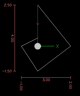
Por ejemplo, si tiene el siguiente programa, puede esperar que sea un patrón cuadrado:
F100 G1 @.5 ^90
G91 @.5 ^90
@.5 ^90
@.5 ^90
@.5 ^90
G90 G0 X0 Y0 M2
You can see from the following figure that the output is not what you might expect. Because we added 0.5 to the distance each time the distance from the XY zero position increased with each line.
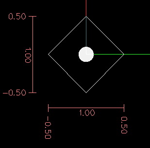
El siguiente código producirá nuestro patrón cuadrado:
F100 G1 @.5 ^90
G91 ^90
^90
^90
^90
G90 G0 X0 Y0 M2
As you can see by only adding to the angle by 90 degrees each time the end point distance is the same for each line.
It is an error if:
-
An incremental move is started at the origin
-
A mix of Polar and X or Y words are used
14. Modal Groups
Los comandos se organizan en conjuntos llamados grupos modales, y solo un miembro de un grupo modal puede estar en vigor en cualquier momento. En general, un grupo modal contiene comandos para los cuales es lógicamente imposible que dos miembros entren en vigencia al mismo tiempo, como medida en pulgadas y medida en milímetros. Un centro de mecanizado puede estar en muchos modos al mismo tiempo, con un modo de cada grupo modal en vigor. Los grupos modales se muestran en la tabla siguiente.
| Modal Group Meaning | Member Words |
|---|---|
Non-modal codes (Group 0) |
G4, G10 G28, G30, G52, G53, G92, G92.1, G92.2, G92.3, |
Motion (Group 1) |
G0, G1, G2, G3, G33, G38.n, G73, G76, G80, G81 G82, G83, G84, G85, G86, G87, G88, G89 |
Plane selection (Group 2) |
G17, G18, G19, G17.1, G18.1, G19.1 |
Modo de distancia (Grupo 3) |
G90, G91 |
Arc IJK Distance Mode (Group 4) |
G90.1, G91.1 |
Feed Rate Mode (Group 5) |
G93, G94, G95 |
Units (Group 6) |
G20, G21 |
Cutter Diameter Compensation (Group 7) |
G40, G41, G42, G41.1, G42.1 |
Tool Length Offset (Group 8) |
G43, G43.1, G49 |
Canned Cycles Return Mode (Group 10) |
G98, G99 |
Coordinate System (Group 12) |
G54, G55, G56, G57, G58, G59, G59.1, G59.2, G59.3 |
Control Mode (Group 13) |
G61, G61.1, G64 |
Spindle Speed Mode (Group 14) |
G96, G97 |
Lathe Diameter Mode (Group 15) |
G7, G8 |
| Modal Group Meaning | Member Words |
|---|---|
Stopping (Group 4) |
M0, M1, M2, M30, M60 |
Pines de E/S (Grupo 5) |
(M62-M65 digital output), (M66 digital or analog input), (M67, M68 analog output) |
Toolchange (Group 6) |
M6 Tn |
Husillo (Grupo 7) |
M3, M4, M5 |
Coolant (Group 8) |
(M7 M8 can both be on), M9 |
Override Switches (Group 9) |
M48, M49 |
User Defined (Group 10) |
M100-M199 |
For several modal groups, when a machining center is ready to accept commands, one member of the group must be in effect. There are default settings for these modal groups. When the machining center is turned on or otherwise re-initialized, the default values are automatically in effect.
El grupo 1, el primero en la tabla, es un grupo de códigos G para movimiento. Uno de ellos siempre está vigente. A ese se le llama modo de movimiento actual.
Es un error colocar un código G del grupo 1 y un código G del grupo 0 en la misma línea si ambos usan palabras de eje. Si un código G del grupo 1 que usa palabras de eje estaba implícitamente vigente en una línea (por haber sido activado en una línea anterior) y un código G del grupo 0 que usa las palabras de eje aparece en la línea, la actividad del código G del grupo 1 es suspendida para esa línea. Los códigos G del grupo 0 que usan palabras de eje son G10, G28, G30, G52 y G92.
It is an error to include any unrelated words on a line with O- flow control.
15. Comentarios
Los comentarios son meramente informativos y no influyen en el comportamiento de la máquina.
Se pueden agregar comentarios a las líneas de código G para ayudar a aclarar la intención del programador. Los comentarios se pueden incrustar en una línea usando paréntesis () o al final de una línea usando un punto y coma. El punto y coma no se trata como el comienzo de un comentario cuando está entre paréntesis.
Comments may appear between words, but not between words and their corresponding parameter. So, S100(set speed)F200(feed) is OK while S(speed)100F(feed) is not.
Here is an example of a commented program:
G0 (Rapid to start) X1 Y1
G0 X1 Y1 (Rapid to start; but don't forget the coolant)
M2 ; End of program.
There are several active comments which look like comments but cause some action, like (debug,..) or (print,..). If there are several comments on a line, only the last comment will be interpreted according to these rules. Hence, a normal comment following an active comment will in effect disable the active comment. For example, (foo) (debug,#1) will print the value of parameter #1, however (debug,#1)(foo) will not.
A comment introduced by a semicolon is by definition the last comment on that line, and will always be interpreted for active comment syntax.
|
Nota
|
Inline comments on O-codes should not be used see the O-code comments section for more information. |
16. Messages
* (MSG,) - displays message if MSG appears after the left parenthesis and before any other printing characters. Variants of MSG which include white space and lower case characters are allowed. The rest of the characters before the right parenthesis are considered to be a message. Messages should be displayed on the message display device of the user interface if provided.
(MSG, This is a message)17. Probe Logging
* (PROBEOPEN filename.txt) - will open filename.txt and store the 9-number coordinate consisting of XYZABCUVW of each successful straight probe in it. * (PROBECLOSE) - will close the open probelog file.
For more information on probing see the G38 section.
18. Logging
* (LOGOPEN,filename.txt) - opens the named log file. If the file already exists, it is truncated. * (LOGAPPEND,filename) - opens the named log file. If the file already exists, the data is appended. * (LOGCLOSE) - closes an open log file. * (LOG,) - everything past the , is written to the log file if it is open. Supports expansion of parameters as described below.
Examples of logging are in nc_files/examples/smartprobe.ngc and in nc_files/ngcgui_lib/rectange_probe.ngc sample G-code files.
19. Abort Messages
* (ABORT,) - displays a message like (MSG,) with the addition of special handling for comment parameters as described below and of aborting the current running process.
20. Debug Messages
* (DEBUG,) - displays a message like (MSG,) with the addition of special handling for comment parameters as described below.
21. Print Messages
* (PRINT,) - messages are output to stderr with special handling for comment parameters as described below.
22. Comment Parameters
In the DEBUG, PRINT and LOG comments, the values of parameters in the message are expanded.
For example: to print a named global variable to stderr (the default console window).
(print,endmill dia = #<_endmill_dia>)
(print,value of variable 123 is: #123)
Inside the above types of comments, sequences like #123 are replaced by the value of the parameter 123. Sequences like #<named parameter> are replaced by the value of the named parameter. Named parameters will have white space removed from them. So, #<named parameter> will be converted to #<namedparameter>.
Parameter numbers can be formatted, e.g.:
(DEBUG, value = %d#<some_value>)will print the value rounded to an integer.
-
%lf is default if there is no formatting string.
-
%d = 0 decimals
-
%f = four decimals
-
%.xf = x (0-9) number of decimals
The formatting will be performed on all parameters in the same line unless changed, i.e., multiple formatting is allowed in one line.
The formatting string does not need to be right beside the parameter.
If the formatting string is created with the wrong pattern it will be printed as characters.
23. File Requirements
A G-code file must contain one or more lines of G-code and be terminated with a Program End. Any G-code past the program end is not evaluated.
Si no se usa un código de finalización de programa, se utilizarán un par de signos de porcentaje % con el primer signo de porcentaje en la primera línea del archivo seguido de una o más líneas de código G y un segundo signo de porcentaje. Cualquier código pasado el segundo signo de porcentaje no es evaluado.
|
Aviso
|
Usar % al principio y final de un archivo de código G no hará lo mismo que usar un Final de Programa. Usando %, la máquina estará en cualquier estado en que el programa la dejó, el husillo y el refrigerante aún pueden estar encendidos y cosas como G90/91 se dejan como el último programa las configuró. Si no usa un preámbulo apropiado, el próximo programa podría comenzar en una condición peligrosa. |
|
Nota
|
The file must be created with a text editor like Gedit and not a word processor like Open Office Word Processor. |
24. File Size
El intérprete y el planificador de tareas están cuidadosamente escritos para que el único límite en el tamaño del programa sea la capacidad del disco. Las interfaces TkLinuxCNC y Axis cargan el texto del programa para mostrarlo al usuario, y entonces la RAM se convierte en un factor limitante. En Axis, donde se dibuja la gráfica de vista previa por defecto, el tiempo de redibujo también se convierte en un límite práctico en el tamaño del programa. La vista previa se puede desactivar en Axis para acelerar la carga de grandes programas. En Axis, las secciones de la vista previa se pueden desactivar usando comentarios de control de vista previa.
25. G-code Order of Execution
The order of execution of items on a line is defined not by the position of each item on the line, but by the following list:
-
O-code commands (optionally followed by a comment but no other words allowed on the same line)
-
Comment (including message)
-
Set feed rate mode (G93, G94).
-
Set feed rate (F).
-
Set spindle speed (S).
-
Select tool (T).
-
HAL pin I/O (M62-M68).
-
Change tool (M6) and Set Tool Number (M61).
-
Spindle on or off (M3, M4, M5).
-
Save State (M70, M73), Restore State (M72), Invalidate State (M71).
-
Coolant on or off (M7, M8, M9).
-
Enable or disable overrides (M48, M49,M50,M51,M52,M53).
-
User-defined Commands (M100-M199).
-
Dwell (G4).
-
Set active plane (G17, G18, G19).
-
Set length units (G20, G21).
-
Cutter radius compensation on or off (G40, G41, G42)
-
Cutter length compensation on or off (G43, G49)
-
Coordinate system selection (G54, G55, G56, G57, G58, G59, G59.1, G59.2, G59.3).
-
Set path control mode (G61, G61.1, G64)
-
Set distance mode (G90, G91).
-
Set retract mode (G98, G99).
-
Go to reference location (G28, G30) or change coordinate system data (G10) or set axis offsets (G52, G92, G92.1, G92.2, G92.3).
-
Perform motion (G0 to G3, G33, G38.n, G73, G76, G80 to G89), as modified (possibly) by G53.
-
Stop (M0, M1, M2, M30, M60).
26. G-code Best Practices
Use at least 3 digits after the decimal when milling in millimeters, and at least 4 digits after the decimal when milling in inches.
In particular, tolerance checks of arcs are done for .001 and .0001 according to the active units.
G-code is most legible when at least one space appears before words. While it is permitted to insert white space in the middle of numbers, there is no reason to do so.
Center-format arcs (which use I- J- K- instead of R- ) behave more consistently than R-format arcs, particularly for included angles near 180 or 360 degrees.
When correct execution of your program depends on modal settings, be sure to set them at the beginning of the part program. Modes can carry over from previous programs and from the MDI commands.
G17 G20 G40 G49 G54 G80 G90 G94
G17 use XY plane, G20 inch mode, G40 cancel diameter compensation, G49 cancel length offset, G54 use coordinate system 1, G80 cancel canned cycles, G90 absolute distance mode, G94 feed/minute mode.
Perhaps the most critical modal setting is the distance units—If you do not include G20 or G21, then different machines will mill the program at different scales. Other settings, such as the return mode in canned cycles may also be important.
Ignore everything in section Order of Execution, and instead write no line of code that is the slightest bit ambiguous.
Don’t use and set a parameter on the same line, even though the semantics are well defined. Updating a variable to a new value, such as #1=[#1+#2] is OK.
Line numbers offer no benefits. When line numbers are reported in error messages, the numbers refer to the line number in the file, not the N-word value.
Considere usar el modo de velocidad de tiempo invertido.
Because the meaning of an F word in meters per minute varies depending on the type of axis to be moved and because the amount of removed material does not depend only on the feed rate, it can be simpler to use G93, inverse speed of time, to achieve the removal of desired material.
27. Linear and Rotary Axis
Because the meaning of an F-word in feed-per-minute mode varies depending on which axes are commanded to move, and because the amount of material removed does not depend only on the feed rate, it may be easier to use G93 inverse time feed mode to achieve the desired material removal rate.
28. Common Error Messages
-
G-code out of range - A G-code greater than G99 was used, the scope of G codes in LinuxCNC is 0 - 99. Not every number between 0 and 99 is a valid G-code.
-
Unknown G-code used - A G-code was used that is not part of the LinuxCNC G-code language.
-
i,j,k word with no Gx to use it - i, j and k words must be used on the same line as the G-code.
-
Cannot use axis values without a G-code that uses them - Axis values can not be used on a line without either a modal G-code in effect or a G-code on the same line.
-
File ended with no percent sign or program end - Every G-code file must end in a M2 or M30 or be wrapped with the percent sign %.