1. Audiencia objetivo
Este documento es una colección de notas sobre los aspectos internos de LinuxCNC. Principalmente de interés para los desarrolladores. Sin embargo, gran parte de la información también puede ser de interés para integradores de sistemas u otros que simplemente estén interesados en el funcionamiento de LinuxCNC. Mucha de esta información está ahora desactualizada y nunca ha sido revisada su exactitud.
2. Organización
Habrá un capítulo para cada uno de los componentes principales de LinuxCNC, así como capítulos que cubren cómo esos componentes trabajan juntos. Este documento es por mucho un trabajo en progreso y su diseño puede cambiar en el futuro.
3. Términos y definiciones
-
EJE: un eje es uno de los nueve grados de libertad que define la posición de una herramienta en el espacio cartesiano tridimensional. Los nueve ejes son referidos como X, Y, Z, A, B, C, U, V y W. Las coordenadas lineales ortogonales X, Y y Z determinan dónde está posicionada la punta de la herramienta. Las coordenadas angulares A, B y C determinan la orientación de la herramienta. Un segundo conjunto de coordenadas lineales ortogonales U, V y W permite el movimiento de la herramienta (generalmente para acciones de corte) en relación con los ejes previamente desplazados y rotados. Lamentablemente, "eje" se usa a veces para significar un grado de libertad de la máquina en sí, como los carros longitudinal y transversal o el avance fino del husillo de una fresadora vertical. En estas maquinas, esto no causa confusión ya que, por ejemplo, el movimiento de la mesa corresponde directamente al movimiento a lo largo del eje X. Sin embargo, las articulaciones de hombro y codo de un brazo robótico y los actuadores lineales de un hexápodo no se corresponde al movimiento a lo largo de ningún eje cartesiano y en general es importante hacer la distinción entre el eje cartesiano y grados de libertad de la máquina. En este documento, esto último se llamarán articulaciones, no ejes. (Las GUI y algunas otras partes de el código no siempre sigue esta distinción, pero las partes internas de el controlador de movimiento si lo hacen.)
-
ARTICULACIÓN: una articulación es cada una de las partes móviles de la máquina. Las articulaciones son distintas de los ejes, aunque los dos términos a veces se usan (incorrectamente) para significa lo mismo. En LinuxCNC, una articulación es un objeto físico que puede ser movido, no una coordenada en el espacio. Por ejemplo, todos los carros, la palanca del husillo o un plato giratorio de una fresadora vertical son articulaciones. El hombro, el codo y la muñeca de un brazo robótico son articulaciones, al igual que los actuadores lineales de un hexápodo. Cada articulación tiene un motor o actuador de algún tipo asociado con ella. Las articulaciones no corresponden necesariamente a los ejes X, Y y Z, aunque para máquinas con cinemática trivial, puede ser el caso. Incluso en esas máquinas, la posición articular y la posición del eje son cosas inherentemente diferentes. En este documento, los términos articulación y eje se utilizan con cuidado para respetar sus distintos significados. Desafortunadamente, eso no es necesariamente cierto en ningún otro lado. En en particular, las GUI para máquinas con cinemática trivial pueden pasar por alto o oculta completamente la distinción entre articulaciones y ejes. Adicionalmente, el archivo INI usa el término eje para datos que serían más precisos describirse como datos de articulaciones, como las escalas de entrada y salida, etc.
|
Nota
|
En la versión 2.8 de LinuxCNC ya se hace esta distinción. El archivo INI cuenta con la nueva sección [JOINT_<núm>]. Muchos de los parámetros que antes eran propios de la sección [AXIS_<letra>] ahora están en la nueva sección. Otras secciones, como [KINS] también adquieren nuevos parámetros para ajustarse a esto. Se ha provisto una secuencia de comandos para transformar archivos INI antiguos a la nueva configuración ejes/articulaciones. |
-
POSE - Una pose es una posición completamente especificada en un espacio cartesiano 3D. En el controlador de movimiento LinuxCNC, cuando nos referimos a una pose nos referimos a una estructura EmcPose, que contiene seis coordenadas lineales (X, Y, Z, U, V y W) y tres angulares (A, B y C).
-
coord, o modo coordinado, significa que todas las articulaciones están sincronizadas y se mueven juntas según lo ordenado por el código de nivel superior. Es el modo normal al mecanizar. En el modo coordinado, se supone que los comandos se dan en el marco de referencia cartesiano, y si la máquina no es cartesiana, los comandos son traducidos por la cinemática para impulsar cada articulación en el espacio articular según sea necesario.
-
free, o modo libre, significa que los comandos se interpretan en el espacio articular. Se usa para mover manualmente (jog) articulaciones individuales, aunque no impide que se muevan múltiples articulaciones a la vez (creo). La detección del punto de inicio de los ejes (homing) también se realiza en modo libre; de hecho, a las máquinas con cinemática no trivial deben tener detectados sus puntos de inicio antes de que puedan pasar al modo coord o teleop.
-
teleop es el modo que probablemente se necesite si se hace trote con un hexápodo. Los comandos de trote implementados por el controlador de movimiento son trotes articulares, que funcionan en modo free. Pero si se desea mover un hexápodo o una máquina similar a lo largo de un eje cartesiano en particular, se debe operar más de una articulación. Para eso está teleop.
4. Descripción general de la arquitectura
Hay cuatro componentes contenidos en la Arquitectura LinuxCNC: un controlador de movimiento (EMCMOT), un controlador de E/S discreto (EMCIO), un ejecutor de tareas que los coordina (EMCTASK) y varias interfaces de usuario en modo texto y gráfico. Cada uno de ellos se describirá en el presente documento, tanto desde el punto de vista del diseño como del punto de vista de los desarrolladores (dónde encontrar los datos necesarios, cómo ampliar/modificar cosas fácilmente, etc.).
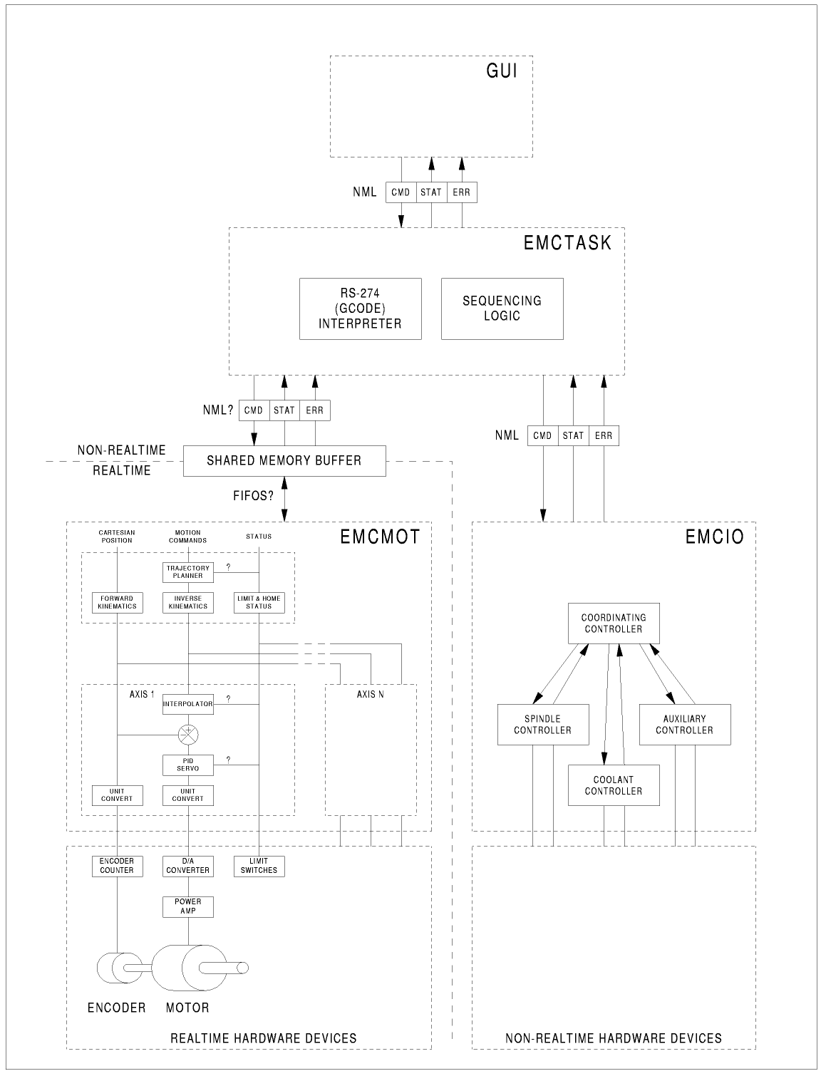
4.1. Arquitectura del software LinuxCNC
Al nivel más general, LinuxCNC es un jerarquía de tres controladores: el manejador de comandos a nivel de tarea e intérprete de programa, el controlador de movimiento y el controlador de E/S discretas. El controlador de E/S discretas está implementado como una jerarquía de controladores, en este caso para husillo, refrigerante y subsistemas auxiliares (p. ej., Estop). El controlador de tareas coordina las acciones de los controladores de movimiento y de E/S discretas. Sus acciones están programadas en programas convencionales de control numérico "código G y M", que son interpretados por el controlador de tareas en mensajes NML y enviados al movimiento.
5. Introducción al controlador de movimiento
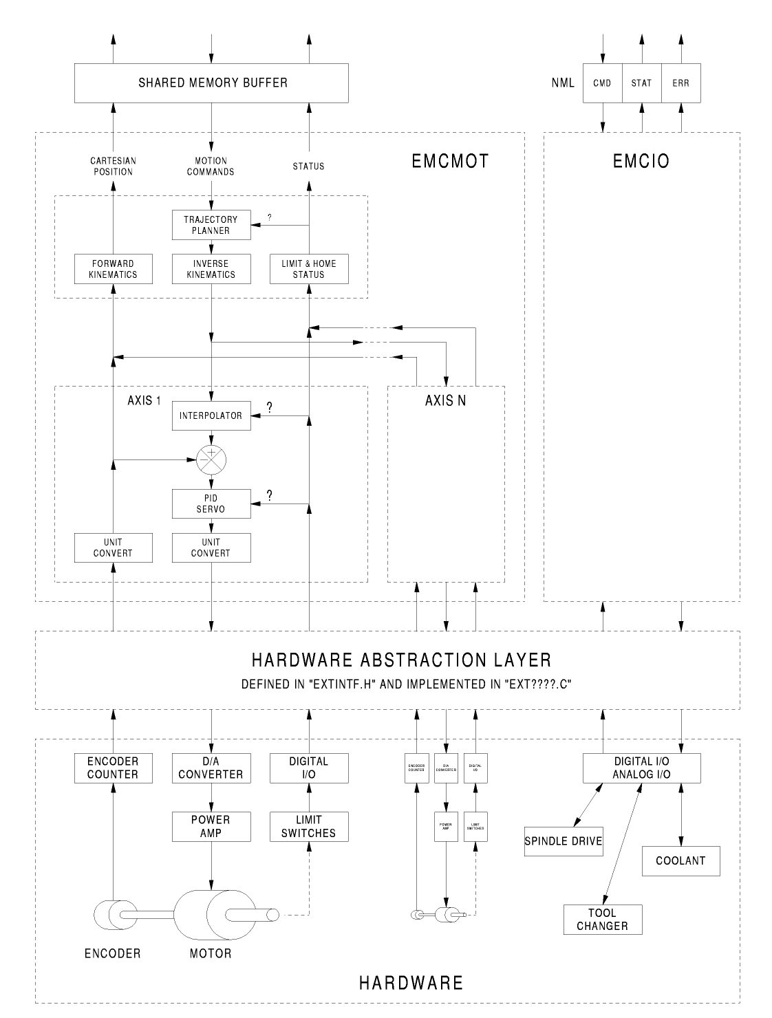
El controlador de movimiento es un componente de tiempo real. Recibe los comandos de control de movimiento desde las partes en tiempo no-real de LinuxCNC (p. ej. el intérprete de código G/Task, GUIs, etc.) y ejecuta esos comandos dentro de un contexto de tiempo real. La comunicación desde el contexto en tiempo no-real hacia el contexto en tiempo real ocurre mediante un mecanismo IPC pasa-mensajes que usa memoria compartida, y vía la Capa de abstracción de hardware (HAL).
El estado del controlador de movimiento esta disponible para el resto de LinuxCNC mediante el mismo IPC pasa-mensajes en memoria compartida y a través de HAL.
El controlador de movimiento interactúa con los controladores de motor y otro hardware en tiempo real y no-real usando HAL.
Este documento asume que el lector tiene una comprensión básica de HAL, y comprende términos como pines HAL, señales HAL, etc., por lo que no se explican. Para obtener más información sobre HAL, consulte el Manual HAL. Otro capítulo de este documento entrará eventualmente en las interioridades del propio HAL, pero en este capítulo, solo usamos la API HAL, definida en src/hal/hal.h.
5.1. Módulos del controlador de movimiento
La funciones de tiempo real del controlador de movimiento están implementadas con módulos de tiempo real — objetos compartidos en espacio de usuario para sistemas Preempt-RT o módulos de kernel para algunas implementaciones de tiempo real en modo kernel como RTAI:
-
tpmod - planificación de trayectoria
-
homemod - funciones homing
-
motmod - procesa comandos NML y controla hardware vía HAL
-
kinematics module - realiza cinemáticas directas (articulaciones->coordenadas) e inversas (coordenadas->articulaciones)
LinuxCNC se inicia con una secuencia de comandos linuxcnc que lee un archivo de configuración INI e inicia todos los procesos necesarios. Para control de movimiento en tiempo real, la secuencia de comandos primero carga los módulos predeterminados tpmod y homemod y luego carga los módulos de cinemáticas y movimiento de acuerdo con las configuraciones de los archivos HAL especificados en el archivo INI.
En vez de usar los módulos predeterminados, se pueden usar módulos personalizados (compilados por el usuario) de homing o planificación de trayectoria mediante configuraciones en archivo INI u opciones de línea de comandos. Los módulos personalizados deben implementar todas las funciones usadas por los módulos predeterminados. La utilería halcompile puede crear módulos personalizados.
6. Diagrama de bloques y flujo de datos
La siguiente figura es un diagrama de bloques de un controlador articular. Hay un controlador por articulación. Los controladores articulares funcionan a un nivel más bajo que la cinemática; un nivel donde todas las articulaciones son completamente independientes. Todos los datos para una articulación está en una sola estructura articular. Algunos miembros de esa estructura son visible en el diagrama de bloques, como coarse_pos, pos_cmd y motor_pos_fb.
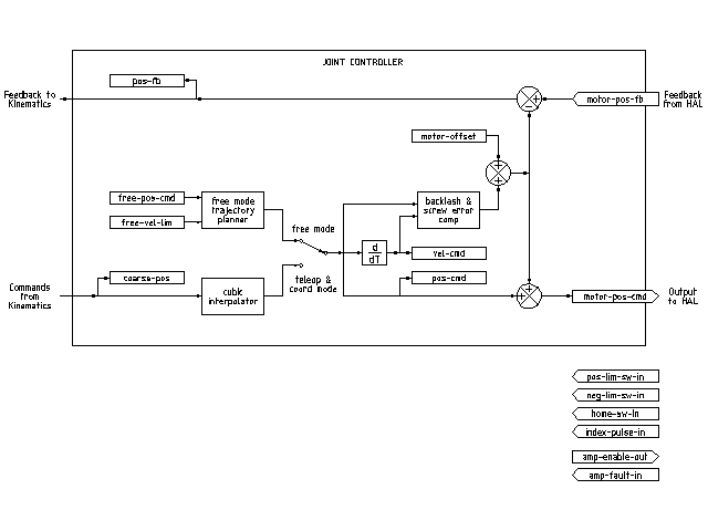
La figura anterior muestra cinco de los siete conjuntos de información de posición que forman el flujo principal de datos a través del controlador de movimiento. Las siete formas de datos de posición son las siguientes:
-
emcmotStatus->carte_pos_cmd - Esta es la posición deseada, en coordenadas cartesianas. Se actualiza a tasa traj, no a tasa servo. En modo coord, se determina por el planificador traj. En modo teleop, está determinado por el planificador traj?. En modo libre, es copiado de actualPos, o generado mediante la aplicación de cinemática directa a (2) o (3).
-
emcmotStatus->joints[n].coarse_pos - Esta es la posición deseada, en coordenadas articulares, pero antes de interpolación. Se actualiza a tasa traj, no a tasa servo. En modo coord, se genera aplicando cinematica inversa a (1). En modo teleop, se genera aplicando cinemática inversa a (1). En modo libre, creo que se copia de (3).
-
emcmotStatus->joints[n].pos_cmd - Esta es la posición deseada, en coordenadas articulares, después de interpolación. En cada período servo se genera un nuevo conjunto de estas coordenadas. En modo coord se genera a partir de (2) por el interpolador. En modo teleop, se genera a partir de (2) por el interpolador. En modo free es generado por el planificador de trayectoria de modo libre.
-
emcmotStatus->joints[n].motor_pos_cmd - Esta es la posición deseada, en coordenadas de motor. Las coordenadas del motor se generan agregando compensación de holgura mecánica, compensación de error del tornillo de avance y offset (para homing) a (3). Se genera de la misma manera independientemente del modo, y es la salida al bucle PID u otro bucle de posición.
-
emcmotStatus->joints[n].motor_pos_fb - Esta es la posición real, en coordenadas de motor. Es la entrada de codificadores u otro dispositivo de retroalimentación (o desde codificadores virtuales en máquinas de bucle abierto). Es "generado" por la lectura del dispositivo de retroalimentación.
-
emcmotStatus->joints[n].pos_fb - Esta es la posición real en coordenadas articulares. Se genera restando offsets, compensación de error del tornillo de avance y compensación de holgura mecánica de (5). Se genera de la misma manera, independientemente del modo operativo.
-
emcmotStatus->carte_pos_fb - Esta es la posición real, en coordenadas cartesianas. Se actualiza a tasa traj, no a tasa servo. Idealmente, actualPos siempre se calcularía aplicando cinemática directa a (6). Sin embargo, la cinemática directa puede no estar disponible, o pueden ser inutilizable porque uno o más ejes no están en casa. En ese caso, las opciones son: A) fingirla, copiando (1), o B) admitir que realmente no se conocen las coordenadas cartesianas, y simplemente no actualizar actualPos. Cualquiera que sea el enfoque utilizado, no veo ninguna razón para no hacerlo de la misma manera, independientemente del modo de operación. Yo propondría lo siguiente: si hay cinemática directa, usarla, a menos que no funcionen debido a ejes no-en casa u otros problemas, en cuyo caso hacer (B). Si no hay cinemática directa, hacer (A), ya que de lo contrario actualPos nunca estará actualizada.
7. Homing
7.1. Diagrama de estado de homing

7.2. Otro diagrama de homing

8. Comandos
Los comandos se implementan mediante una gran instrucción switch en la función emcmotCommandHandler(), que se llama a la tasa servo. Más sobre esa función más adelante.
Hay aproximadamente 44 comandos - esta lista todavía está en construcción.
|
Nota
|
La enumeración cmd_code_t, en motion.h, contiene 73 comandos, pero la instrucción switch en command.c contempla sólo 70 comandos (hasta 5/jun/2020). Los comandos ENABLE_WATCHDOG / DISABLE_WATCHDOG están en motion-logger.c. Quizás estén obsoletos. El comando SET_TELEOP_VECTOR solo aparece en motion-logger.c, sin más efecto que su propio log. |
8.1. ABORT
El comando ABORT simplemente detiene todo movimiento. Se puede emitir en cualquier momento y siempre será aceptado. No deshabilita el controlador de movimiento ni cambia ninguna información de estado; simplemente cancela cualquier movimiento que esté actualmente en progreso. Nota al pie:[Parece que el código de nivel superior (TASK y superior) también usa ABORT para borrar fallos. Siempre que haya un fallo persistente (como estar fuera de interruptores hardware de límite), el código de nivel superior envía un flujo constante de ABORTs al controlador de movimiento en su intento de sobrepasar el fallo. Miles de ellos … Eso significa que el controlador de movimiento debe evitar fallos persistentes. Esto necesita ser investigado.]
8.1.1. Requisitos
Ninguno. El comando siempre se acepta y actúa inmediatamente.
8.1.2. Resultados
En modo libre, los planificadores de trayectoria de modo libre quedan deshabilitados. Esto da como resultado que cada articulación se detenga tan rápido como su límite de aceleración (desaceleración) permita. La parada no está coordinada. En modo teleop, la velocidad cartesiana comandada se establece a cero. No sé exactamente qué tipo de parada resulta (coordinada, descoordinada, etc.), pero lo resolveré finalmente. En modo coord, se le dice al planificador de trayectoria del modo coord que aborte el movimiento actual. De nuevo, no sé el resultado exacto de esto, pero lo documentaré cuando lo resuelva.
8.2. FREE
El comando FREE pone el controlador de movimiento en modo libre. Modo libre significa que cada articulación es independiente de todas las demás articulaciones. Coordenadas cartesianas, poses y cinemáticas se ignoran cuando está en modo libre. En esencia, cada articulación tiene su propio planificador de trayectoria simple, y cada articulación ignora por completo las otras articulaciones. Algunos comandos (como JOG y HOME de articulación) solo funcionan en modo libre. Otros comandos, incluso cualquier cosa que trate con coordenadas cartesianas, no funciona en absoluto en modo libre.
8.2.1. Requisitos
El controlador de comandos no aplica requisitos al comando FREE, siempre será aceptado. Sin embargo, si alguna articulación está en movimiento (GET_MOTION_INPOS_FLAG () == FALSE), entonces el comando será ignorado. Este comportamiento está controlado por un código que ahora se encuentra en la función set_operating_mode() en control.c, ese código debe limpiarse. Creo que el comando no debe ignorarse en silencio, sino que el controlador de comandos debe determinar si se puede ejecutar y devolver un error si no puede.
8.2.2. Resultados
Si la máquina ya está en modo libre, nada. De lo contrario, la máquina se coloca en modo libre. Cada planificador de trayectoria en modo libre de articulación se inicializa con la ubicación actual de la articulación, pero los planificadores no están habilitados y las articulaciones están estacionadas.
8.3. TELEOP
El comando TELEOP coloca la máquina en modo de teleoperación. En teleop modo, el movimiento de la máquina se basa en coordenadas cartesianas utilizando cinemática, en lugar de en articulaciones individuales como en modo libre. Sin embargo, el planificador de trayectoria per se no se usa, en cambio el movimiento es controlado por un vector de velocidad. El movimiento en modo teleop es muy parecido a trotar, excepto que se hace en espacio cartesiano en lugar de espacio de articulación. En una máquina con cinemática trivial, hay pequeña diferencia entre el modo teleop y el modo libre, y las GUI para esas máquinas podrían ni siquiera emitir este comando. Sin embargo, para máquinas no triviales como robots y hexápodos, el modo teleop se utiliza para la mayoría de los movimientos tipo jog ordenados por usuario.
8.3.1. Requisitos
El controlador de comandos rechazará el comando TELEOP con un error mensaje si la cinemática no se puede activar porque una o más articulaciones no han sido dirigidas. Además, si alguna articulación está en movimiento (GET_MOTION_INPOS_FLAG () == FALSE), entonces el comando será ignorado (sin mensaje de error). Este comportamiento está controlado por un código que ahora esta ubicado en la función set_operating_mode() en control.c. Creo que el comando no debe ser ignorado en silencio, sino el controlador del comando debe determinar si se puede ejecutar y devolver un error si no puede.
8.3.2. Resultados
Si la máquina ya está en modo teleop, nada. De lo contrario la máquina se coloca en modo teleop. El código cinemático está activado, los interpoladores son drenados y enjuagados, y los comandos de velocidad cartesiana se ponen a cero.
8.4. COORD
El comando COORD coloca la máquina en modo coordinado. En modo coord, el movimiento de la máquina se basa en coordenadas cartesianas utilizando cinemáticas, en lugar de articulaciones individuales como en modo libre. Además, el planificador de trayectoria principal se utiliza para generar movimiento, con base en comandos LINE, CIRCLE y/o PROBE en cola. El modo coord es el modo que se usa al ejecutar un programa de código G.
8.4.1. Requisitos
El controlador de comandos rechazará el comando COORD con un error mensaje si la cinemática no se puede activar porque una o más articulaciones no han sido dirigidas. Además, si alguna articulación está en movimiento (GET_MOTION_INPOS_FLAG () == FALSE), entonces el comando será ignorado (sin mensaje de error). Este comportamiento está controlado por un código que ahora esta ubicado en la función set_operating_mode() en control.c. Creo que el comando no debe ser ignorado en silencio, sino que el controlador de comando debe determinar si se puede ejecutar y devolver un error si no puede.
8.4.2. Resultados
Si la máquina ya está en modo coord, nada. De lo contrario, la máquina se coloca en modo coord. El código cinemático está activado, los interpoladores son drenados y enjuagados, y las colas de planificador de trayectoria son vaciadas. El planificador de trayectoria está activo y en espera de un comando LINE, CIRCLE o PROBE.
8.5. ENABLE
El comando ENABLE habilita el controlador de movimiento.
8.5.1. Requisitos
Ninguna. El comando puede emitirse en cualquier momento y siempre será aceptado.
8.5.2. Resultados
Si el controlador ya está habilitado, nada. Si no, el controlador es habilitado. Las colas y los interpoladores se drenan. Cualquier movimiento u operación de homing se finaliza. Las salidas amp-enable asociadas con articulaciones activas se encienden. Si no hay cinemática directa disponible, la máquina se cambia al modo libre.
8.6. DISABLE
El comando DISABLE deshabilita el controlador de movimiento.
8.6.1. Requisitos
Ninguna. El comando puede emitirse en cualquier momento y siempre será aceptado.
8.6.2. Resultados
Si el controlador ya está deshabilitado, nada. Si no, el controlador está desactivado. Las colas y los interpoladores se drenan. Cualquier movimiento u operación de homing se finaliza. Las salidas amp-enable asociadas con las articulaciones activas son apagadas. Si no hay cinemática directa disponible, la máquina se cambia al modo libre.
8.7. ENABLE_AMPLIFIER
El comando ENABLE_AMPLIFIER activa la salida de habilitación del amplificador para un amplificador de salida única, sin cambiar nada más. Puede ser usado para habilitar un controlador de velocidad del husillo.
8.7.1. Requisitos
Ninguna. El comando puede emitirse en cualquier momento y siempre será aceptado.
8.7.2. Resultados
Actualmente nada. (Una llamada a la antigua función extAmpEnable esta actualmente comentada). Eventualmente establecerá el pin HAL de habilitación del amplificador a TRUE.
8.8. DISABLE_AMPLIFIER
El comando DISABLE_AMPLIFIER apaga la salida de habilitación del amplificador para un solo amplificador, sin cambiar nada más. De nuevo, útil para controladores de velocidad del husillo.
8.8.1. Requisitos
Ninguna. El comando puede emitirse en cualquier momento y siempre será aceptado.
8.8.2. Resultados
Actualmente nada. (Una llamada a la antigua función extAmpEnable está actualmente comentada). Eventualmente establecerá el pin HAL de habilitación del amplificador en FALSE.
8.9. ACTIVATE_JOINT
El comando ACTIVATE_JOINT activa todos los cálculos asociados con una sola articulación, pero no cambia el pin de salida de habilitación del amplificador de la articulación.
8.9.1. Requisitos
Ninguna. El comando puede emitirse en cualquier momento y siempre será aceptado.
8.9.2. Resultados
Los cálculos para la articulación especificada están habilitados. El pin de habilitación del amplificador no se cambia, sin embargo, cualquier comando ENABLE o DISABLE posterior modificará el pin de habilitación del amplificador de la articulación.
8.10. DEACTIVATE_JOINT
El comando DEACTIVATE_JOINT desactiva todos los cálculos asociados con una sola articulación, pero no cambia la salida del pin de habilitación del amplificador de la articulación.
8.10.1. Requisitos
Ninguna. El comando puede emitirse en cualquier momento y siempre será aceptado.
8.10.2. Resultados
Los cálculos para la articulación especificada están habilitados. El pin de habilitación del amplificador no se cambia, y los comandos ENABLE o DISABLE subsecuentes no modificarán el pin de habilitación del amplificador de la articulación.
8.11. ENABLE_WATCHDOG
El comando ENABLE_WATCHDOG habilita un perro guardián basado en hardware (si está presente).
8.11.1. Requisitos
Ninguna. El comando puede emitirse en cualquier momento y siempre será aceptado.
8.11.2. Resultados
Actualmente nada. El antiguo watchdog era una cosa extraña que utilizaba una tarjeta de sonido específica. Es posible que en el futuro se diseñe una nueva interfaz de watchdog.
8.12. DISABLE_WATCHDOG
El comando DISABLE_WATCHDOG deshabilita un perro guardián basado en hardware (si está presente).
8.12.1. Requisitos
Ninguna. El comando puede emitirse en cualquier momento y siempre será aceptado.
8.12.2. Resultados
Actualmente nada. El antiguo watchdog era una cosa extraña que utilizaba una tarjeta de sonido específica. Es posible que en el futuro se diseñe una nueva interfaz de watchdog.
8.13. PAUSE
El comando PAUSE detiene el planificador de trayectoria. No tiene efecto en modo libre o teleop. En este punto no sé si detiene todo el movimiento inmediatamente, o si completa el movimiento actual y luego se detiene antes de jalar otro movimiento de la cola.
8.13.1. Requisitos
Ninguna. El comando puede emitirse en cualquier momento y siempre será aceptado.
8.13.2. Resultados
El planificador de trayectoria hace una pausa.
8.14. RESUME
El comando RESUME reinicia el planificador de trayectoria si está en pausa. No tiene efecto en modo libre o teleop, o si el planificador no está en pausa.
8.14.1. Requisitos
Ninguna. El comando puede emitirse en cualquier momento y siempre será aceptado.
8.14.2. Resultados
Se reanuda el planificador de trayectoria.
8.15. STEP
El comando STEP reinicia el planificador de trayectoria si está en pausa, y le dice al planificador que se detenga nuevamente cuando llegue a un punto específico. No tiene efecto en modo libre o teleop. En este punto no se exactamente cómo funciona esto. Agregaré más documentación aquí cuando excave más profundo en el planificador de trayectoria.
8.15.1. Requisitos
Ninguna. El comando puede emitirse en cualquier momento y siempre será aceptado.
8.15.2. Resultados
El planificador de trayectoria se reanuda y luego se detiene cuando llega a un punto específico.
8.16. SCALE
El comando SCALE escala todos los límites de velocidad y comandos por una cantidad especificada. Se utiliza para implementar la anulación de velocidad de alimentación y otros funciones similares. El escalado funciona en modo libre, teleop y coord, y afecta todo, incluidas las velocidades de homing, etc. Sin embargo, los límites individuales de velocidad de articulación no se ven afectados.
8.16.1. Requisitos
Ninguna. El comando puede emitirse en cualquier momento y siempre será aceptado.
8.16.2. Resultados
Todos los comandos de velocidad son escalados por la constante especificada.
8.17. OVERRIDE_LIMITS
El comando OVERRIDE_LIMITS evita que los límites se disparen hasta el fin del siguiente comando JOG. Normalmente se usa para permitir que una máquina salga de un interruptor de límite después de disparar. (El comando puede usarse en realidad para anular límites o para cancelar una anulación anterior.)
8.17.1. Requisitos
Ninguna. El comando puede emitirse en cualquier momento y siempre será aceptado. (Creo que solo debería funcionar en modo libre.)
8.17.2. Resultados
Los límites en todas las articulaciones se anulan hasta el final del próximo comando JOG. (Esto está roto actualmente … una vez que se recibe un comando OVERRIDE_LIMITS, los límites se ignoran hasta que otro comando OVERRIDE_LIMITS los vuelve a habilitar.)
8.18. HOME
El comando HOME inicia una secuencia de homing en una articulación especificada. La secuencia homing real está determinada por unos parámetros de configuración, y puede variar desde simplemente establecer la posición actual a cero, hasta una búsqueda en varias etapas de un interruptor de casa y pulso de índice, seguido de un movimiento a una ubicación de casa arbitraria. Para más información sobre la secuencia de homing consultar el Manual del integrador.
8.18.1. Requisitos
El comando se ignorará en silencio a menos que la máquina esté en modo libre.
8.18.2. Resultados
Se anula cualquier trote o movimiento de articulación y se inicia la secuencia de homing.
8.19. JOG_CONT
El comando JOG_CONT inicia un trote continuo en una sola articulación. Se genera un trote continuo al establecer la posición objetivo del planificador de trayectoria en modo libre a un punto más allá del final del rango de carrera de la articulación. Esto asegura que el planificador moverá constantemente hasta que sea detenido por los límites de articulación o por un comando ABORT. Normalmente, una GUI envía un comando JOG_CONT cuando el usuario presiona un botón de trote, y un ABORT al soltar el botón.
8.19.1. Requisitos
El controlador de comandos rechazará el comando JOG_CONT con un mensaje de error si la máquina no está en modo libre, o si alguna articulación está en movimiento (GET_MOTION_INPOS_FLAG () == FALSE), o si el movimiento no está habilitado. También ignorará silenciosamente el comando si la articulación ya está en (o más allá de) su límite y el trote ordenado lo empeoraría.
8.19.2. Resultados
El planificador de trayectoria de modo libre para la articulación identificada por emcmotCommand->eje es activado, con una posición destino más allá del final de carrera de la articulación, y un límite de velocidad de emcmotCommand->vel. Este comienza el movimiento de la articulación, y el movimiento continuará hasta ser detenido por un comando ABORT o al alcanzar un límite. El planificador de modo libre acelera al límite de aceleración de articulación al comienzo del movimiento, y desacelerará al límite de aceleración de articulación cuando se detenga.
8.20. JOG_INCR
El comando JOG_INCR inicia un trote gradual en una sola articulación. Los trotes incrementales son acumulativos, en otras palabras, emitir dos comandos JOG_INCR pidiendo cada uno 0.100 pulgadas de movimiento resultarán en 0.200 pulgadas de recorrido, incluso si el segundo comando se emite antes que termine el primero. Normalmente, los trotes incrementales se detienen cuando ya recorrieron la distancia deseada, sin embargo, también se detienen cuando topan con un límite, o con un comando ABORT.
8.20.1. Requisitos
El controlador de comandos rechazará silenciosamente el comando JOG_INCR si la máquina no está en modo libre, o si alguna articulación está en movimiento (GET_MOTION_INPOS_FLAG () == FALSE), o si el movimiento no está habilitado. También ignorará silenciosamente el comando si la articulación ya está en (o más allá de) su límite y el trote ordenado lo empeoraría.
8.20.2. Resultados
El planificador de trayectoria de modo libre para la articulación identificada por emcmotCommand->eje está activado, la posición destino es incrementada/decrementada por emcmotCommand->offset, y el límite de velocidad se establece en emcmotCommand->vel. El planificador de trayectoria de modo libre generará un movimiento trapezoidal suave desde la posición actual hasta la posición destino. El planificador puede manejar correctamente los cambios en posición objetivo que ocurran mientras el movimiento este en progreso, por lo que se pueden emitir múltiples comandos JOG_INCR en sucesión rápida. El planificador de modo libre acelera al límite de aceleración de articulación al comienzo del movimiento, y desacelerará al límite de aceleración de articulación para detenerse en el posición destino.
8.21. JOG_ABS
El comando JOG_ABS inicia un trote absoluto en una sola articulación. Un trote absoluto es un simple movimiento a una ubicación específica en coordenadas articulares. Normalmente los trotes absolutos se detienen cuando alcanzan la ubicación deseada, sin embargo, también se detienen cuando alcanzan un límite, o con un comando ABORT.
8.21.1. Requisitos
El controlador de comandos rechazará silenciosamente el comando JOG_ABS si la máquina no está en modo libre, o si alguna articulación está en movimiento (GET_MOTION_INPOS_FLAG () == FALSE), o si el movimiento no está habilitado. También ignorará silenciosamente el comando si la articulación ya está en (o más allá de) su límite y el trote ordenado lo empeoraría.
8.21.2. Resultados
El planificador de trayectoria de modo libre para la articulación identificada por emcmotCommand->axis está activado, la posición destino se establece a emcmotCommand->offset, y el límite de velocidad se establece a emcmotCommand->vel. El planificador de trayectoria de modo libre generará un movimiento trapezoidal suave desde la posición actual hasta la posición destino. El planificador puede manejar correctamente los cambios a la posición destino que sucedan mientras el movimiento está en progreso. Si varios comandos JOG_ABS se emiten en sucesión rápida, cada nuevo comando cambia la posición destino y la máquina pasa a la posición final ordenada. El planificador de modo libre acelera al límite de aceleración de articulación en el comienzo del movimiento, y desacelerará al límite de aceleración de articulación para detenerse en la posición destino.
8.22. SET_LINE
El comando SET_LINE agrega una línea recta a la cola del planificador de trayectoria.
(Más tarde)
8.23. SET_CIRCLE
El comando SET_CIRCLE agrega un movimiento circular a la cola del planificador de trayectoria.
(Más tarde)
8.24. SET_TELEOP_VECTOR
El comando SET_TELEOP_VECTOR indica al controlador de movimiento que se mueva a lo largo de un vector específico en el espacio cartesiano.
(Más tarde)
8.25. PROBE
El comando PROBE indica al controlador de movimiento que se mueva hacia un punto específico en el espacio cartesiano, deteniendo y grabando su posición si se dispara la entrada de la sonda.
(Más tarde)
8.26. CLEAR_PROBE_FLAG
El comando CLEAR_PROBE_FLAG se usa para restablecer la entrada de la sonda en preparación para un comando PROBE. (Pregunta: ¿por qué el comando PROBE no debería restablecer automáticamente la entrada?)
(Más tarde)
8.27. SET_xix
Hay aproximadamente 15 comandos SET_xxx, donde xxx es el nombre de algún parámetro de configuración. Se anticipa que habrá varios comandos SET más a medida que se agregan más parámetros. Me gustaría encontrar una forma más limpia de establecer y leer los parámetros de configuración. Los métodos existentes requieren que se agreguen muchas líneas de código a múltiples archivos cada vez que se agrega un parámetro. Gran parte de ese código es idéntico o casi idéntico para cada parámetro.
9. Compensación de error de tornillo y holgura mecánica
FIXME Compensación de holguras y errores de tornillos
10. Controlador de tareas (EMCTASK)
10.1. Estado
Task tiene tres estados internos posibles: E-stop, E-stop Reset, y Machine on.

11. Controlador E/S (EMCIO)
El controlador de E/S es parte de TASK. Interactúa con E/S externas usando pines HAL.
Actualmente ESTOP/Enable, el refrigerante, y el cambio de herramienta se manejan con iocontrol. Estos son eventos de velocidad relativamente baja; las E/S coordinadas de alta velocidad se manejan en motion.
emctaskmain.cc envía comandos de E/S mediante taskclass.cc.
Proceso del bucle principal de iocontrol:
-
comprueba si las entradas HAL han cambiado
-
comprueba si read_tool_inputs() indica que el cambio de herramienta ha finalizado y establece emcioStatus.status
12. Interfaces de usuario
Interfaces de usuario FIXME
13. Introducción a libnml
libnml se deriva de rcslib del NIST sin todo el soporte multi-plataformas. Muchas de las envolturas de código específico de plataforma han sido eliminadas, junto con gran parte del código que no es requerido por LinuxCNC. Se espera que quede suficiente compatibilidad con rcslib para que las aplicaciones puedan implementarse en plataformas que no sean Linux y aún ser capaz de comunicarse con LinuxCNC.
Este capítulo no pretende ser una guía definitiva para usar libnml (o rcslib); en cambio proporcionará eventualmente una visión general de cada clase C++ y sus funciones miembro. Inicialmente, la mayoría de estas notas se agregarán como comentarios aleatorios a medida que el código se analice y modifique.
14. LinkedList
Clase base para mantener una lista enlazada. Este es uno de los principales bloques de construcción utilizados para pasar mensajes NML y una variedad de estructuras de datos internas.
15. LinkedListNode
Clase base para producir una lista enlazada. Su propósito es mantener punteros a los nodos anteriores y siguientes, puntero a los datos y el tamaño de los datos.
No asigna memoria para el almacenamiento de datos.
16. SharedMemory
Proporciona un bloque de memoria compartida junto con un semáforo (heredado de la clase Semaphore). La creación y destrucción del semáforo es manejado por el constructor y destructor SharedMemory.
17. ShmBuffer
Clase para pasar mensajes NML entre procesos locales mediante memoria intermedia de uso compartido. Gran parte del funcionamiento interno se hereda de la clase CMS.
18. Timer
La clase Timer proporciona un temporizador periódico limitado solo por la resolución del reloj del sistema. Si, por ejemplo, un proceso necesita ser ejecutado cada 5 segundos, independientemente del tiempo que lleve ejecutar el proceso, el siguiente fragmento de código muestra cómo hacerlo:
main()
{
    timer = new Timer(5.0);    /* Inicializa un temporizador con un ciclo de 5 segundos */
    while(0) {
        /* Hacer algún proceso */
        timer.wait();    /* Espera hasta el siguiente intervalo de 5 segundos */
    }
    delete timer;
}
19. Semaphore
La clase Semaphore proporciona un método de exclusiones mutuas para acceder a un recurso compartido. La función para obtener un semáforo puede bloquear hasta que el acceso esté disponible, regresar después de un tiempo de espera o regresar inmediatamente con o sin obtener el semáforo. El constructor creará un semáforo o adjuntará a uno existente si la ID ya está en uso.
Semaphore::destroy() debe ser invocado solo por el último proceso.
20. CMS
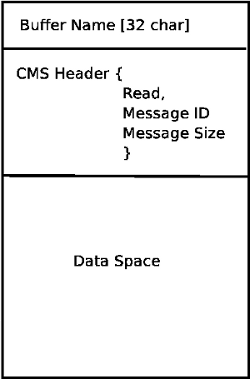
En el corazón de libnml está la clase CMS. Contiene la mayor parte de las funciones utilizadas por libnml y finalmente NML. Muchas de las funciones internas se sobrecargan para permitir métodos de paso de datos dependientes de hardware específico. Al final, todo gira en torno a un bloque central de memoria (denominado "búfer de mensajes" o simplemente búfer). Este búfer puede existir como un bloque de memoria compartida accedido por otros procesos CMS/NML, o un búfer local y privado para la transmisión de datos por red o interfaces seriales.
El búfer se asigna dinámicamente en tiempo de ejecución para permitir una mayor flexibilidad del subsistema CMS/NML. El tamaño del búfer debe ser suficientemente grande para acomodar el mensaje más grande, una pequeña cantidad para uso interno y permitir que el mensaje se codifique si se elige esta opción (los datos codificados se cubrirán más adelante). La figura siguiente es una vista interna del espacio del búfer.
La clase base de CMS es la principal responsable de crear las vías de comunicación e interfazar con el sistema operativo.
21. Formato del archivo de configuración
La configuración NML consta de dos tipos de formatos de línea. Uno para búfers y un segundo para procesos que se conectan a los búfers.
21.1. Línea de búfer
El formato NIST original de la línea de búfer es:
-
B nombre tipo host tamaño neut RPC# búfer# máx_procs clave [configuraciones específicas por tipo]
-
B- identifica la línea como una configuración de búfer.
-
nombre- es el identificador del búfer.
-
tipo- describe el tipo de búfer: SHMEM, LOCMEM, FILEMEM, PHANTOM o GLOBMEM.
-
host- es una dirección IP o un nombre de host para el servidor NML
-
tamaño- es el tamaño del búfer
-
neut- un booleano para indicar si los datos en el búfer están codificados en un formato independiente de la máquina, o sin formato.
-
RPC#- obsoleto - marcador de posición retenido solo para compatibilidad con versiones anteriores.
-
búfer#- un número identificador único que se usa si un servidor controla varios búfers.
-
máx_procs- número máximo de procesos permitidos para conectarse a este búfer.
-
clave - es un identificador numérico para un búfer de memoria compartida
21.2. Configuraciones específicas por tipo
El tipo de búfer implica opciones de configuración adicionales mientras que el sistema operativo anfitrión impide ciertas combinaciones. En una tentativa de concretar la documentación publicada en un formato coherente, solo será cubierto el tipo de buffer SHMEM.
-
mutex=os_sem- modo predeterminado para proporcionar el semáforo de bloqueo de la memoria intermedia.
-
mutex=none- no utilizado
-
mutex=no_interrupts - no aplicable en un sistema Linux
-
mutex=no_switching - no aplicable en un sistema Linux
-
mutex=mao split- divide el búfer en la mitad (o más) y permite que un proceso acceda a una parte del búfer mientras que un segundo proceso está escribiendo en la otra parte.
-
TCP=(número de puerto)- especifica qué puerto de red utilizar.
-
UDP =(número de puerto) - ídem
-
STCP =(número de puerto) - ídem
-
serialPortDevName=(puerto serie) - sin documentar.
-
passwd=file_name.pwd- agrega una capa de seguridad al búfer requiriendo que cada proceso proporcione una contraseña.
-
bsem- la documentación del NIST implica una clave para un semáforo de bloqueo, y si bsem=-1, se evitan los bloqueos de lectura.
-
queue- permite pasar mensajes en cola.
-
ascii - Codifica mensajes en formato de texto plano
-
disp- codifica los mensajes en un formato adecuado para mostrarlos (???)
-
xdr- codifica mensajes en Representación de Datos Externos. (Ver rpc/xdr.h para más detalles).
-
diag- habilita almacenado de diagnósticos en el búfer (¿temporizaciones y recuentos de bytes?)
21.3. Línea de proceso
El formato NIST original de la línea de proceso es:
P nombre búfer tipo host ops servidor tiempo master c_num [configuraciones específicas por tipo]
-
P- identifica esta línea como una configuración de proceso.
-
nombre- es el identificador del proceso.
-
búfer - es uno de los búfers definidos en otra parte del archivo de configuración.
-
tipo- define si este proceso es local o remoto en relación con el búfer.
-
host- especifica en qué parte de la red se está ejecutando este proceso.
-
ops- proporciona al proceso acceso de solo lectura, solo escritura o de lectura/escritura al búfer.
-
servidor- especifica si este proceso ejecutará un servidor para este búfer.
-
tiempo - establece las características de tiempo de espera para los accesos al búfer.
-
master - indica si este proceso es responsable de crear y destruir el búfer.
-
c_num - un número entero entre cero y (máx_procs -1)
21.4. Comentarios de configuración
Algunas de las combinaciones de configuración no son válidas, mientras que otras implican ciertas restricciones. En un sistema Linux GLOBMEM es obsoleto, mientras que PHANTOM solo es realmente útil en la etapa de prueba de una aplicación; igualmente para FILEMEM. LOCMEM es de poca utilidad para una aplicación multiproceso, y solo ofrece ventajas limitadas de rendimiento sobre SHMEM. Esto deja a SHMEM como el único tipo de búfer para usar con LinuxCNC.
La opción neut solo se usa en un sistema multiprocesador donde arquitecturas diferentes (e incompatibles) comparten un bloque de memoria. La probabilidad de ver un sistema de este tipo fuera de un museo o lugar de investigación es remoto y solo es relevante para buffers GLOBMEM.
El número RPC está documentado como obsoleto y solo se conserva por razones de compatibilidad.
Con un nombre de búfer único, tener una identidad numérica parece ser inútil. Es necesario revisar el código para identificar la lógica. Asimismo, el campo clave parece ser redundante, y podría derivarse del nombre del búfer.
El propósito de limitar el número de procesos permitidos para conectarse a cualquier búfer no está claro a partir de la documentación existente y del código fuente original. Permitir un número no especificado de procesos para conectarse a un búfer no es más difícil de implementar.
Los tipos mutex se reducen a uno de estos dos; el predeterminado "os_sem" o "mao split". La mayoría de los mensajes NML son relativamente cortos y se pueden copiar hacia o desde el búfer con retrasos mínimos, por lo que las lecturas divididas no son esenciales.
La codificación de datos solo es relevante cuando se transmite a un proceso remoto - Usar TCP o UDP implica codificación XDR. La codificación ASCII puede tener algún uso en diagnósticos o para pasar datos a un sistema integrado que no implementa NML.
Los protocolos UDP tienen menos verificaciones en los datos y permiten descartar un porcentaje de paquetes. TCP es más confiable, pero es relativamente más lento.
Si LinuxCNC se va a conectar a una red, se esperaría que sea local y detrás de un cortafuegos. La única razón para permitir el acceso a LinuxCNC a través de internet sería para diagnósticos remotos. Esto puede lograrse de manera mucho más segura utilizando otros medios, tal vez por una interfaz web.
El comportamiento exacto cuando el tiempo de espera se establece en cero o un valor negativo no está claro desde los documentos del NIST. Solo se mencionan valores INF y positivos. Sin embargo, enterrado en el código fuente de rcslib, parece aplicar lo siguiente:
- tiempo > 0
-
Bloqueo de acceso hasta que se alcanza el intervalo de tiempo de espera o el acceso al búfer esté disponible.
- tiempo = 0
-
El acceso al búfer solo es posible si no hay otro proceso que esté leyendo o escribiendo en ese momento.
- tiempo < 0 o INF
-
El acceso está bloqueado hasta que el búfer esté disponible.
22. Clase base NML
Expande las listas y la relación entre NML, NMLmsg y las clases cms de nivel inferior.
No debe confundirse con NMLmsg, RCS_STAT_MSG o RCS_CMD_MSG.
NML es responsable de analizar el archivo de configuración, configurar los búfers cms y es el mecanismo para enrutar mensajes al(los) búfer(s) correcto(s). Para hacer esto, NML crea varias listas para:
-
búferes cms creados o conectados.
-
procesos y búferes a las que se conectan
-
una larga lista de funciones de formato para cada tipo de mensaje
Este último elemento es probablemente el núcleo de gran parte de la desalineación de libnml/rcslib y NML en general. Cada mensaje que se pasa a través de NML requiere que se adjunte una cierta cantidad de información además de los datos reales. Para hacer esto, se invocan en secuencia varias funciones de formato para ensamblar fragmentos del mensaje general. Las funciones de formato incluirán NML_TYPE, MSG_TYPE, además de los datos declarados en clases NMLmsg derivadas. Los cambios en el orden en que se llaman las funciones de formato y también las variables pasadas pueden romper la compatibilidad con rcslib si se hacen mal. Hay razones para mantener la compatibilidad con rcslib y buenas razones para alterar el código. La pregunta es ¿qué conjunto de razones son primordiales?
22.1. Interioridades de NML
22.1.1. Constructor NML
NML::NML() analiza el archivo de configuración y lo almacena en una lista enlazada para ser pasada a constructores cms en líneas simples. Es la función del constructor NML para llamar al constructor cms relevante para cada búfer y mantener una lista de los objetos cms y los procesos asociados con cada búfer.
NML puede interactuar con cms desde los punteros almacenados en las listas y es por esto que Doxygen no muestra las relaciones reales involucradas.
|
Nota
|
La configuración se almacena en la memoria antes de pasar un puntero a una línea específica para el constructor cms. El constructor cms analiza luego la línea nuevamente para extraer un par de variables … Tendría más sentido hacer TODO el análisis y guardar las variables en una estructura que sea pasada al constructor cms. Esto eliminaría la manipulación de cadenas y reduciría el código duplicado en cms … |
22.1.2. Lectura/escritura NML
Las llamadas a NML::read y NML::write realizan tareas similares en el modo de procesar el mensaje; la única variación real está en el dirección del flujo de datos.
Una llamada a la función de lectura primero obtiene datos del búfer y luego llama a format_output(), mientras que una función de escritura llamaría a format_input() antes de pasar los datos al búfer. Dentro de format_xxx() se realiza el trabajo de construir o deconstruir el mensaje. Una lista de funciones variadas se llama a su vez para colocar varias partes del encabezado NML (que no debe confundirse con el encabezado cms) en el orden correcto - La última función llamada es emcFormat() en emc.cc.
22.1.3. Relaciones NMLmsg y NML
NMLmsg es la clase base de la que se derivan todas las clases de mensajes. Cada clase de mensaje debe tener un ID único definido (y pasado al constructor) y también una función update(*cms). update() será llamado por las funciones de lectura/escritura NML cuando se llama al formateador NML - El puntero al formateador habrá sido declarado en el constructor NML en algún momento. En virtud de las listas enlazadas que crea NML, puede seleccionar el puntero cms que se pasa al formateador y, por tanto, que búfer se utilizará.
23. Agregar comandos NML personalizados
LinuxCNC es bastante impresionante, pero algunas partes necesitan algunos ajustes. Como ya sabe, la comunicación se realiza a través de canales NML. Los datos enviados a través de tales canales es una de las clases definidas en emc.hh (implementado en emc.cc). Si alguien necesita un tipo de mensaje que no existe, debería seguir estos pasos para agregar uno nuevo. (El mensaje que se agrega en el ejemplo se llama EMC_IO_GENERIC (hereda EMC_IO_CMD_MSG (hereda RCS_CMD_MSG)))
-
agregar la definición de la clase EMC_IO_GENERIC a emc2/src/emc/nml_intf/emc.hh
-
agregar la definición de tipo: #define EMC_IO_GENERIC_TYPE \((NMLTYPE) 1605)
-
(Se elige 1605 porque esta disponible) en emc2/src/emc/nml_intf/emc.hh
-
-
agregar el caso EMC_IO_GENERIC_TYPE a emcFormat en emc2/src/emc/nml_intf/emc.cc
-
agregar el caso EMC_IO_GENERIC_TYPE a emc_symbol_lookup en emc2/src/emc/nml_intf/emc.cc
-
agregar la función EMC_IO_GENERIC::update a emc2/src/emc/nml_intf/emc.cc
Al recompilar, el nuevo mensaje debería estar allí. La siguiente parte es enviar tales mensajes desde algún lugar y recibirlos en otro lugar, y hacer algunas cosas con eso.
24. La tabla de herramientas y el cambiador de herramientas
LinuxCNC interactúa con el hardware del cambiador de herramientas y tiene una abstracción interna del mismo. LinuxCNC gestiona la información de la herramienta en un archivo de tabla de herramientas.
24.1. Abstracción del cambiador de herramientas en LinuxCNC
LinuxCNC admite dos tipos de hardware de cambiador de herramientas, llamados no-aleatorio y aleatorio. La configuración INI [EMCIO]RANDOM_TOOLCHANGER controla cuál de estos tipos de hardware considera LinuxCNC que está conectado.
24.1.1. Cambiadores de herramientas no aleatorios
El hardware de cambiador de herramientas no aleatorio vuelve a colocar cada herramienta en la ranura desde la que fue originalmente cargada.
Ejemplos de hardware de cambiador de herramientas no aleatorio son el cambiador de herramientas "manual", torretas de herramientas de torno y cambiadores de herramientas en rack.
Cuando se configura para un cambiador de herramientas no aleatorio, LinuxCNC no cambia el número de ranura en el archivo de la tabla de herramientas a medida que las herramientas se cargan y descargan. Internamente, en el cambio de herramienta la información de la herramienta se copia de la ranura fuente de la tabla de herramientas a la ranura 0 (que representa el husillo), reemplazando cualquier información de herramienta que estaba allí anteriormente.
|
Nota
|
Con LinuxCNC configurado para cambiador de herramientas no aleatorio, la herramienta 0 (T0) tiene significado especial: "sin herramienta". T0 puede no aparecer en el archivo de tabla de herramientas y cambiar a T0 dará como resultado que LinuxCNC piense que tiene el husillo vacío. |
24.1.2. Cambiadores de herramientas aleatorios
El hardware de cambiador de herramientas aleatorio intercambia la herramienta en el husillo (si existe) con la herramienta solicitada a cambiar. Así, la ranura donde reside una herramienta cambia a medida que se intercambia dentro y fuera del husillo.
Un ejemplo de hardware de cambiador de herramientas aleatorio es un cambiador de herramientas de carrusel.
Cuando se configura para un cambiador de herramientas aleatorio, LinuxCNC intercambia el número de ranura de la herramienta antigua y la nueva en el archivo de tabla de herramientas cuando se cargan las herramientas. Internamente, en el cambio de herramienta la información de la herramienta se intercambia entre la ranura de origen de la tabla de herramientas y la ranura 0 (que representa el husillo). Por tanto, después de un cambio de herramienta, la ranura 0 en la tabla de herramientas tendrá la información de la herramienta para la nueva herramienta y la ranura de la que la nueva herramienta vino tendrá la información de la herramienta que estaba en el husillo antes del cambio de herramienta, si la había.
|
Nota
|
En LinuxCNC configurado para cambiador de herramientas aleatorio, la herramienta 0 (T0) no tiene significado especial. Se trata exactamente como cualquier otra herramienta en la tabla de herramientas. Es habitual utilizar T0 para representar "sin herramienta" (es decir, una herramienta con TLO cero), de modo que el husillo se pueda vaciar convenientemente cuando sea necesario. |
24.2. La tabla de herramientas
LinuxCNC realiza un seguimiento de las herramientas en un archivo llamado << sec:tool-table,tabla de herramientas>>. La tabla de herramientas registra la siguiente información para cada herramienta:
- número de herramienta
-
Un entero que identifica de forma exclusiva esta herramienta. Los números de herramienta son manejados de manera diferente por LinuxCNC cuando se configuran cambiadores de herramientas no aleatorios o aleatorios:
-
Cuando LinuxCNC está configurado para un cambiador de herramientas no aleatorio, el número debe ser positivo. T0 recibe un manejo especial y no está permitido que aparezca en la tabla de herramientas.
-
Cuando LinuxCNC está configurado para un cambiador de herramientas aleatorio este número debe ser positivo o cero. T0 está permitido en la tabla de herramientas y generalmente se usa para representar "ninguna herramienta", es decir, ranura vacía.
-
- número de ranura
-
Un entero que identifica la cavidad o ranura en el hardware del cambiador donde reside la herramienta. Los números de ranura se manejan de manera diferente por LinuxCNC cuando está configurado para cambiadores de herramientas aleatorios y no aleatorio:
-
Cuando LinuxCNC está configurado para un cambiador de herramientas no aleatorio, el número de ranura en el archivo de herramientas puede ser cualquier número entero positivo (ranura 0 no está permitida). LinuxCNC compacta en silencio los números de ranura cuando carga el archivo de herramienta, por lo que puede haber una diferencia entre los números de ranura en el archivo de herramientas y los números internos de ranura utilizados por LinuxCNC con cambiador de herramienta no aleatorio.
-
Cuando LinuxCNC está configurado para un cambiador de herramientas aleatorio, los números de ranura en el archivo de herramientas deben estar entre 0 y 1000, inclusivamente. Las ranuras 1-1000 están en el cambiador de herramientas; la ranura 0 es el husillo.
-
- diámetro
-
Diámetro de la herramienta, en unidades de máquina.
- offsets de longitud de herramienta
-
Offset de longitud de herramienta (también llamado TLO), hasta en 9 ejes, en unidades máquina. Los ejes que no tienen un TLO especificado, quedan con 0.
24.3. Códigos G que afectan a las herramientas
Los códigos G que usan o afectan la información de la herramienta son:
24.3.1. Txxx
Le dice al hardware del cambiador de herramientas que se prepare para cambiar a una determinada herramienta xxx.
Manejado por Interp::convert_tool_select().
-
Se le pide a la máquina que se prepare para cambiar a la herramienta seleccionada llamando a la función
SELECT_TOOL()de Canon con el número de la herramienta solicitada.-
(saicanon) No-op.
-
(emccanon) Crea un mensaje
EMC_TOOL_PREPAREcon el número de ranura solicitada y lo envía a Task, que lo envía a IO. IO recibe el mensaje y le pide a HAL que prepare la ranura configurandoiocontrol.0.tool-prep-pocket,iocontrol.0.tool-prep-number, yiocontrol.0.tool-prepare. IO luego llama repetidamente aread_tool_inputs()para sondear el pin HALiocontrol.0.tool-prepared, el cual señaliza a IO desde el hardware del cambiador de herramientas, a través de HAL, que la preparación de la herramienta solicitada está completa. Cuando ese pin se vuelve true, IO estableceemcioStatus.tool.pocketPreppedcon el número de ranura de la herramienta solicitada.
-
-
De vuelta a interp, se le asigna a
settings->selected_pocketel índice de datos de la herramienta solicitada xxx.
|
Nota
|
Los nombres heredados selected_pocket y current_pocket en realidad hacen referencia a un índice secuencial de datos de herramientas para elementos de herramientas cargados desde una tabla de herramientas ([EMCIO]TOOL_TABLE) o a través de una base de datos de herramientas ([EMCIO]DB_PROGRAM). |
24.3.2. M6
Le dice al cambiador de herramientas que cambie a la herramienta seleccionada actualmente (seleccionada por el comando Txxx anterior).
Manejado por Interp::convert_tool_change().
-
Se le pide a la máquina que cambie a la herramienta seleccionada llamando a la función
CHANGE_TOOL()de Canon consettings->selected_pocket(un índice de datos de herramienta).-
(saicanon) Establece el
_active_slotde sai en el número de ranura pasado. La información de la herramienta se copia de la ranura seleccionada de la tabla de herramientas (es decir, desde_tools[_active_slot]de sai) al husillo (también conocido como el_tools[0]de sai). -
(emccanon) Envía un mensaje
EMC_TOOL_LOADa Task, que lo envía a IO. IO estableceemcioStatus.tool.toolInSpindleal número de herramienta de la herramienta en el ranura identificada poremcioStatus.tool.pocketPrepped(establecido porTxxxaliasSELECT_POCKET()). Luego solicita que el hardware cambiador de herramientas realice un cambio de herramienta, estableciendo el pin HALiocontrol.0.tool-changea True. Más tarde,read_tool_inputs()de IO detectará que el pin HALiocontrol.0.tool_changedse ha establecido en True, lo que indica que el cambiador de herramienta ha completado el cambio de herramienta. Cuando esto pasa, llama aload_tool()para actualizar el estado de la máquina.-
load_tool()con un cambiador de herramientas no aleatorio, copia la información de la herramienta de la ranura seleccionada al husillo (ranura 0). -
load_tool()con un cambiador de herramientas aleatorio, intercambia la información de herramienta entre la ranura 0 (el husillo) y la ranura seleccionada, luego guarda la tabla de herramientas.
-
-
-
De vuelta en interp, a
settings->current_pocketse le asigna el nuevo índice de datos de herramienta desdesettings->selected_pocket(establecido porTxxx). Los parámetros numerados relevantes (#5400- #5413) son actualizados con la nueva información de herramienta de la ranura 0 (husillo).
24.3.3. G43/G43.1/G49
Aplica offset de longitud de herramienta. G43 usa el TLO de la herramienta cargada actualmente, o de una herramienta especificada si la palabra H se da en el bloque. G43.1 consigue el TLO de las palabras de eje en el bloque. G49 cancela el TLO (usa 0 para el offset de todos los ejes).
Manejado por Interp::convert_tool_length_offset().
-
Comienza construyendo una
EmcPoseque contiene los offsets de 9 ejes a usar. ParaG43.1, estos offsets de herramienta provienen de palabras de eje en el bloque actual. ParaG43estos offsets provienen de la herramienta actual (la herramienta en la ranura 0), o de la herramienta especificada por la palabra H en el bloque. Para G49, los offsets son todos 0. -
Los offsets se pasan a la función
USE_TOOL_LENGTH_OFFSET()de Canon.-
(saicanon) Graba el TLO en
_tool_offset. -
(emccanon) Crea un mensaje
EMC_TRAJ_SET_OFFSETque contiene los offsets y lo envía a Task, que copia los offsets enemcStatus->task.toolOffsety los envía a Motion a través de un comandoEMCMOT_SET_OFFSET. Motion copia los offsets aemcmotStatus->tool_offset, donde se usa para compensar movimientos futuros.
-
-
De vuelta en interp, los offsets se registran en
settings->tool_offset. La ranura efectiva se registra ensettings->tool_offset_index, aunque este valor nunca se usa.
24.3.4. G10 L1/L10/L11
Modifica la tabla de herramientas.
Manejado por Interp::convert_setup_tool().
-
Selecciona el número de herramienta de la palabra P en el bloque y encuentra la ranura para esa herramienta:
-
Con una configuración de cambiador de herramientas no aleatorio, este es siempre el número de ranura en el cambiador de herramientas (incluso cuando la herramienta está en el husillo).
-
Con una configuración de cambiador de herramientas aleatorio, si la herramienta está actualmente cargada utiliza la ranura 0 (ranura 0 significa "el husillo"), y si la herramienta no está cargada, usa el número de ranura en el cambiador de herramientas. (Esta diferencia es importante.)
-
-
Averigua cuáles deberían ser los nuevos offsets.
-
La nueva información de la herramienta (diámetro, offsets, ángulos y orientación), junto con el número de herramienta y el número de ranura, se pasan a la llamada de Canon SET_TOOL_TABLE_ENTRY().
-
(saicanon) Copia la información de la nueva herramienta en el ranura especificada (en la tabla de herramientas interna de sai, + _tools +).
-
(emccanon) Crea un mensaje + EMC_TOOL_SET_OFFSET + con la información de la nueva herramienta y la envía a Task, quien la pasa a IO. IO actualiza la ranura especificada en su copia interna de la tabla de herramientas (
emcioStatus.tool.toolTable), y si la herramienta especificada está cargada actualmente (se compara conemcioStatus.tool.toolInSpindle) entonces la información de la nueva herramienta se copia también en el ranura 0 (el husillo). (FIXME: eso es un buglet, solo debería copiarse en máquinas no aleatorias). Finalmente IO guarda la nueva tabla de herramientas.
-
-
De vuelta en interp, si la herramienta modificada está cargada actualmente en el husillo, y si la máquina es un cambiador de herramientas no aleatorio, entonces la nueva información de herramienta se copia de la ranura de inicio de la herramienta a la ranura 0 (el husillo) en la copia de interp de la tabla de herramientas,
settings->tool_table. (Esta copia no es necesaria con un cambiador aleatorio, porque allí, las herramientas no tienen un ranura inicial y en su lugar, solo actualizamos directamente la herramienta en la ranura 0). Los parámetros numerados relevantes (#5400-#5413) se actualizan con la información de la herramienta en el husillo (copiando la información en interp desettings->tool_tableasettings->parameters). (FIXME: esto es un buglet, los parámetros sólo deberían actualizarse si la herramienta actual fue la modificada). -
Si la herramienta modificada está cargada actualmente en el husillo, y si la configuración es para un cambiador de herramientas no aleatorio, entonces el la nueva información de herramienta también se escribe en el ranura 0 de la tabla de herramientas, a través de una segunda llamada a SET_TOOL_TABLE_ENTRY(). (Esta segunda actualización a la tabla de herramientas no es necesaria con cambiadores aleatorios porque allí, las herramientas no tienen un ranura casa y en su lugar solo actualizamos directamente la herramienta en la ranura 0.)
24.3.5. M61
Establece el número de herramienta actual. Esto cambia la representación interna de LinuxCNC de cuál herramienta está en el husillo, sin mover realmente el cambiador de herramientas o intercambiar alguna herramienta.
Manejado por Interp::convert_tool_change().
Canon: CHANGE_TOOL_NUMBER ()
A settings->current_pocket se le asigna el índice de datos de la herramienta actual especificado por el argumento palabra Q.
24.3.6. G41/G41.1/G42/G42.1
Habilita la compensación del radio del cortador (normalmente llamado compensación de cortador).
Manejado por Interp::convert_cutter_compensation_on().
No hay llamada de Canon, la compensación del cortador ocurre en el intérprete. Usa la tabla de herramientas de la manera esperada: si se proporciona un número de herramienta palabra D busca el número de ranura del número de herramienta especificado en la tabla, y si no se proporciona ninguna palabra D utiliza la ranura 0 (el husillo).
24.3.7. G40
Cancela la compensación del radio de corte.
Manejado por Interp::convert_cutter_compensation_off().
No hay llamada de Canon, la compensación del cortador ocurre en el intérprete. No se usa la tabla de herramientas.
24.4. Variables de estado interno
¡Esta no es una lista exhaustiva! La información de las herramienta esta esparcida por todo LinuxCNC.
24.4.1. IO
emcioStatus es de tipo EMC_IO_STAT
- emcioStatus.tool.pocketPrepped
-
Cuando IO recibe la señal de HAL de que la preparación del cambiador de herramientas ha terminado (después de un comando
Txxx), esta variable se establece en la ranura de la herramienta solicitada. Cuando IO recibe la señal de HAL que el cambio de herramienta en sí ha terminado (después de un comandoM6) esta variable se restablece a -1. - emcioStatus.tool.toolInSpindle
-
Número de la herramienta instalada actualmente en el husillo. Exportada en el pin HAL
iocontrol.0.tool-number(s32). - emcioStatus.tool.toolTable[]
-
Una arreglo de estructuras
CANON_TOOL_TABLE,CANON_POCKETS_MAXlong. Cargada desde el archivo de la tabla de herramientas al inicio y mantenida ahí después. El índice 0 es el husillo, los índices 1- (CANON_POCKETS_MAX-1) son las ranuras en el cambiador de herramientas. Esta es una copia completa de la información de las herramientas, mantenida por separado de lasettings.tool_tablede Interp.
24.4.2. interp
settings es de tipo settings, definida como struct setup_struct en src/emc/rs274ngc/interp_internal.hh.
- settings.selected_pocket
-
Índice de datos de la herramienta seleccionada más recientemente por
Txxx. - settings.current_pocket
-
Índice original de datos de la herramienta actualmente en el husillo. En otras palabras: de cuál índice de datos de herramienta se cargó la herramienta actual en el husillo.
- settings.tool_table[]
-
Un arreglo de información de herramientas. El índice en el arreglo es el "número de cavidad" (también conocido como "número de ranura"). La cavidad 0 es el husillo, las cavidades 1 hasta (CANON_POCKETS_MAX-1) son las cavidades del cambiador de herramientas.
- settings.tool_offset_index
-
No usado. FIXME: Probablemente debería eliminarse.
- settings.toolchange_flag
-
Interp establece esto en verdadero cuando llama a la función CHANGE_TOOL() de Canon. Se verifica en
Interp::convert_tool_length_offset()para decidir qué índice de datos de herramienta usar para G43 (sin palabra H):settings->current_pocketsi el cambio de herramienta aún está en progreso, índice de datos de herramienta 0 (el husillo) si se terminó el cambio de herramienta. - settings.random_toolchanger
-
Establecida desde la variable INI
[EMCIO]RANDOM_TOOLCHANGERal inicio. Controla varias lógicas de manejo de la tabla de herramientas. (IO también lee esta variable INI y cambia su comportamiento con base en ella. Por ejemplo, al guardar la tabla de herramientas, para un cambiador aleatorio guarda la herramienta en el husillo (ranura 0), pero un cambiador no aleatorio guarda cada herramienta en su "ranura casa".) - settings.tool_offset
-
Esta es una variable
EmcPose.-
Se utiliza para calcular la posición en varios lugares.
-
Enviada a Motion a través del mensaje
EMCMOT_SET_OFFSET. Todo lo que hace Motion con los offsets es exportarlos a los pines HALmotion.0.tooloffset.[xyzabcuvw]. FIXME: exportarlos desde algún lugar más cercano a la tabla de herramientas (io o interp, probablemente) y eliminar el mensaje EMCMOT_SET_OFFSET.
-
- settings.pockets_max
-
Se usa de manera intercambiable con
CANON_POCKETS_MAX(una constante #defined, establecida en 1000 a partir de abril de 2020). FIXME: Esta variable de configuración actualmente no es útil y probablemente debería eliminarse. - settings.tool_table
-
Esta es un arreglo de estructuras
CANON_TOOL_TABLE(definidas ensrc/emc/nml_intf/emctool.h), con entradasCANON_POCKETS_MAX. Indexado por "número de cavidad", también conocido como "número de ranura". El índice 0 es el husillo, los índices 1 a (CANON_POCKETS_MAX-1) son las ranuras en el cambiador de herramientas. En un cambiador aleatorio, los números de ranura son significativos. En un cambiador no aleatorio, los ranuras no tienen significado; los números de ranura en el archivo de la tabla de herramientas se ignoran y a las herramientas se les asignan ranuras detool_tablesecuencialmente. - settings.tool_change_at_g30
- settings.tool_change_quill_up
- settings.tool_change_with_spindle_on
-
Estas se establecen a partir de variables INI en la sección
[EMCIO], y determinan cómo se realizan los cambios de herramienta.
25. Recuento de articulaciones y ejes
25.1. En el búfer de estado
El búfer de estado es utilizado por Task y las UIs.
FIXME: axis_mask y axes sobre-especifican el número de ejes
-
status.motion.traj.axis_mask -
Una máscara de bits con un "1" para los ejes que están presentes y un "0" para los ejes que no están presentes. X es el bit 0 con valor 20 = 1 si esta prendido, Y es el bit 1 con valor 21= 2, Z es bit 2 con valor 4, etc. Por ejemplo, una máquina con ejes X y Z tendría una
axis_maskde 0x5, una máquina XYZ tendría 0x7, y una máquina XYZB tendría unaaxis_maskde 0x17. -
status.motion.traj.axes(eliminada) -
Este valor fue eliminado en LinuxCNC versión 2.9. Usar en su lugar
axis_mask. -
status.motion.traj.joints -
Un conteo del número de articulaciones que tiene la máquina. Un torno normal tiene 2 articulaciones, una manejando el eje X y otra manejando el eje Z. Una fresadora de pórtico XYYZ tiene 4 articulaciones, una manejando X, una manejando un lado de la Y, una manejando el otro lado de la Y, y una manejando Z. Una fresadora XYZA también tiene 4 articulaciones.
-
status.motion.axis[EMCMOT_MAX_AXIS] -
Una arreglo de
EMCMOT_MAX_AXISestructuras de eje .axis[n]es válido si(axis_mask & (1 << n))es verdadero. Si(axis_mask & (1 << n))es falso, entoncesaxis [n]no existe en esta máquina y debe ser ignorado. -
status.motion.joint[EMCMOT_MAX_JOINTS] -
Una arreglo de
EMCMOT_MAX_JOINTSestructuras de articulación. Dejoint[0]ajoint[articulaciones-1]son válidas, las otras no existen en esta máquina y deben ser ignoradas.
Las cosas ya no son así actualmente en la rama joints-axes, pero desviaciones de este diseño se consideran errores. Como ejemplo de tal error, ver el tratamiento a los ejes en src/emc/ini/initraj.cc: loadTraj (). Indudablemente hay más, y necesito tu ayuda para encontrarlos y arreglarlos.
25.2. En Motion
El componente en tiempo real controlador de movimiento Motion obtiene primero el número de articulaciones del parámetro de tiempo de carga num_joints. Esto determina cuántas articulaciones valen para crear pines HAL al inicio.
El número de articulaciones de Motion se puede cambiar en tiempo de ejecución utilizando el comando EMCMOT_SET_NUM_JOINTS desde Task.
El controlador Motion siempre funciona en los ejes EMCMOT_MAX_AXIS. Siempre crea nueve conjuntos de pines axis.*.*.