1. How LinuxCNC Works
When you start LinuxCNC from the CNC menu or by typing linuxcnc in the terminal the LinuxCNC script starts the Configuration Selector. When you pick a configuration LinuxCNC reads the INI file then loads the HAL files in the order that they are listed in the INI file.
When you create a configuration with the Stepper Configuration Wizard or Mesa Hardware Wizard or by picking a sample configuration from the Configuration Selector LinuxCNC creates some directories and files in your user directory. In the following example the name of the configuration is My Lathe.
-
linuxcnc
-
configs
-
My_Lathe
-
My_Lathe.ini (this is read by the linuxcnc script)
-
My_Lathe.hal (this hal file is loaded before the gui)
-
post_gui.hal (this hal file is loaded after the gui)
-
linuxcnc.var (stores the parameters)
-
linuxcnc.var.bak (a backup parameter file)
-
tool.tbl (the tool table file)
-
-
-
nc_files
-
*.ngc (G code files)
-
-
There can be other directorys and files in a configuration but the above is usually the minimum files used.
LinuxCNC can control machine tools, robots, or other automated devices. It can control servo motors, stepper motors, relays, and other devices related to motion control. LinuxCNC can control up to 9 axes in coordinated motion.
There are five main components to the LinuxCNC software:
-
a motion controller (EMCMOT)
-
a discrete I/O controller (EMCIO)
-
a task executor which coordinates them (EMCTASK)
-
a graphical user interface.
-
a hardware abstraction layer (HAL)
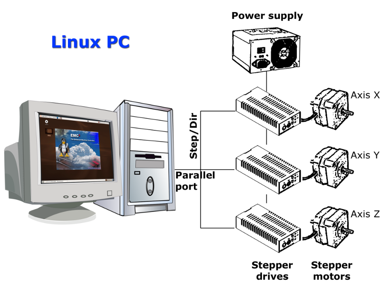
The above figure shows a simple block diagram showing what a typical 3-axis LinuxCNC system might look like. This diagram shows a stepper motor system. The PC, running Linux as its operating system, is actually controlling the stepper motor drives by sending signals through the printer port. These signals (pulses) make the stepper drives move the stepper motors. The LinuxCNC system can also run servo motors via servo interface cards or by using an extended parallel port to connect with external control boards. As we examine each of the components that make up an LinuxCNC system we will remind the reader of this typical machine.
2. Graphical User Interfaces
A user interface is the part of the LinuxCNC that the machine tool operator interacts with. The LinuxCNC comes with several types of user interfaces:
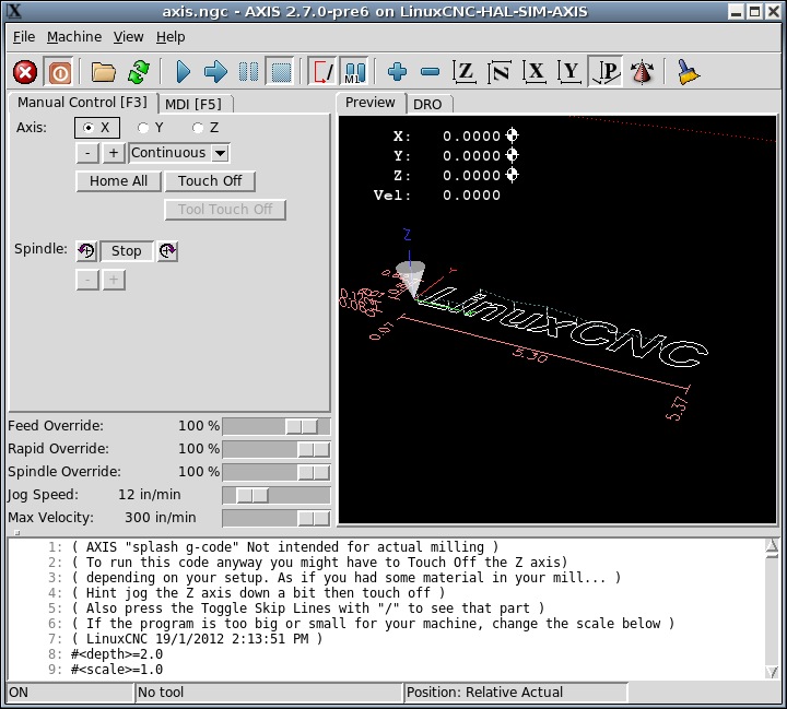
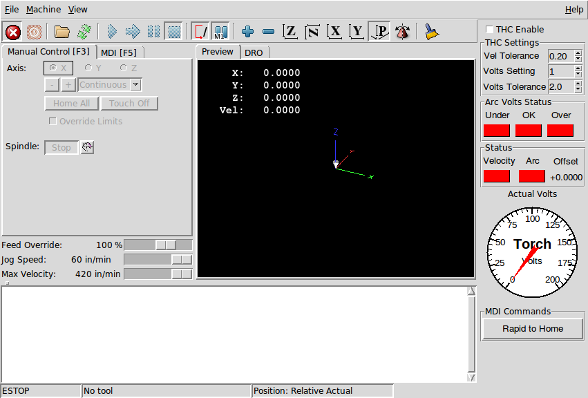
Axis, the standard keyboard GUI interface.
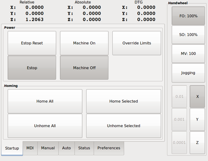
Touchy, a touch screen GUI.
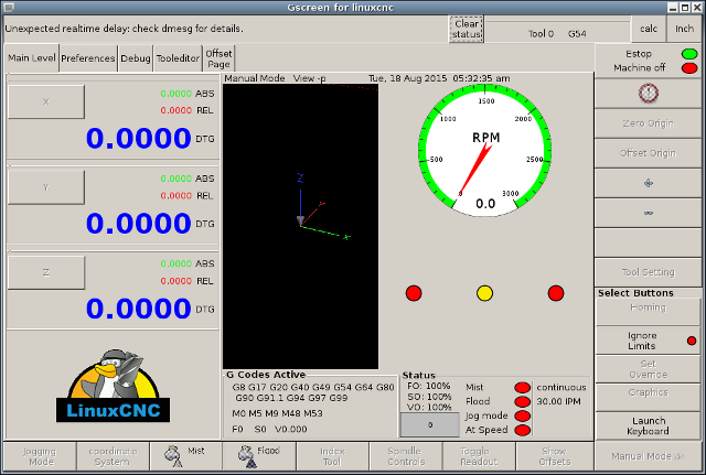
Gscreen, a configurable base touch screen GUI.
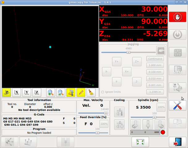
gmoccapy, a touch screen GUI based on Gscreen.
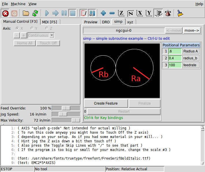
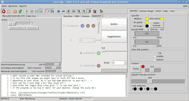
NGCGUI, a subroutine GUI that provides fill in the blanks programming of G code. It also supports concatenation of subroutine files to enable you to build a complete G code file without programming. The following screen shot shows NGCGUI imbedded into Axis.
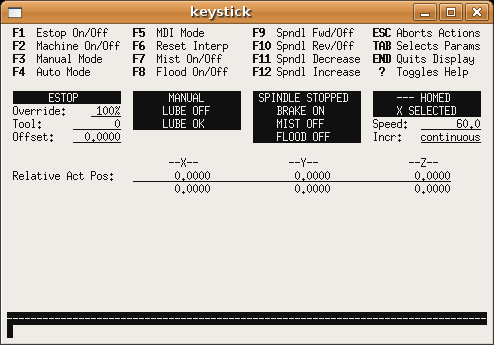
Keystick, a character-based screen graphics program suitable for minimal installations (without the X server running).
2.1. Additional Features
-
Xemc, an X-Windows program. A simulator configuration of Xemc can be ran from the configuration picker.
-
halui - a HAL based user interface which allows to control LinuxCNC using knobs and switches. See the HALUI chapter for more information.
-
linuxcncrsh - a telnet based user interface which allows commands to be sent to LinuxCNC from remote computers.
3. Virtual Control Panels
-
PyVCP a python based virtual control panel that can be added to the Axis GUI or be stand alone.
-
GladeVCP - a glade based virtual control panel that can be added to the Axis GUI or be stand alone.
See the PyVCP chapter and theGladeVCP chapter for more information on Virtual Control Panels.
4. Languages
LinuxCNC uses translation files to translate LinuxCNC User Interfaces into many languages. You just need to log in with the language you intend to use and when you start up LinuxCNC it comes up in that language. If your language has not been translated contact a developer on the IRC or the mailing list if you can assist in the translation.
5. Thinking Like a Machine Operator
This book will not even pretend that it can teach you to run a mill or a lathe. Becoming a machinist takes time and hard work. An author once said, "We learn from experience, if at all." Broken tools, gouged vices, and scars are the evidence of lessons taught. Good part finish, close tolerances, and careful work are the evidence of lessons learned. No machine, no computer program, can take the place of human experience.
As you begin to work with the LinuxCNC program, you will need to place yourself in the position of operator. You need to think of yourself in the role of the one in charge of a machine. It is a machine that is either waiting for your command or executing the command that you have just given it. Throughout these pages we will give information that will help you become a good operator of the LinuxCNC system. You will need some information right up front here so that the following pages will make sense to you.
6. Modes of Operation
When LinuxCNC is running, there are three different major modes used for inputting commands. These are Manual, Auto, and MDI. Changing from one mode to another makes a big difference in the way that the LinuxCNC control behaves. There are specific things that can be done in one mode that cannot be done in another. An operator can home an axis in manual mode but not in auto or MDI modes. An operator can cause the machine to execute a whole file full of G-codes in the auto mode but not in manual or MDI.
In manual mode, each command is entered separately. In human terms a manual command might be turn on coolant or jog X at 25 inches per minute. These are roughly equivalent to flipping a switch or turning the hand wheel for an axis. These commands are normally handled on one of the graphical interfaces by pressing a button with the mouse or holding down a key on the keyboard. In auto mode, a similar button or key press might be used to load or start the running of a whole program of G-code that is stored in a file. In the MDI mode the operator might type in a block of code and tell the machine to execute it by pressing the <return> or <enter> key on the keyboard.
Some motion control commands are available and will cause the same changes in motion in all modes. These include abort, estop, and feed rate override. Commands like these should be self explanatory.
The AXIS user interface hides some of the distinctions between Auto and the other modes by making Auto-commands available at most times. It also blurs the distinction between Manual and MDI because some Manual commands like Touch Off are actually implemented by sending MDI commands. It does this by automatically changing to the mode that is needed for the action the user has requested.