Updating LinuxCNC
This section describes how to upgrade LinuxCNC from version 2.7 to the new version. It assumes that you have an existing 2.7 install that you want to update.
To upgrade LinuxCNC from a version older than 2.7, you have to first upgrade your old install to 2.7, then follow these instructions to upgrade to the new version.
If you do not have an old version of LinuxCNC to upgrade, then you’re best off making a fresh install of the new version as described in the section Getting LinuxCNC.
1. Upgrade to the new version
The basic idea is to disable the old linuxcnc.org apt sources and add a new linuxcnc.org apt source, then upgrade the LinuxCNC packages.
The details will depend on which platform you’re running on. Run lsb_release -ic to find this information out:
> lsb_release -ic
Distributor ID: Debian
Codename:       wheezy
You should be running on Debian Wheezy (as above), or Ubuntu Precise, or Ubuntu Lucid.
1.1. Setting apt sources
-
Open the Software Sources window. The process for doing this differs slightly on the three supported platforms:
-
Debian Wheezy:
-
Click on Applications Menu, then System, then Synaptic Package Manager.
-
In Synaptic, click on the Settings menu, then click Repositories to open the Software Sources window.
-
-
Ubuntu Precise:
-
Click on the Dash Home icon in the top left.
-
In the Search field, type "software", then click on the Ubuntu Software Center icon.
-
In the Ubuntu Software Center window, click on the Edit menu, then click on Software Sources... to open the Software Sources window.
-
-
Ubuntu Lucid:
-
Click the System menu, then Administration, then Synaptic Package Manager.
-
In Synaptic, click on the Settings menu, then click Repositories to open the Software Sources window.
-
-
-
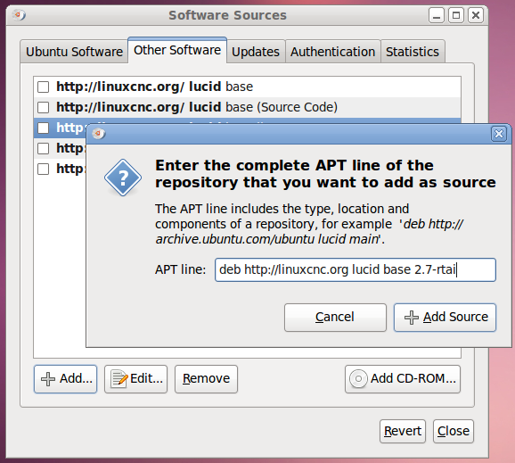
In the Software Sources window, select the Other Software tab.
-
Delete or un-check all the old linuxcnc.org entries (leave all non-linuxcnc.org lines as they are).
-
Click the Add button and add a new apt line. The line will be slightly different on the different platforms:
| Platform | apt source line |
|---|---|
Debian Wheezy |
deb http://linuxcnc.org wheezy base 2.7-rtai |
Ubuntu Precise |
deb http://linuxcnc.org precise base 2.7-rtai |
Ubuntu Lucid |
deb http://linuxcnc.org lucid base 2.7-rtai |
-
Click Add Source, then Close in the Software Sources window. If it pops up a window informing you that the information about available software is out-of-date, click the Reload button.
1.2. Upgrading to the new version
Now your computer knows where to get the new version of the software, next we need to install it.
The process again differs depending on your platform.
1.2.1. Debian Wheezy and Ubuntu Lucid
Debian Wheezy and Ubuntu Lucid both use the Synaptic Package Manager.
-
Open Synaptic using the instructions in Setting apt sources above.
-
Click the Reload button.
-
Use the Search function to search for linuxcnc.
-
Click the check box to mark the new linuxcnc and linuxcnc-doc-* packages for upgrade. The package manager may select a number of additional packages to be installed, to satisfy dependencies that the new linuxcnc package has.
-
Click the Apply button, and let your computer install the new package. The old linuxcnc package will be automatically upgraded to the new one.
1.3. Ubuntu Precise
-
Click on the Dash Home icon in the top left.
-
In the Search field, type "update", then click on the Update Manager icon.
-
Click the Check button to fetch the list of packages available.
-
Click the Install Updates button to install the new versions of all packages.
2. Updating Configuration Files
The new version of LinuxCNC differs from version 2.7 in some ways that may require changes to your machine configuration.
2.1. Distribution Configurations (updates for joints_axes)
The LinuxCNC distribution includes many example configurations organized in directory hierarchies named: by_machine, by_interface, and sim (simulated machines). These configurations are often used as starting points for making a new configuration, as examples for study, or as complete simulated machines that can run without special hardware or real-time kernels.
The configuration files in these directory trees have been updated for the changes required for the joints_axes updates.
2.2. Automatic updates (update_ini script for joints_axes)
Since the joints_axes updates require a number of changes to user ini files and their related halfiles, a script named update_ini is provided to automatically convert user configurations.
This script is invoked when a user starts an existing configuration for the first time after updating LinuxCNC. The script searches the user ini file for a [EMC]VERSION item. If this item 1) does not exist, or 2) exists and is set to the historical CVS value "$Revision$", or is a numerical value less than 1.0, then the update_ini script will popup a dialog to offer to edit the user files to create an updated configuration. If the user accepts, the configuration will be updated.
For example, if the user configuration is named bigmill.ini, the bigmill.ini file and its local associated hal files will be edited to incorporate joints_axes changes. All files of the initial configuration will be saved in a new directory named after the original configuration with a ".old" suffix (bigmill.old in the example).
The update_ini script handles all common user items that are found in basic machines employing identity kinematics. Less common items used in more complex machines may not be converted automatically. Examples of complex machine configurations include:
-
gantries with two joints for an axis
-
machines with jogwheels
-
robots with non-identity kinematics
-
configurations using haltcl files
The following subsections and the section for Hal Changes list items that may require additional user edits to ini or hal files.
2.3. Kinematics modules
The gentrivkins and gantrykins kinematics modules have been removed as their functionality is now available in the updated trivkins module.
The gentrivkins module has only been available in prior joints_axes branches. To convert, it is necessary to change the name.
Hal file examples:
was: loadrt gentrivkins
 is: loadrt trivkins

was: loadrt gentrivkins coordinates=xyyz
 is: loadrt trivkins    coordinates=xyyz
Configurations using gantrykins should be updated to use trivkins with the kinstype= parameter set to BOTH (for KINEMATICS_BOTH).
Hal file example:
was: loadrt gantrykins coordinates=xyyz
 is: loadrt trivkins   coordinates=xyyz kinstype=BOTH
See the trivkins man page for additional information ($ man trivkins)
Note: the most supported usage for specifying kinematics in joints_axes is to set values in the configuration ini file [KINS} section and then reference them within the specified [HAL]HALFILES ( .hal .tcl files). For example:
inifile:    [KINS]
            KINEMATICS = trivkins
            JOINTS = 3
            ...

halfile:    loadrt [KINS]KINEMATICS

haltclfile: loadrt $::KINS(KINEMATICS)
2.4. Lathe Configurations
Prior to joints_axes incorporation, lathes were often configured as if they were three axis (XYZ) machines with an unused axis (Y). This was convenient for sharing Hal files (especially for simulation configs) but required specification of [TRAJ]AXES =3, a dummy AXIS_Y section, and provisions for homing the unused Y coordinate. These arrangements are no longer required or recommended.
Historical lathe configurations used the default options for the trivkins kinematics module. These default options configure all axis letters (XYZABCUVW). With joints_axes incorporation, a more appropriate kinematics specification sets the coordinates to the exact ones used (XZ) and sets the number of joints accordingly to 2. There is no need for an ini file [AXIS_Y] section and only two [JOINT_N] sections need be defined.
Example ini file items for a lathe (only sections relevant to kinematics are shown):
[KINS]
KINEMATICS = trivkins coordinates=xz
JOINTS = 2

[TRAJ]
COORDINATES = XZ
...

[AXIS_X]
...

[AXIS_Z]
...

[JOINT_0]
...

[JOINT_1]
...
Note that some simulation configurations may still use the historical lathe configuration precedents.
2.5. Consistent Joints/Axes specifications
Ini file items that affect joints and axes usage must be consistent.
The motion kinematics module typically loaded with [KINS]KINEMATICS= must use a number of joints equal to the number specified with [KINS]JOINTS=.
The kinematics module must implement axis letters that are consistent with the specification used by the task module item [TRAJ]COORDINATES=.
Examples:
Three axis Cartesian machine using trivkins (KINEMATICS_IDENTITY):
  [KINS]KINEMATICS  = trivkins
  [KINS]JOINTS      = 3
  [TRAJ]COORDINATES = XYZ
Two axis lathe using trivkins (KINEMATICS_IDENTITY) with non-consecutive axis letters:
  [KINS]KINEMATICS  = trivkins coordinates=XZ
  [KINS]JOINTS      = 2
  [TRAJ]COORDINATES = XZ
Gantry using trivkins (KINEMATICS_IDENTITY) with duplicated axis letters:
  [KINS]KINEMATICS  = trivkins coordinates=XYYZ
  [KINS]JOINTS      = 4
  [TRAJ]COORDINATES = XYYZ
Gantry using trivkins (KINEMATICS_IDENTITY) with duplicated axis letters and a rotary axis with skipped axis letters (A,B skipped):
  [KINS]KINEMATICS  = trivkins coordinates=XYYZC
  [KINS]JOINTS      = 5
  [TRAJ]COORDINATES = XYYZC
Linear Delta Robot with non-identity kins (KINEMATICS_BOTH) working in Cartesian frame with an additional rotary coordinate:
  [KINS]KINEMATICS  = lineardeltakins
  [KINS]JOINTS      = 4
  [TRAJ]COORDINATES = XYZA
Note: Some general-purpose kinematics modules (like trivkins) implement identity kinematics with support for coordinate specification (axis letters). Axis letters may be omitted. Axis letters may be duplicated. Joints are assigned to axis letters in a defined manner ($ man trivkins).
Note: For trivkins module loading, do not include spaces about the = sign or letters:
This:     [KINS]KINEMATICS = trivkins coordinates=XZ
NOT This: [KINS]KINEMATICS = trivkins coordinates = X Z
Note: Custom kinematics modules that implement non-identity kinematics (like lineardeltakins) define machine-specific relationships between a set of coordinates and a set of joints. Typically, custom kinematics modules compute the joints-axes relationships within the custom module but it is important to use consistent settings for the related ini items: [KINS]JOINTS and [TRAJ]COORDINATES. The details will usually be explained in the module man page (for example, $ man lineardeltakins).
2.6. Home sequences
Negative values may be used for the ini file items named [JOINT_n]HOME_SEQUENCE. Prior to joints_axes incorporation a value of -1 or the ommission of the item indicated no sequence was applicable. Now, only omission of the item is used for that purpose.
2.7. Locking rotary indexer (updates for joints_axes)
With joints_axes, an indexer is a joint that can be homed (joint mode) but must also be unlocked from gcode. This requires a one-to-one correspondence between a single joint and an axis.
Specify the joint number that corresponds to a rotary axis (L = A,B, or C) with an ini file setting for the axis:
[AXIS_L]LOCKING_INDEXER_JOINT = joint_number_for_indexer
Specify that the joint is a locking indexer with an ini file setting for the joint (N is the joint_number_for_indexer):
[JOINT_N]LOCKING_INDEXER = 1
Hal pins can be created to coordinate use of a locking indicator joint:
   joint.N.unlock      (BIT output from Hal)
   joint.N.is-unlocked (BIT input  to   Hal)
To create these hal pins for locking joints, specify all joints that are used as locking indexers with the unlock_joints_mask parameter for the motmod module. (bit0(LSB)==>joint0, bit1==>joint1, etc.)
[EMCMOT]motmod unlock_joints_mask = BITMASK
As an example, consider a machine using trivkins kinematics with coordinates XYZB where B is a locking indexer. For trivkins, joint numbers (starting with 0) are assigned consecutively to the coordinates specified (axis coordinate letters may be omitted). For this example, X==>joint0, Y==>joint1, Z==>joint2, B==>joint3. The mask to specify joint 3 is 000001000 (binary) == 0x08 (hexadecimal)
The required ini file entries for this trivkins XYZB example are:
  [KINS]
  JOINTS = 4
  KINEMATICS = trivkins coordinates=XYZB
  ...

  [TRAJ]
  COORDINATES = XYZB
  ...

  [EMCMOT]
  EMCMOT = motmod unlock_joints_mask = 0x08
  ...

  [AXIS_B]
  LOCKING_INDEXER_JOINT = 3
  ...

  [JOINT_3]
  LOCKING_INDEXER = 1
  ...
For more complex kinematics, select the joint number as required — there must be a one-to-one correspondence between the rotary axis and the joint number.
(See the motion man page ($ man motion) for more information on motmod)
2.8. Stricter INI file syntax
Lines with numeric INI variables are no longer allowed to have trailing text. In earlier versions of LinuxCNC any text after the number was silently ignored, but as of this version such text is totally disallowed. This includes hash characters ("#"), which in this position are a part of the value, not a comment character.
For example, lines like this will no longer be accepted:
MAX_VELOCITY = 7.5 # This is the max velocity of the axis.
They could be transformed into pairs of lines like this:
# This is the max velocity of the axis.
MAX_VELOCITY = 7.5
3. Hal Changes (updates for joints_axes)
3.1. Wheel or MPG (manual pulse generator) jogging
Prior to incorporation of joints_axes updates, wheel jogging was supported in joint mode only and controlled with hal pins:
   bit   IN  axis.M.jog-enable
   float IN  axis.M.jog-scale
   s32   IN  axis.M.jog-counts
   bit   IN  axis.M.jog-vel-mode
where M is a number corresponding to an axis letter (0==>X, 1==>Y, etc.)
With incorporation of joints_axes updates, wheel jogging is available for joints in joint mode and for each axis coordinate in teleop mode. The controlling hal pins provided are:
   bit   IN  joint.N.jog-enable
   float IN  joint.N.jog-scale
   s32   IN  joint.N.jog-counts
   bit   IN  joint.N.jog-vel-mode

   bit   IN  axis.L.jog-enable
   float IN  axis.L.jog-scale
   s32   IN  axis.L.jog-counts
   bit   IN  axis.L.jog-vel-mode
where N is a joint number and L is an axis letter.
To use an MPG in identity kins configurations where there is a one-to-one correspondence of a joint number and an axis letter, it may be convenient to connect the corresponding hal pins. For example, if joint 1 corresponds exactly to axis letter y:
   net jora_1_y_enable   => joint.1.jog-enable => axis.y.jog-enable
   net jora_1_y_scale    => joint.1.jog-scale  => axis.y.jog-scale
   net jora_1_y_counts   => joint.1.jog-counts => axis.y.jog-counts
   net jora_1_y_vel-mode => joint.1.jog-counts => axis.y.jog-vel-mode
(The signal names jora_1_y_* are examples, names prior to conversion for joints_axes will depend upon the specific configuration details.)
Configurations with non-identity kinematics and configurations that use duplicated axis letters (for example, gantries using more than one joint for an axis coordinate) will require appropriate independent control logic to support both joint and teleop (world) jogging.
3.2. Ini Hal pins
Hal pins are created for ini file items for both joints ([JOINT_N] stanzas) and axes ([AXIS_L] stanzas):
For N = 0 ... [KINS](JOINTS -1)
Ini File Item              hal pin name
[JOINT_N]BACKLASH          ini.N.backlash
[JOINT_N]FERROR            ini.N.ferror
[JOINT_N]MIN_FERROR        ini.N.min_ferror
[JOINT_N]MIN_LIMIT         ini.N.min_limit
[JOINT_N]MAX_LIMIT         ini.N.max_limit
[JOINT_N]MAX_VELOCITY      ini.N.max_velocity
[JOINT_N]MAX_ACCELERATION  ini.N.max_acceleration
[JOINT_N]HOME              ini.N.home
[JOINT_N]HOME_OFFSET       ini.N.home_offset
For L = x y z a b c u v w:
Ini File Item              hal pin name
[AXIS_L]MIN_LIMIT          ini.L.min_limit
[AXIS_L]MAX_LIMIT          ini.L.max_limit
[AXIS_L]MAX_VELOCITY       ini.L.max_velocity
[AXIS_L]MAX_ACCELERATION   ini.L.max_acceleration
Note: In prior versions of LinuxCNC (before joints_axes updates), the hal pin names ini.N.* referred to axes with 0==>x, 1==>y, etc. (pins were created for all 9 axes) See the man page ($ man milltask) for more information
4. GUIs (updates for joints_axes)
4.1. Halui
Halui now supports teleop jogging resulting in some changed pin names and numerous new names for jogging-related pins.
See the man page ($ man halui) for all pin names.
4.1.1. TELEOP jogging (also called axis or world jogging)
New pins for teleop jogging are:
      new: halui.axis.jog-speed
      new: halui.axis.jog-deadband

      new: halui.axis.L.plus
      new: halui.axis.L.minus
           ... etc.
where L is a letter corresponding to one of the axis letters specified by [TRAJ]COORDINATES or selected for the axis selected by the halui.axis.L.select pins.
4.1.2. Joint jogging
All pins for joint jogging were renamed for specificity:
      was: halui.jog-speed          is: halui.joint.jog-speed
      was: halui.jog-deadband       is: halui.joint.jog-deadband

      was: halui.jog.N.plus         is: halui.joint.N.plus
      was: halui.jog.N.minus        is: halui.joint.N.minus
           ...  etc.                    ... etc.
where N is a joint number (0 … num_noints-1) or selected for the joint selected by the halui.joint.N.select pins.
4.1.3. Aditional pin renames
The hal pins for selected joints were renamed for consistency with related pins.
      was: halui.joint.selected.is_homed
       is: halui.joint.selected.is-homed

      was: halui.joint.selected.on-soft-limit
       is: halui.joint.selected.on-soft-min-limit
4.2. Axis gui
4.2.1. Kinematics Support
Identity
The axis gui continues to support identity kinematics configurations. This gui hides the distinctions of axes and joints in order to simplify the display and usage of simple machines.
Special cases
Some machines, typically gantrys, may use a configuration with more than one joint assigned to an axis letter. This can be done with the trivkins kinematics module using repeated coordinate letters. For example, a machine configured with ini settings:
[KINS]
KINEMATICS = trivkins coordinates=XYYZ kinstype=BOTH
...
[TRAJ]
COORDINATES = XYYZ
...
This machine, after homing, has a one-to-one correspondence between a single axis letter (Y) and a pair of joints (1,2). Using kinematics=BOTH allows control of individual joints in joint mode if/when required.
Non-identity
The axis gui supports configurations using non-identity kinematics with
-
Key binding ($) to toggle joint or teleop mode
-
Preview Tab display of joints or axes according to joint or teleop mode
-
Preview Tab display of Home and Limit icons in joint mode
-
Preview Tab display of All-homed and 'Any-limit icons in teleop mode
-
DRO Tab display of joint or axes according to joint or teleop mode
-
Provision to automatically switch to teleop mode after homing (see below for AUTO_TELEOP)
4.2.2. AUTO_TELEOP
The axis gui supports an option, [KINS]AUTO_TELEOP = N_seconds, to cause an automatic switch to teleop mode after homing. The N_seconds parameter specifes the maximum time to wait after initiating homing with the Home-All button. The setting is applicable only for kinematics that are not KINEMATICS_IDENTITY.
Usage Example (wait 20 seconds max):
[KINS]
AUTO_TELEOP = 20
...
4.2.3. Home icons
For identity kinematics, Home icons are shown for the correspoinding (one-to-one) axis letter when a joint is homed.
For non-identity kinematics, Home icons are shown for individual joints when a joint is homed in joint display mode. An All-homed icon is displayed for all axis letters when ALL joints are homed in world display mode.
4.2.4. Limit icons
For identity kinematics, Limit icons are shown for the corresponding (one-to-one) axis letter when a joint limit is active.
For non-identity kinematics, Limit icons are shown for individual joints when the joint limit is active in joint display mode. An Any-Limit icon is displayed if any joint is at a limit in teleop display mode.
4.2.5. Key bindings for a fourth axis
In the AXIS gui, jogging keys are assigned to axes in a configurable fashion. For 3-axis machines, XYZA machines, and lathes the default is the same as in 2.7. For other machines, the 4 pairs of jogging keys are assigned to the first 4 axes that exist in the order XYZ ABC UVW. These assignments can be controlled by new inifile directives in the [DISPLAY] section of the inifile
4.3. tklinuxcnc
4.3.1. Kinematics Support
The tklinuxcnc gui supports both identity and non-identity kinematics, includes gui radiobuttons and a key bindiing ($) for toggling joint and teleop modes. Jogging is supported in both joint and teleop modes. Note that the values used for jogging may not be appropriate for both modes.
4.4. touchy
The touchy gui continues to support the identity kinematics configurations that it supported prior to joints_axes incorporation. Jogging is done in joint mode (no coordination of joint/teleop modes with other guis is currently provided).
4.5. gscreen
The gscreen gui continues to support the identity kinematics configurations that it supported prior to joints_axes incorporation. Jogging is done in joint mode by default with limited support for teleop jogging when set by a contemporaneous, cooperating gui. Note that the values used for jogging may not be appropriate for both modes.
4.6. gmoccapy
The gmoccapy gui continues to support the identity kinematics configurations that it supported prior to joints_axes incorporation. Jogging is done in joint mode (no coordination of joint/teleop modes with other guis is currently provided).
4.7. linuxcnclcd
The linuxcnclcd gui has been updated to continue support for the identity kinematics supported prior to joints_axes incorporations. Jogging is done in joint mode. Compatiblity testsing awaits users with the required hardware.
4.8. linuxcncrsh
The jogging commands have been altered to accomodate both joint (free) and teleop (world) jogging.
    was: set jog      joint_number             speed
     is: set jog      joint_number|axis_letter speed

    was: set jog_incr joint_number             speed increment
     is: set jog_incr joint_number|axis_letter speed increment

    was: set jog_stop
     is: set jog_stop joint_number|axis_letter
Note: Test for teleop mode using command: get teleop_enable if TELEOP_ENABLE=YES, use axis_letter else use joint_number
Note: Formerly, the command set jog 0 1.234 would jog the zeroth axis (X) with requested speed=1.234 in any mode (free or teleop). This command now attemps to jog the zeroth joint (Joint0) provided the mode is free (not teleop). To jog the X axis, the mode must be teleop and the corresponding command is: set jog x 1.234
5. Simulator configurations (updates for joints axes)
5.1. Pre-joints_axes
Prior to joints_axes incorporation, the halfiles used in sim configs typically supported a common milling machine — a Cartesian system with trivial kinematics and three axes named X Y Z. Typical halfile entries:
[HAL]
HALFILE = core_sim.hal
HALFILE = sim_spindle_encoder.hal
HALFILE = axis_manualtoolchange.hal
HALFILE = simulated_home.hal
Lathe configs often shared the same halfiles and used the expedient method of specifying 3 axes with Y unused. More complex sim configs provided specific sets of halfiles according to the configuration purpose.
5.2. Post-joints_axes
With the incorporation of joints_axes functionality, may sims provided in the distribution now take advantage of a general purpose halfile that supports numerous configurations automatically. A typical sim config HALFILE specification is:
[HAL]
HALFILE = LIB:basic_sim.tcl
The basic_sim.tcl HALFILE supports a number of commonly required functions for any number of joints as specified by:
[KINS]
...
JOINTS = number_of_joints
...
Functions supported include:
-
ddts — differentiator hal components are loaded and connected for each joint (and xy, xyz for trivkins machines)
-
simulated_home — a sim_home_switch hal component is loaded and connected for each joint. The homing conditions are specified by the usual [JOINT_n]HOME_* ini file items.
-
use_hal_manualtoolchange — the user space hal_manualtoolchange component is loaded and connected.
-
sim_spindle — the sim_spindle component is loaded and connected to additional loaded hal components to simulate the inertia of a rotating spindle mass.
These functions are activated by default but can be excluded using options -no_make_ddts, -no_simulated_home, -no_use_hal_manualtoolchange, -no_sim_spindle. For example, to omit ddts:
HALFILE = LIB:basic_sim.tcl -no_make_ddts
Omitting one or more of the core functions allow a user to test without the function or add new HALFILEs to implement or expand on the functionality.
5.3. Notes
All components and connections made by LIB:basic_sim.tcl can be viewed using halcmd. The entire hal configuration (except for userspace components loaded with loadusr) can be saved to a file using:
$ halcmd save > hal.save
Use of LIB:basic_sim.tcl reduces the effort needed to make a simulation config since it handles most of the required component loading and hal connections.
The sim config Sample Configurations/sim/axis/minimal_xyz.ini demonstrates a working xyz configuration that uses LIB:basic_sim.tcl with a minimal number of ini file settings.