PnCconf is made to help build configurations that utilize specific Mesa Anything I/O products.
It can configure closed loop servo systems or hardware stepper systems. It uses a similar wizard approach as StepConf (used for software stepping, parallel port driven systems).
PnCconf is still in a development stage (Beta) so there are some bugs and lacking features. Please report bugs and suggestions to the LinuxCNC forum page or mailing list.
There are two trains of thought when using PnCconf:
One is to use PnCconf to always configure your system - if you decide to change options, reload PnCconf and allow it to configure the new options. This will work well if your machine is fairly standard and you can use custom files to add non standard features. PnCconf tries to work with you in this regard.
The other is to use PnCconf to build a config that is close to what you want and then hand edit everything to tailor it to your needs. This would be the choice if you need extensive modifications beyond PnCconf’s scope or just want to tinker with / learn about LinuxCNC.
You navigate the wizard pages with the forward, back, and cancel buttons there is also a help button that gives some help information about the pages, diagrams and an output page.
|
Tip
|
PnCconf’s help page should have the most up to date info and has additional details. |
1. Step by Step Instructions
2. Create or Edit
This allows you to select a previously saved configuration or create a new one. If you pick Modify a configuration and then press Next a file selection box will show. PnCconf preselects your last saved file. Choose the config you wish to edit. If you made any changes to the main HAL or INI files PnCconf will over write those files and those changes will be lost. Some files will not be over written and PnCconf places a note in those files. It also allows you to select desktop shortcut / launcher options. A desktop shortcut will place a folder icon on the desktop that points to your new configuration files. Otherwise you would have to look in your home folder under linuxcnc/configs.
A Desktop launcher will add an icon to the desktop for starting your config directly. You can also launch it from the main menu by using the Configuration Selector LinuxCNC found in CNC menu and selecting your config name.
3. Basic Machine Information
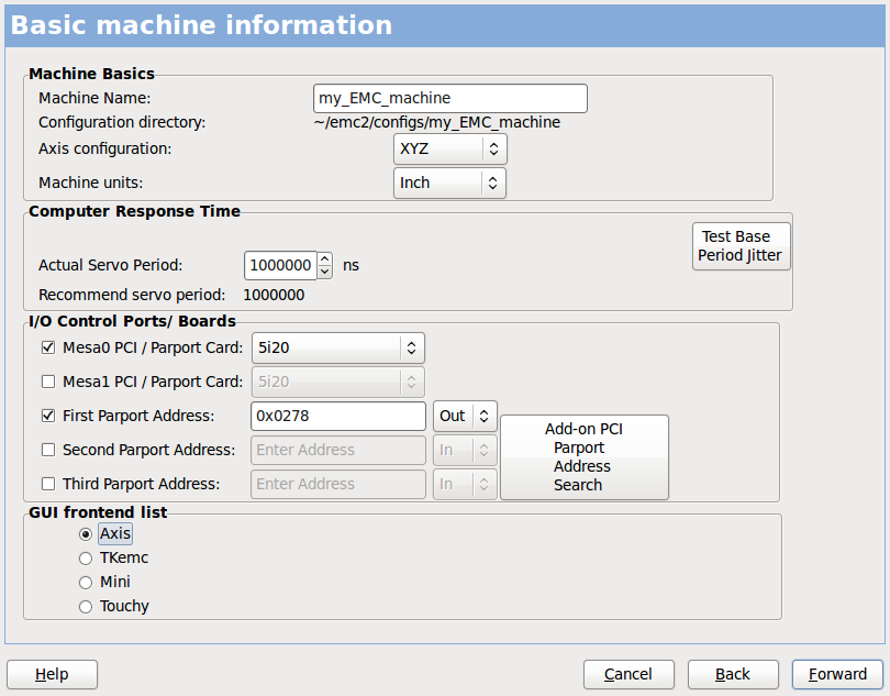
- Machine Basics
-
If you use a name with spaces PnCconf will replace the spaces with underscore (as a loose rule Linux doesn’t like spaces in names) Pick an axis configuration - this selects what type of machine you are building and what axes are available. The Machine units selector allows data entry of metric or imperial units in the following pages.
|
Tip
|
Defaults are not converted when using metric so make sure they are sane values! |
- Computer Response Time
-
The servo period sets the heart beat of the system. Latency refers to the amount of time the computer can be longer then that period. Just like a railroad, LinuxCNC requires everything on a very tight and consistent time line or bad things happen. LinuxCNC requires and uses a real time operating system, which just means it has a low latency ( lateness ) response time when LinuxCNC requires its calculations and when doing LinuxCNCs calculations it cannot be interrupted by lower priority requests (such as user input to screen buttons or drawing etc).
Testing the latency is very important and a key thing to check early. Luckily by using the Mesa card to do the work that requires the fastest response time (encoder counting and PWM generation) we can endure a lot more latency then if we used the parallel port for these things. The standard test in LinuxCNC is checking the BASE period latency (even though we are not using a base period). If you press the test base period jitter button, this launches the latency test window ( you can also load this directly from the applications/cnc panel ). The test mentions to run it for a few minutes but the longer the better. Consider 15 minutes a bare minimum and overnight even better. At this time use the computer to load things, use the net, use USB etc we want to know the worst case latency and to find out if any particular activity hurts our latency. We need to look at base period jitter. Anything under 20000 is excellent - you could even do fast software stepping with the machine 20000 - 50000 is still good for software stepping and fine for us. 50000 - 100000 is really not that great but could still be used with hardware cards doing the fast response stuff. So anything under 100000 is usable to us. If the latency is disappointing or you get a bad hiccup periodically you may still be able to improve it.
|
Tip
|
There is a user compiled list of equipment and the latency obtained on the LinuxCNC wiki: https://wiki.linuxcnc.org/cgi-bin/wiki.pl?Latency-Test Please consider adding your info to the list. Also on that page are links to info about fixing some latency problems. |
Now we are happy with the latency and must pick a servo period. In most cases a servo period of 1000000 ns is fine (that gives a 1 kHz servo calculation rate - 1000 calculations a second). If you are building a closed loop servo system that controls torque (current) rather then velocity (voltage) a faster rate would be better - something like 200000 (5 kHz calculation rate). The problem with lowering the servo rate is that it leaves less time available for the computer to do other things besides LinuxCNC’s calculations. Typically the display (GUI) becomes less responsive. You must decide on a balance. Keep in mind that if you tune your closed loop servo system then change the servo period you probably will need to tune them again.
- I/O Control Ports/Boards
-
PnCconf is capable of configuring machines that have up to two Mesa boards and three parallel ports. Parallel ports can only be used for simple low speed (servo rate) I/O.
- Mesa
-
You must choose at least one Mesa board as PnCconf will not configure the parallel ports to count encoders or output step or PWM signals. The mesa cards available in the selection box are based on what PnCconf finds for firmware on the systems. There are options to add custom firmware and/or blacklist (ignore) some firmware or boards using a preference file. If no firmware is found PnCconf will show a warning and use internal sample firmware - no testing will be possible. One point to note is that if you choose two PCI Mesa cards there currently is no way to predict which card is 0 and which is 1 - you must test - moving the cards could change their order. If you configure with two cards both cards must be installed for tests to function.
- Parallel Port
-
Up to 3 parallel ports (referred to as parports) can be used as simple I/O. You must set the address of the parport. You can either enter the Linux parallel port numbering system (0,1,or 2) or enter the actual address. The address for an on board parport is often 0x0278 or 0x0378 (written in hexadecimal) but can be found in the BIOS page. The BIOS page is found when you first start your computer you must press a key to enter it (such as F2). On the BIOS page you can find the parallel port address and set the mode such as SPP, EPP, etc on some computers this info is displayed for a few seconds during start up. For PCI parallel port cards the address can be found by pressing the parport address search button. This pops up the help output page with a list of all the PCI devices that can be found. In there should be a reference to a parallel port device with a list of addresses. One of those addresses should work. Not all PCI parallel ports work properly. Either type can be selected as in (maximum amount of input pins) or out (maximum amount of output pins).
- GUI Front-end list
-
This specifies the graphical display screens LinuxCNC will use. Each one has different option.
-
fully supports lathes.
-
is the most developed and used front-end
-
is designed to be used with mouse and keyboard
-
is tkinter based so integrates PyVCP (Python based virtual control panels) naturally.
-
has a 3D graphical window.
-
allows VCP integrated on the side or in center tab
-
hi contrast bright blue screen
-
separate graphics window
-
no VCP integration
-
Touchy was designed to be used with a touchscreen, some minimal physical switches and a MPG wheel.
-
requires cycle-start, abort, and single-step signals and buttons
-
It also requires shared axis MPG jogging to be selected.
-
is GTK based so integrates GladeVCP (virtual control panels) naturally.
-
allows VCP panels integrated in the center Tab
-
has no graphical window
-
look can be changed with custom themes
-
fully featured plasmac configuration based on the QtVCP infrastructure.
-
mouse/keyboard operation or touchscreen operation
-
no VCP integration
4. External Configuration
This page allows you to select external controls such as for jogging or overrides.
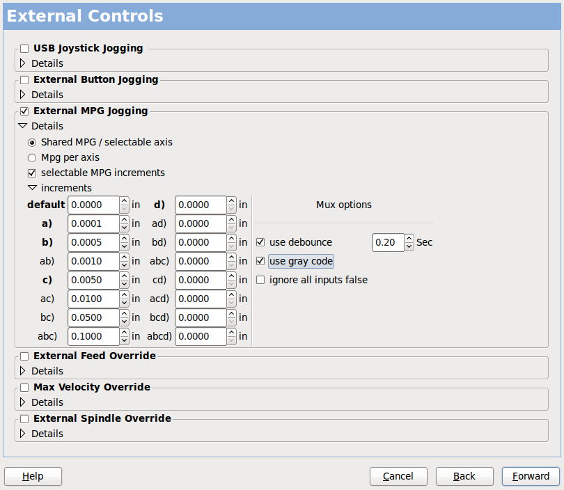
If you select a Joystick for jogging, You will need it always connected for LinuxCNC to load. To use the analog sticks for useful jogging you probably need to add some custom HAL code. MPG jogging requires a pulse generator connected to a MESA encoder counter. Override controls can either use a pulse generator (MPG) or switches (such as a rotary dial). External buttons might be used with a switch based OEM joystick.
- Joystick jogging
-
Requires a custom device rule to be installed in the system. This is a file that LinuxCNC uses to connect to Linux’s device list. PnCconf will help to prepare this file.
-
Search for device rule will search the system for rules, you can use this to find the name of devices you have already built with PnCconf.
-
Add a device rule will allow you to configure a new device by following the prompts. You will need your device available.
-
test device allows you to load a device, see its pin names and check its functions with halmeter.
-
joystick jogging uses HALUI and hal_input components.
- External buttons
-
allows jogging the axis with simple buttons at a specified jog rate. Probably best for rapid jogging.
- MPG Jogging
-
Allows you to use a Manual Pulse Generator to jog the machine’s axis.
MPG’s are often found on commercial grade machines. They output quadrature pulses that can be counted with a MESA encoder counter. PnCconf allows for an MPG per axis or one MPG shared with all axis. It allows for selection of jog speeds using switches or a single speed.
The selectable increments option uses the mux16 component. This component has options such as debounce and gray code to help filter the raw switch input.
- Overrides
-
PnCconf allows overrides of feed rates and/or spindle speed using a pulse generator (MPG) or switches (eg. rotary).
5. GUI Configuration
Here you can set defaults for the display screens, add virtual control panels (VCP), and set some LinuxCNC options..
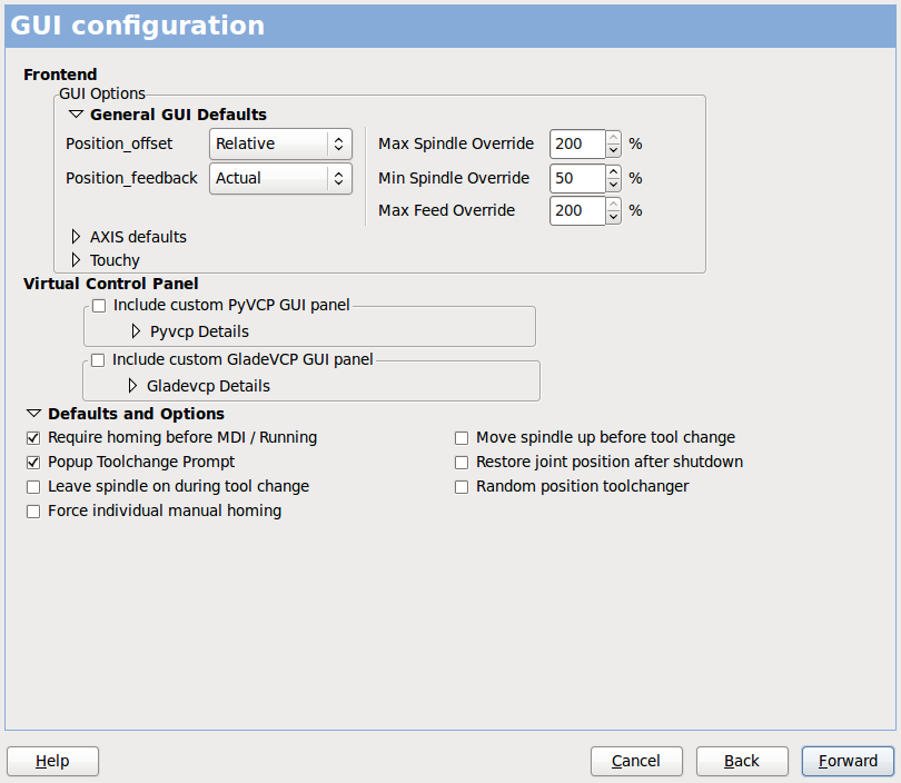
- Front-end GUI Options
-
The default options allows general defaults to be chosen for any display screen.
AXIS defaults are options specific to AXIS. If you choose size, position or force maximize options then PnCconf will ask if it is alright to overwrite a preference file (.axisrc). Unless you have manually added commands to this file it is fine to allow it. Position and force max can be used to move AXIS to a second monitor if the system is capable.
Touchy defaults are options specific to Touchy. Most of Touchy’s options can be changed while Touchy is running using the preference page. Touchy uses GTK to draw its screen, and GTK supports themes. Themes controls the basic look and feel of a program. You can download themes from the net or edit them yourself. There are a list of the current themes on the computer that you can pick from. To help some of the text to stand out PnCconf allows you to override the Themes’s defaults. The position and force max options can be used to move Touchy to a second monitor if the system is capable.
QtPlasmaC options are specific to QtPlasmac, any common options that are not required will be disabled. If QtPlasmac is selected then the following screen will be a user button setup screen that is specific to QtPlasmaC and VCP options will not be available.
- VCP options
-
Virtual Control Panels allow one to add custom controls and displays to the screen. AXIS and Touchy can integrate these controls inside the screen in designated positions. There are two kinds of VCPs - PyVCP which uses Tkinter to draw the screen and GladeVCP that uses GTK to draw the screen.
- PyVCP
-
PyVCPs screen XML file can only be hand built. PyVCPs fit naturally in with AXIS as they both use TKinter.
HAL pins are created for the user to connect to inside their custom HAL file. There is a sample spindle display panel for the user to use as-is or build on. You may select a blank file that you can later add your controls widgets to or select a spindle display sample that will display spindle speed and indicate if the spindle is at requested speed.
PnCconf will connect the proper spindle display HAL pins for you. If you are using AXIS then the panel will be integrated on the right side. If not using AXIS then the panel will be separate stand-alone from the front-end screen.
You can use the geometry options to size and move the panel, for instance to move it to a second screen if the system is capable. If you press the Display sample panel button the size and placement options will be honored.
- GladeVCP
-
GladeVCPs fit naturally inside of Touchy screen as they both use GTK to draw them, but by changing GladeVCP’s theme it can be made to blend pretty well in AXIS (try Redmond).
It uses a graphical editor to build its XML files. HAL pins are created for the user to connect to, inside of their custom HAL file.
GladeVCP also allows much more sophisticated (and complicated) programming interaction, which PnCconf currently doesn’t leverage (see GladeVCP in the manual).
PnCconf has sample panels for the user to use as-is or build on. With GladeVCP PnCconf will allow you to select different options on your sample display.
Under sample options select which ones you would like. The zero buttons use HALUI commands which you could edit later in the HALUI section.
Auto Z touch-off also requires the classic ladder touch-off program and a probe input selected. It requires a conductive touch-off plate and a grounded conductive tool. For an idea on how it works see:
Under Display Options, size, position, and force max can be used on a stand-alone panel for such things as placing the screen on a second monitor if the system is capable.
You can select a GTK theme which sets the basic look and feel of the panel. You Usually want this to match the front-end screen. These options will be used if you press the Display sample button. With GladeVCP depending on the front-end screen, you can select where the panel will display.
You can force it to be stand-alone or with AXIS it can be in the center or on the right side, with Touchy it can be in the center.
- Defaults and Options
-
-
Require homing before MDI / Running
-
If you want to be able to move the machine before homing uncheck this checkbox.
-
-
Popup Tool Prompt
-
Choose between an on screen prompt for tool changes or export standard signal names for a User supplied custom tool changer HAL file
-
-
Leave spindle on during tool change:
-
Used for lathes
-
-
Force individual manual homing
-
Move spindle up before tool change
-
Restore joint position after shutdown
-
Used for non-trivial kinematics machines
-
-
Random position tool changers
-
Used for tool changers that do not return the tool to the same pocket. You will need to add custom HAL code to support tool changers.
-
-
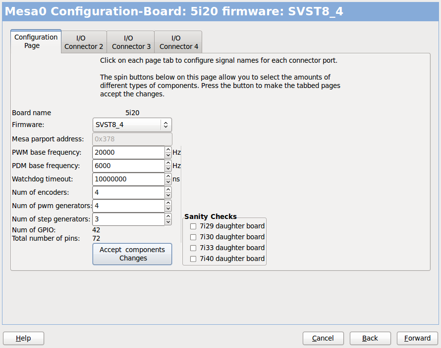
6. Mesa Configuration
The Mesa configuration pages allow one to utilize different firmwares. On the basic page you selected a Mesa card here you pick the available firmware and select what and how many components are available.
Parport address is used only with Mesa parport card, the 7i43. An on board parallel port usually uses 0x278 or 0x378 though you should be able to find the address from the BIOS page. The 7i43 requires the parallel port to use the EPP mode, again set in the BIOS page. If using a PCI parallel port the address can be searched for by using the search button on the basic page.
|
Note
|
Many PCI cards do not support the EPP protocol properly. |
PDM PWM and 3PWM base frequency sets the balance between ripple and linearity. If using Mesa daughter boards the docs for the board should give recommendations.
|
Important
|
It’s important to follow these to avoid damage and get the best performance. |
The 7i33 requires PDM and a PDM base frequency of 6 MHz
The 7i29 requires PWM and a PWM base frequency of 20 kHz
The 7i30 requires PWM and a PWM base frequency of 20 kHz
The 7i40 requires PWM and a PWM base frequency of 50 kHz
The 7i48 requires UDM and a PWM base frequency of 24 kHz- Watchdog time out
-
is used to set how long the MESA board will wait before killing outputs if communication is interrupted from the computer. Please remember Mesa uses active low outputs meaning that when the output pin is on, it is low (approx 0 volts) and if it is off the output in high (approx 5 volts) make sure your equipment is safe when in the off (watchdog bitten) state.
- Number of coders/PWM generators/STEP generators
-
You may choose the number of available components by deselecting unused ones. Not all component types are available with all firmware.
Choosing less then the maximum number of components allows one to gain more GPIO pins. If using daughter boards keep in mind you must not deselect pins that the card uses. For instance some firmware supports two 7i33 cards, If you only have one you may deselect enough components to utilize the connector that supported the second 7i33. Components are deselected numerically by the highest number first then down with out skipping a number. If by doing this the components are not where you want them then you must use a different firmware. The firmware dictates where, what and the max amounts of the components. Custom firmware is possible, ask nicely when contacting the LinuxCNC developers and Mesa. Using custom firmware in PnCconf requires special procedures and is not always possible - though I try to make PnCconf as flexible as possible.
After choosing all these options press the Accept Component Changes button and PnCconf will update the I/O setup pages. Only I/O tabs will be shown for available connectors, depending on the Mesa board.
7. Mesa I/O Setup
The tabs are used to configure the input and output pins of the Mesa boards. PnCconf allows one to create custom signal names for use in custom HAL files.
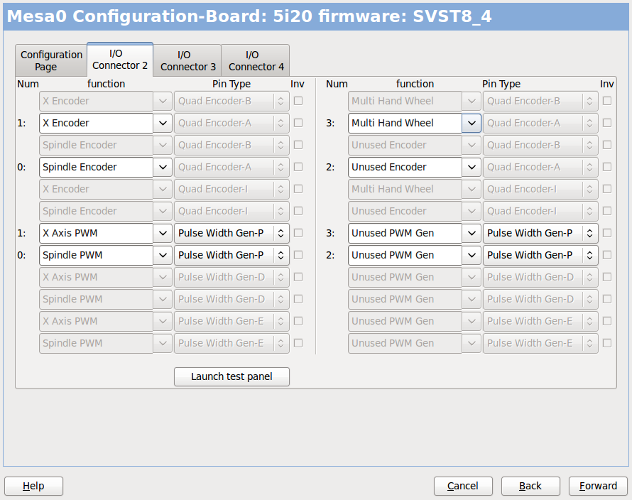
On this tab with this firmware the components are setup for a 7i33 daughter board, usually used with closed loop servos. Note the component numbers of the encoder counters and PWM drivers are not in numerical order. This follows the daughter board requirements.
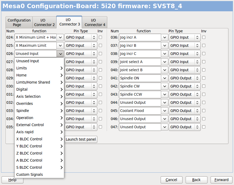
On this tab all the pins are GPIO. Note the 3 digit numbers - they will match the HAL pin number. GPIO pins can be selected as input or output and can be inverted.
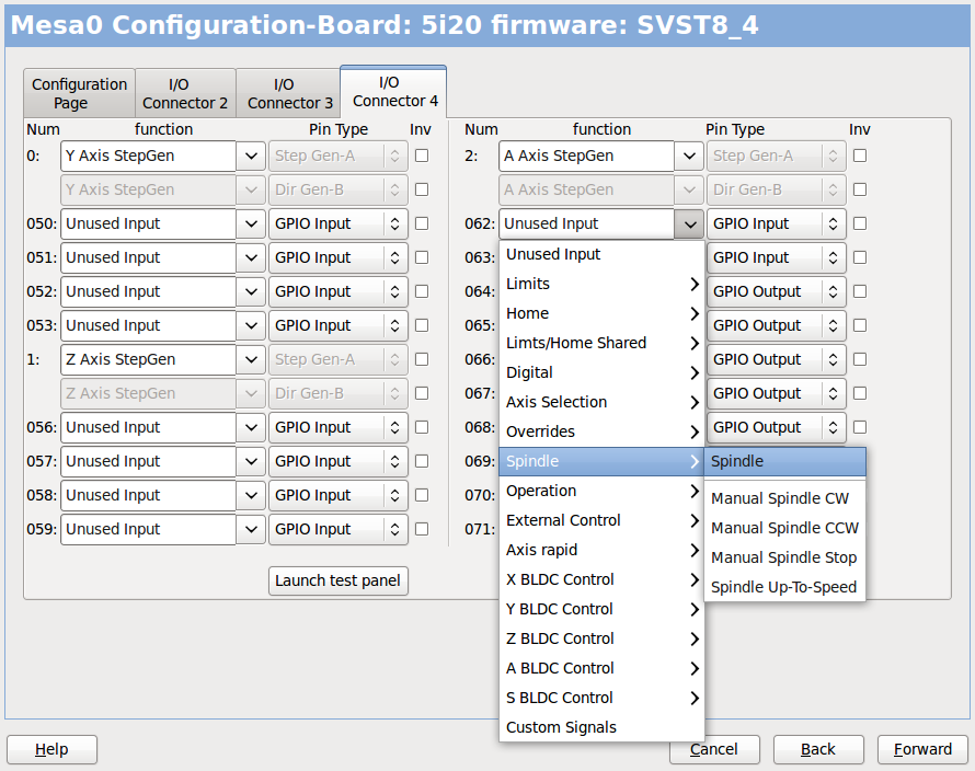
On this tab there are a mix of step generators and GPIO. Step generators output and direction pins can be inverted. Note that inverting a Step Gen-A pin (the step output pin) changes the step timing. It should match what your controller expects.
8. Parallel port configuration
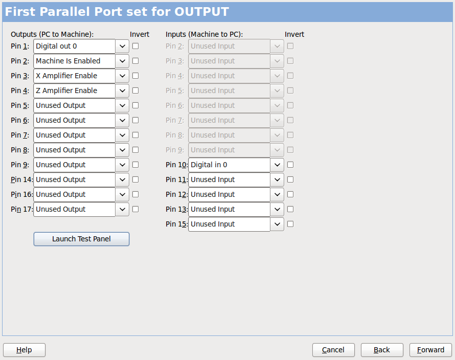
The parallel port can be used for simple I/O similar to Mesa’s GPIO pins.
9. Axis Configuration
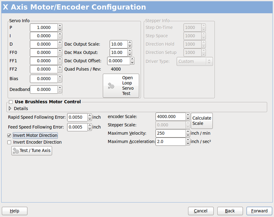
This page allows configuring and testing of the motor and/or encoder combination. If using a servo motor an open loop test is available, if using a stepper a tuning test is available.
- Open Loop Test
-
An open loop test is important as it confirms the direction of the motor and encoder. The motor should move the axis in the positive direction when the positive button is pushed and also the encoder should count in the positive direction. The axis movement should follow the Machinery’s Handbook
["axis nomenclature" in the chapter "Numerical Control" in the "Machinery’s Handbook" published by Industrial Press.]
standards or AXIS graphical display will not make much sense. Hopefully the help page and diagrams can help figure this out. Note that axis directions are based on TOOL movement not table movement. There is no acceleration ramping with the open loop test so start with lower DAC numbers. By moving the axis a known distance one can confirm the encoder scaling. The encoder should count even without the amp enabled depending on how power is supplied to the encoder.
|
Warning
|
If the motor and encoder do not agree on counting direction then the servo will run away when using PID control. |
Since at the moment PID settings can not be tested in PnCconf the settings are really for when you re-edit a config - enter your tested PID settings.
- DAC scale
-
DAC scaling, max output and offset are used to tailor the DAC output.
- Compute DAC
-
These two values are the scale and offset factors for the axis output to the motor amplifiers. The second value (offset) is subtracted from the computed output (in volts), and divided by the first value (scale factor), before being written to the D/A converters. The units on the scale value are in true volts per DAC output volts. The units on the offset value are in volts. These can be used to linearize a DAC.
Specifically, when writing outputs, the LinuxCNC first converts the desired output in quasi-SI units to raw actuator values, e.g., volts for an amplifier DAC. This scaling looks like: The value for scale can be obtained analytically by doing a unit analysis, i.e., units are [output SI units]/[actuator units]. For example, on a machine with a velocity mode amplifier such that 1 volt results in 250 mm/sec velocity. Note that the units of the offset are in machine units, e.g., mm/sec, and they are pre-subtracted from the sensor readings. The value for this offset is obtained by finding the value of your output which yields 0.0 for the actuator output. If the DAC is linearized, this offset is normally 0.0.
The scale and offset can be used to linearize the DAC as well, resulting in values that reflect the combined effects of amplifier gain, DAC non-linearity, DAC units, etc. To do this, follow this procedure:
-
Build a calibration table for the output, driving the DAC with a desired voltage and measuring the result:
| Raw | Measured |
|---|---|
-10 |
-9.93 |
-9 |
-8.83 |
0 |
-0.96 |
1 |
-0.03 |
9 |
9.87 |
10 |
10.07 |
-
Do a least-squares linear fit to get coefficients a, b such that meas=a*raw+b
-
Note that we want raw output such that our measured result is identical to the commanded output. This means
-
cmd=a*raw+b
-
raw=(cmd-b)/a
-
-
As a result, the a and b coefficients from the linear fit can be used as the scale and offset for the controller directly.
- MAX OUTPUT
-
The maximum value for the output of the PID compensation that is written to the motor amplifier, in volts. The computed output value is clamped to this limit. The limit is applied before scaling to raw output units. The value is applied symmetrically to both the plus and the minus side.
- Tuning Test
-
The tuning test unfortunately only works with stepper based systems. Again confirm the directions on the axis is correct. Then test the system by running the axis back and forth, If the acceleration or max speed is too high you will lose steps. While jogging, Keep in mind it can take a while for an axis with low acceleration to stop. Limit switches are not functional during this test. You can set a pause time so each end of the test movement. This would allow you to set up and read a dial indicator to see if you are losing steps.
- Stepper Timing
-
Stepper timing needs to be tailored to the step controller’s requirements. PnCconf supplies some default controller timing or allows custom timing settings. See https://wiki.linuxcnc.org/cgi-bin/wiki.pl?Stepper_Drive_Timing for some more known timing numbers (feel free to add ones you have figured out). If in doubt use large numbers such as 5000 this will only limit max speed.
- Brushless Motor Control
-
These options are used to allow low level control of brushless motors using special firmware and daughter boards. It also allows conversion of HALL sensors from one manufacturer to another. It is only partially supported and will require one to finish the HAL connections. Contact the mail-list or forum for more help.
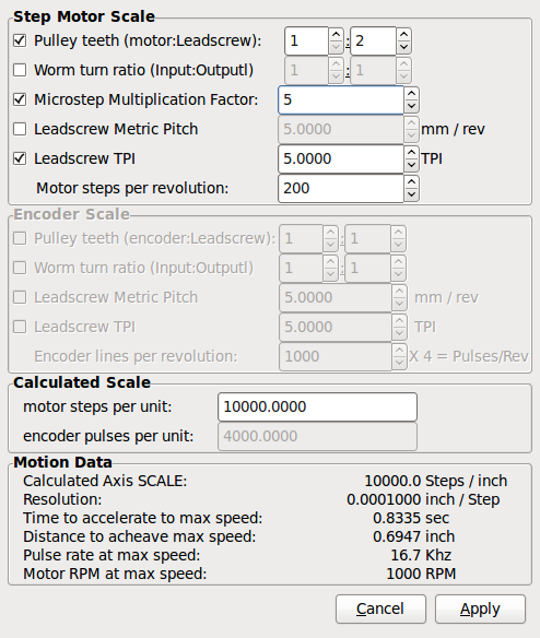
The scale settings can be directly entered or one can use the calculate scale button to assist. Use the check boxes to select appropriate calculations. Note that pulley teeth requires the number of teeth not the gear ratio. Worm turn ratio is just the opposite it requires the gear ratio. If your happy with the scale press apply otherwise push cancel and enter the scale directly.
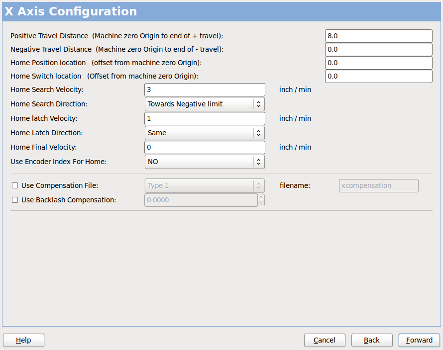
Also refer to the diagram tab for two examples of home and limit switches. These are two examples of many different ways to set homing and limits.
|
Important
|
It is very important to start with the axis moving in the right direction or else getting homing right is very difficult! |
Remember positive and negative directions refer to the TOOL not the table as per the Machinists handbook.
- On a typical knee or bed mill
-
-
when the TABLE moves out that is the positive Y direction
-
when the TABLE moves left that is the positive X direction
-
when the TABLE moves down that is the positive Z direction
-
when the HEAD moves up that is the positive Z direction
-
- On a typical lathe
-
-
when the TOOL moves right, away from the chuck
-
that is the positive Z direction
-
when the TOOL moves toward the operator
-
that is the positive X direction. Some lathes have X opposite (e.g., tool on back side), that will work fine but AXIS graphical display can not be made to reflect this.
-
When using homing and / or limit switches LinuxCNC expects the HAL signals to be true when the switch is being pressed / tripped. If the signal is wrong for a limit switch then LinuxCNC will think the machine is on end of limit all the time. If the home switch search logic is wrong LinuxCNC will seem to home in the wrong direction. What it actually is doing is trying to BACK off the home switch.
- Decide on limit switch location
-
Limit switches are the back up for software limits in case something electrical goes wrong, e.g., in case of a servo runaway. Limit switches should be placed so that the machine does not hit the physical end of the axis movement. Remember the axis will coast past the contact point if moving fast. Limit switches should be active low on the machine, i.e., power runs through the switches all the time - a loss of power (open switch) trips. While one could wire them the other way, this is fail safe. This may need to be inverted so that the HAL signal in LinuxCNC in active high - a TRUE means the switch was tripped. When starting LinuxCNC if you get an on-limit warning, and axis is NOT tripping the switch, inverting the signal is probably the solution. (use HALMETER to check the corresponding HAL signal eg. joint.0.pos-lim-sw-in X axis positive limit switch)
- Decide on the home switch location
-
If you are using limit switches You may as well use one as a home switch. A separate home switch is useful if you have a long axis that in use is usually a long way from the limit switches or moving the axis to the ends presents problems of interference with material. Note, a long shaft in a lathe makes it hard to home to limits with out the tool hitting the shaft, so a separate home switch closer to the middle may be better. If you have an encoder with index then the home switch acts as a course home and the index will be the actual home location.
- Decide on the MACHINE ORIGIN position
-
MACHINE ORIGIN is what LinuxCNC uses to reference all user coordinate systems from. I can think of little reason it would need to be in any particular spot. There are only a few G-codes that can access the MACHINE COORDINATE system.( G53, G30 and G28 ) If using tool-change-at-G30 option having the origin at the tool change position may be convenient. By convention, it may be easiest to have the ORIGIN at the home switch.
- Decide on the (final) HOME POSITION
-
this just places the carriage at a consistent and convenient position after LinuxCNC figures out where the ORIGIN is.
- Measure / calculate the positive / negative axis travel distances
-
Move the axis to the origin. Mark a reference on the movable slide and the non-movable support (so they are in line) move the machine to the end of limits. Measure between the marks that is one of the travel distances. Move the table to the other end of travel. Measure the marks again. That is the other travel distance. If the ORIGIN is at one of the limits then that travel distance will be zero.
- (machine) ORIGIN
-
The Origin is the MACHINE zero point. (not the zero point you set your cutter / material at). LinuxCNC uses this point to reference everything else from. It should be inside the software limits. LinuxCNC uses the home switch location to calculate the origin position (when using home switches or must be manually set if not using home switches.
- Travel distance
-
This is the maximum distance the axis can travel in each direction. This may or may not be able to be measured directly from origin to limit switch. The positive and negative travel distances should add up to the total travel distance.
- POSITIVE TRAVEL DISTANCE
-
This is the distance the Axis travels from the Origin to the positive travel distance or the total travel minus the negative travel distance. You would set this to zero if the origin is positioned at the positive limit. The will always be zero or a positive number.
- NEGATIVE TRAVEL DISTANCE
-
This is the distance the Axis travels from the Origin to the negative travel distance. or the total travel minus the positive travel distance. You would set this to zero if the origin is positioned at the negative limit. This will always be zero or a negative number. If you forget to make this negative PnCconf will do it internally.
- (Final) HOME POSITION
-
This is the position the home sequence will finish at. It is referenced from the Origin so can be negative or positive depending on what side of the Origin it is located. When at the (final) home position if you must move in the Positive direction to get to the Origin, then the number will be negative.
- HOME SWITCH LOCATION
-
This is the distance from the home switch to the Origin. It could be negative or positive depending on what side of the Origin it is located. When at the home switch location if you must move in the Positive direction to get to the Origin, then the number will be negative. If you set this to zero then the Origin will be at the location of the limit switch (plus distance to find index if used).
- Home Search Velocity
-
Course home search velocity in units per minute.
- Home Search Direction
-
Sets the home switch search direction either negative (i.e., towards negative limit switch) or positive (i.e., towards positive limit switch).
- Home Latch Velocity
-
Fine Home search velocity in units per minute.
- Home Final Velocity
-
Velocity used from latch position to (final) home position in units per minute. Set to 0 for max rapid speed.
- Home latch Direction
-
Allows setting of the latch direction to the same or opposite of the search direction.
- Use Encoder Index For Home
-
LinuxCNC will search for an encoder index pulse while in the latch stage of homing.
- Use Compensation File
-
Allows specifying a Comp filename and type. Allows sophisticated compensation. See AXIS Section of the INI chapter.
- Use Backlash Compensation
-
Allows setting of simple backlash compensation. Can not be used with Compensation File. See AXIS Section of the INI chapter.
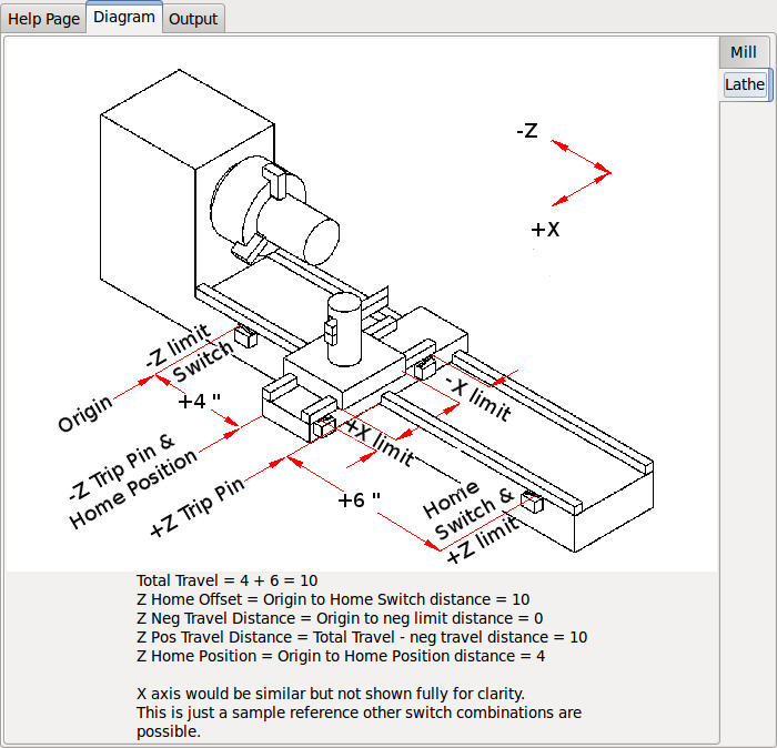
The diagram should help to demonstrate an example of limit switches and standard axis movement directions. In this example the Z axis was two limit switches, the positive switch is shared as a home switch. The MACHINE ORIGIN (zero point) is located at the negative limit. The left edge of the carriage is the negative trip pin and the right the positive trip pin. We wish the FINAL HOME POSITION to be 4 inches away from the ORIGIN on the positive side. If the carriage was moved to the positive limit we would measure 10 inches between the negative limit and the negative trip pin.
10. Spindle Configuration
If you select spindle signals then this page is available to configure spindle control.
|
Tip
|
Many of the option on this page will not show unless the proper option was selected on previous pages! |
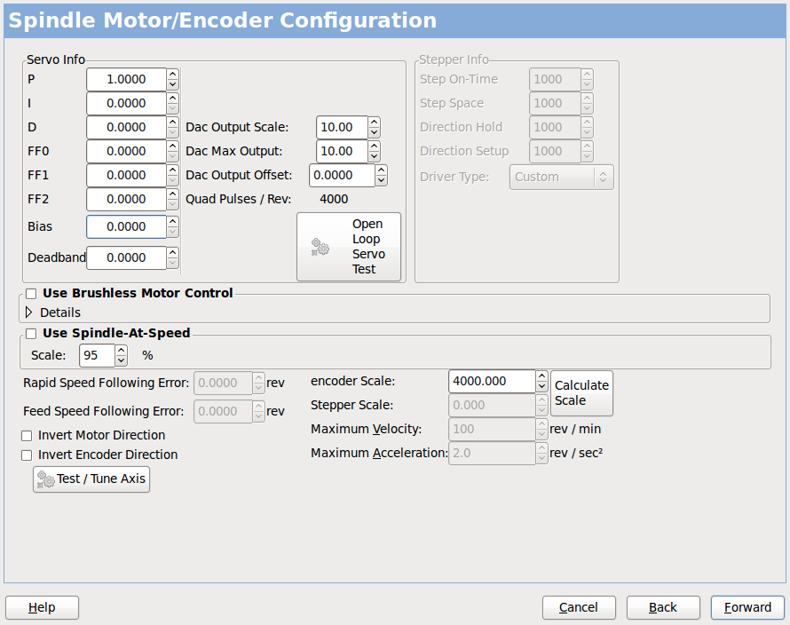
This page is similar to the axis motor configuration page.
There are some differences:
-
Unless one has chosen a stepper driven spindle there is no acceleration or velocity limiting.
-
There is no support for gear changes or ranges.
-
If you picked a VCP spindle display option then spindle-at-speed scale and filter settings may be shown.
-
Spindle-at-speed allows LinuxCNC to wait till the spindle is at the requested speed before moving the axis. This is particularly handy on lathes with constant surface feed and large speed diameter changes. It requires either encoder feedback or a digital spindle-at-speed signal typically connected to a VFD drive.
-
If using encoder feedback, you may select a spindle-at-speed scale setting that specifies how close the actual speed must be to the requested speed to be considered at-speed.
-
If using encoder feedback, the VCP speed display can be erratic - the filter setting can be used to smooth out the display. The encoder scale must be set for the encoder count / gearing used.
-
If you are using a single input for a spindle encoder you must add the line: setp hm2_7i43.0.encoder.00.counter-mode 1 (changing the board name and encoder number to your requirements) into a custom HAL file. See the Encoders Section in Hostmot2 for more info about counter mode.
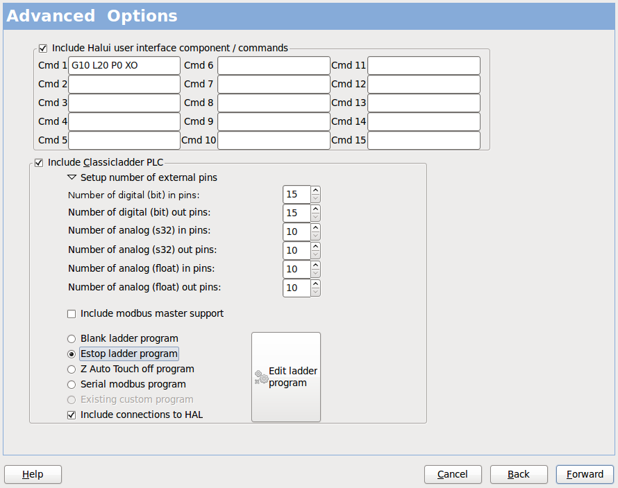
11. Advanced Options
This allows setting of HALUI commands and loading of ClassicLadder and sample ladder programs. If you selected GladeVCP options such as for zeroing axis, there will be commands showing. See the HALUI Chapter for more info on using custom halcmds. There are several ladder program options. The Estop program allows an external ESTOP switch or the GUI frontend to throw an Estop. It also has a timed lube pump signal. The Z auto touch-off is with a touch-off plate, the GladeVCP touch-off button and special HALUI commands to set the current user origin to zero and rapid clear. The serial modbus program is basically a blank template program that sets up ClassicLadder for serial modbus. See the ClassicLadder Chapter in the manual.
12. HAL Components
On this page you can add additional HAL components you might need for custom HAL files. In this way one should not have to hand edit the main HAL file, while still allowing user needed components.
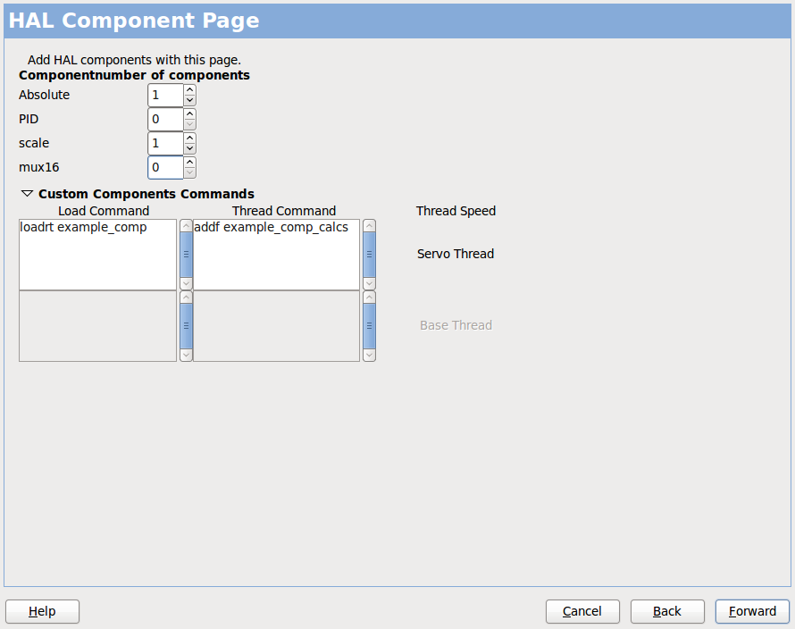
The first selection is components that pncconf uses internally. You may configure pncconf to load extra instances of the components for your custom HAL file.
Select the number of instances your custom file will need, PnCconf will add what it needs after them.
Meaning if you need 2 and PnCconf needs 1 PnCconf will load 3 instances and use the last one.
- Custom Component Commands
-
This selection will allow you to load HAL components that PnCconf does not use. Add the loadrt or loadusr command, under the heading loading command Add the addf command under the heading Thread command. The components will be added to the thread between reading of inputs and writing of outputs, in the order you write them in the thread command.
13. Advanced Usage Of PnCconf
PnCconf does its best to allow flexible customization by the user. PnCconf has support for custom signal names, custom loading of components, custom HAL files and custom firmware.
There are also signal names that PnCconf always provides regardless of options selected, for user’s custom HAL files With some thought most customizations should work regardless if you later select different options in PnCconf.
Eventually if the customizations are beyond the scope of PnCconf’s frame work you can use PnCconf to build a base config or use one of LinuxCNC’s sample configurations and just hand edit it to what ever you want.
- Custom Signal Names
-
If you wish to connect a component to something in a custom HAL file write a unique signal name in the combo entry box. Certain components will add endings to your custom signal name:
Encoders will add < customname > +:
-
position
-
count
-
velocity
-
index-enable
-
reset
Steppers add:
-
enable
-
counts
-
position-cmd
-
position-fb
-
velocity-fb
PWM add:
-
enable
-
value
GPIO pins will just have the entered signal name connected to it
In this way one can connect to these signals in the custom HAL files and still have the option to move them around later.
- Custom Signal Names
-
The HAL Components page can be used to load components needed by a user for customization.
- Loading Custom Firmware
-
PnCconf searches for firmware on the system and then looks for the XML file that it can convert to what it understands. These XML files are only supplied for officially released firmware from the LinuxCNC team. To utilize custom firmware one must convert it to an array that PnCconf understands and add its file path to PnCconf’s preference file. By default this path searches the desktop for a folder named custom_firmware and a file named firmware.py.
The hidden preference file is in the user’s home file, is named .pncconf-preferences and require one to select show hidden files in your file manager to see and edit it or on the command line you use ls with the -a option. The contents of this file can be seen when you first load PnCconf - press the help button and look at the output page.
Ask on the LinuxCNC mail-list or forum for info about converting custom firmware. Not all firmware can be utilized with PnCconf.
- Custom HAL Files
-
There are four custom files that you can use to add HAL commands to:
-
custom.hal is for HAL commands that don’t have to be run after the GUI frontend loads. It is run after the configuration-named HAL file.
-
custom_postgui.hal is for commands that must be run after AXIS loads or a standalone PyVCP display loads.
-
custom_gvcp.hal is for commands that must be run after GladeVCP is loaded.
-
shutdown.hal is for commands to run when LinuxCNC shuts down in a controlled manner.
-