1. Целевая аудитория
Этот документ представляет собой сборник заметок о внутреннем устройстве LinuxCNC. Он в первую очередь представляет интерес для разработчиков, однако большая часть информации здесь может быть также интересна системным интеграторам и другим, кому просто интересно узнать, как работает LinuxCNC. Большая часть этой информации уже устарела и никогда не проверялась на точность.
2. Организация
В документации будет глава для каждого из основных компонентов LinuxCNC, а также глава(ы), описывающие, как они работают вместе. Этот документ в значительной степени находится в стадии разработки, и его макет может измениться в будущем.
3. Термины и определения
-
AXIS - An axis is one of the nine degrees of freedom that define a tool position in three-dimensional Cartesian space. Those nine axes are referred to as X, Y, Z, A, B, C, U, V, and W. The linear orthogonal coordinates X, Y, and Z determine where the tip of the tool is positioned. The angular coordinates A, B, and C determine the tool orientation. A second set of linear orthogonal coordinates U, V, and W allows tool motion (typically for cutting actions) relative to the previously offset and rotated axes. Unfortunately "axis" is also sometimes used to mean a degree of freedom of the machine itself, such as the saddle, table, or quill of a Bridgeport type milling machine. On a Bridgeport this causes no confusion, since movement of the table directly corresponds to movement along the X axis. However, the shoulder and elbow joints of a robot arm and the linear actuators of a hexapod do not correspond to movement along any Cartesian axis, and in general it is important to make the distinction between the Cartesian axes and the machine degrees of freedom. In this document, the latter will be called joints, not axes. The GUIs and some other parts of the code may not always follow this distinction, but the internals of the motion controller do.
-
JOINT — Сочленение — это одна из подвижных частей машины. Сочленения отличаются от осей, хотя эти два термина иногда (неправильно) используются для обозначения одного и того же. В LinuxCNC сочленение — это физический объект, который можно перемещать, а не координата в пространстве. Например, пиноль, колено, седло и стол фрезера Bridgeport представляют собой сочленения. Плечо, локоть и запястье руки робота являются сочленениями, как и линейные приводы гексапода. С каждым сочленением связан двигатель или привод определенного типа. Сочленения не обязательно соответствуют осям X, Y и Z, хотя для машин с тривиальной кинематикой это может иметь место. Даже на этих машинах положение сочленения и положение оси — это принципиально разные вещи. В этом документе термины сочленение и ось используются осторожно, с учетом их различных значений. К сожалению, это не обязательно так везде. В частности, ГИП’ы станков с тривиальной кинематикой могут затушевывать или полностью скрывать различие между сочленениями и осями. Кроме того, в файле INI используется термин ось для данных, которые точнее было бы описать как данные сочленения, например масштабирование входных и выходных данных и т. д.
|
Note
|
Это различие было сделано в версии 2.8 LinuxCNC. В INI-файле появился новый раздел [JOINT_<num>]. Многие параметры, которые раньше относились к разделу [AXIS_<letter>], теперь находятся в новом разделе. Другие разделы, такие как [KINS], также принимают новые параметры, соответствующие этому. Был предоставлен скрипт обновления для преобразования старых файлов INI в новую конфигурацию осей/сочленений. |
-
POSE - A pose is a fully specified position in 3D Cartesian space. In the LinuxCNC motion controller, when we refer to a pose we mean an EmcPose structure, containing six linear coordinates (X, Y, Z, U, V, and W) and three angular ones (A, B, and C).
-
coord, or coordinated mode, means that all articulations are synchronized and they move together as directed by the higher-level code. It is the normal mode when machining. In coordinated mode, commands are assumed to be given in the Cartesian reference frame, and if the machine is not Cartesian, the commands are translated by the kinematics to drive each joint into the joint space as needed.
-
free means that commands are interpreted in joint space. It is used to manually move (jog) individual joints, although it does not prevent them from moving multiple joints at once (I think). Homing is also done in free mode; in fact, machines with non-trivial kinematics must be homed before they can go into coord or teleop mode.
-
teleop is the mode you probably need if you are jogging with a hexapod. The jog commands implemented by the motion controller are joint jogs, which work in free mode. But if you want to move a hexapod or similar machine along a cartesian axis in particular, you must operate more than one joint. That’s what teleop is for.
4. Architecture overview
There are four components contained in the LinuxCNC Architecture: a motion controller (EMCMOT), a discrete IO controller (EMCIO), a task executor which coordinates them (EMCTASK) and several text-mode and graphical User Interfaces. Each of them will be described in the current document, both from the design point of view and from the developers point of view (where to find needed data, how to easily extend/modify things, etc.).
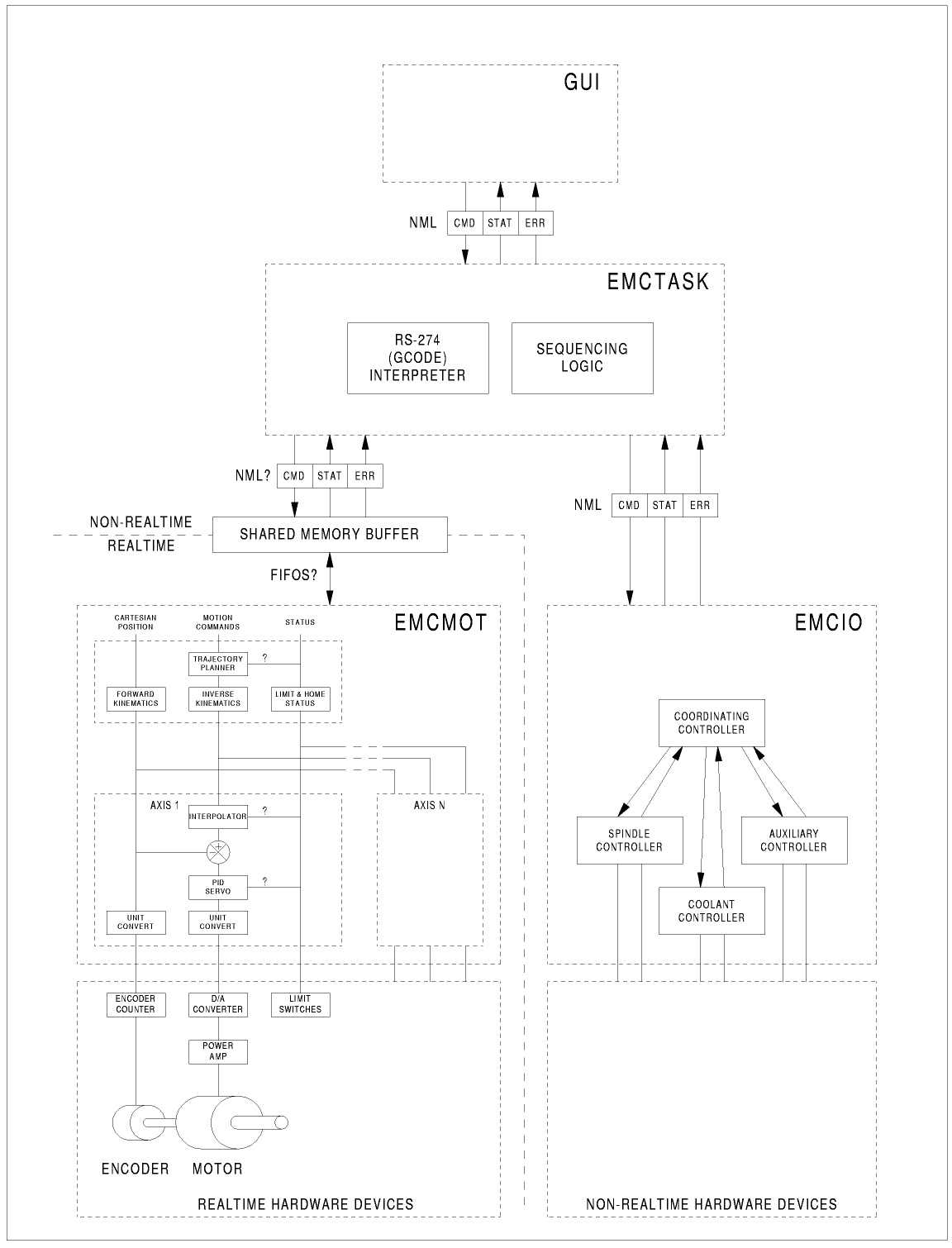
4.1. LinuxCNC software architecture
At the coarsest level, LinuxCNC is a hierarchy of three controllers: the task level command handler and program interpreter, the motion controller, and the discrete I/O controller. The discrete I/O controller is implemented as a hierarchy of controllers, in this case for spindle, coolant, and auxiliary (e.g., estop) subsystems. The task controller coordinates the actions of the motion and discrete I/O controllers. Their actions are programmed in conventional numerical control "G and M code" programs, which are interpreted by the task controller into NML messages and sent to the motion.
5. Motion Controller Introduction
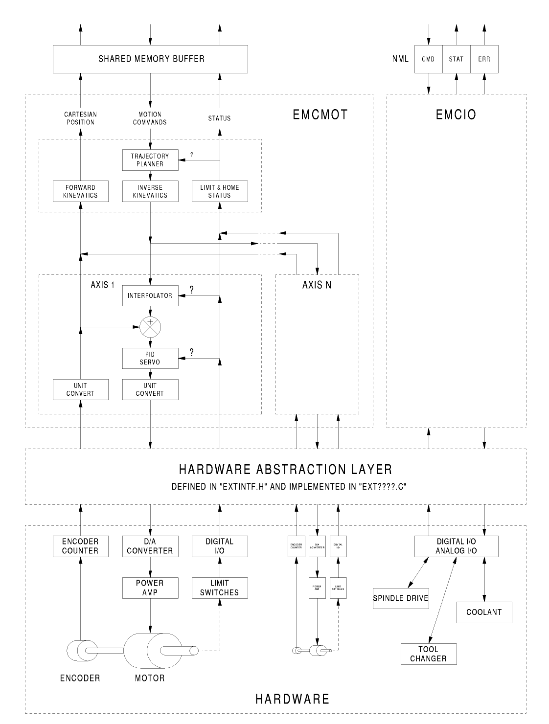
The motion controller is a realtime component. It receives motion control commands from the non-realtime parts of LinuxCNC (i.e. the G-code interpreter/Task, GUIs, etc) and executes those commands within its realtime context. The communication from non-realtime context to realtime context happens via a message-passing IPC mechanism using shared memory, and via the Hardware Abstraction Layer (HAL).
The status of the motion controller is made available to the rest of LinuxCNC through the same message-passing shared memory IPC, and through HAL.
The motion controller interacts with the motor controllers and other realtime and non-realtime hardware using HAL.
Этот документ предполагает, что читатель имеет базовое представление о HAL, и используются такие термины, как контакты HAL, сигналы HAL и т. д., без их объяснения. Дополнительную информацию о HAL см. в HAL Руководство . Другая глава этого документа в конечном итоге будет посвящена внутреннему устройству самого HAL, но в этой главе мы используем только HAL API, как определено в src/hal/hal.h.
5.1. Motion Controller Modules
The realtime functions of the motion controller are implemented with realtime modules — userspace shared objects for Preempt-RT systems or kernel modules for some kernel-mode realtime implementations such as RTAI:
-
tpmod - trajectory planning
-
homemod - homing functions
-
motmod - processes NML commands and controls hardware via HAL
-
kinematics module - performs forward (joints-->coordinates) and inverse (coordinates->joints) kinematics calculations
LinuxCNC is started by a linuxcnc script which reads a configuration INI file and starts all needed processes. For realtime motion control, the script first loads the default tpmod and homemod modules and then loads the kinematics and motion modules according to settings in halfiles specified by the INI file.
Custom (user-built) homing or trajectory-planning modules can be used in place of the default modules via INI file settings or command line options. Custom modules must implement all functions used by the default modules. The halcompile utility can be used to create a custom module.
6. Block diagrams and Data Flow
The following figure is a block diagram of a joint controller. There is one joint controller per joint. The joint controllers work at a lower level than the kinematics, a level where all joints are completely independent. All the data for a joint is in a single joint structure. Some members of that structure are visible in the block diagram, such as coarse_pos, pos_cmd, and motor_pos_fb.
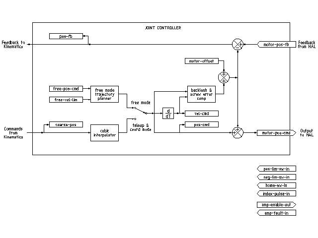
The above figure shows five of the seven sets of position information that form the main data flow through the motion controller. The seven forms of position data are as follows:
-
emcmotStatus->carte_pos_cmd - This is the desired position, in Cartesian coordinates. It is updated at the traj rate, not the servo rate. In coord mode, it is determined by the traj planner. In teleop mode, it is determined by the traj planner? In free mode, it is either copied from actualPos, or generated by applying forward kins to (2) or (3).
-
emcmotStatus->joints[n].coarse_pos - This is the desired position, in joint coordinates, but before interpolation. It is updated at the traj rate, not the servo rate. In coord mode, it is generated by applying inverse kins to (1) In teleop mode, it is generated by applying inverse kins to (1) In free mode, it is copied from (3), I think.
-
'emcmotStatus->joints[n].pos_cmd - This is the desired position, in joint coords, after interpolation. A new set of these coords is generated every servo period. In coord mode, it is generated from (2) by the interpolator. In teleop mode, it is generated from (2) by the interpolator. In free mode, it is generated by the free mode traj planner.
-
emcmotStatus->joints[n].motor_pos_cmd - This is the desired position, in motor coords. Motor coords are generated by adding backlash compensation, lead screw error compensation, and offset (for homing) to (3). It is generated the same way regardless of the mode, and is the output to the PID loop or other position loop.
-
emcmotStatus->joints[n].motor_pos_fb - This is the actual position, in motor coords. It is the input from encoders or other feedback device (or from virtual encoders on open loop machines). It is "generated" by reading the feedback device.
-
emcmotStatus->joints[n].pos_fb - This is the actual position, in joint coordinates. It is generated by subtracting offset, lead screw error compensation, and backlash compensation from (5). It is generated the same way regardless of the operating mode.
-
emcmotStatus->carte_pos_fb - This is the actual position, in Cartesian coordinates. It is updated at the traj rate, not the servo rate. Ideally, actualPos would always be calculated by applying forward kinematics to (6). However, forward kinematics may not be available, or they may be unusable because one or more axes aren’t homed. In that case, the options are: A) fake it by copying (1), or B) admit that we don’t really know the Cartesian coordinates, and simply don’t update actualPos. Whatever approach is used, I can see no reason not to do it the same way regardless of the operating mode. I would propose the following: If there are forward kins, use them, unless they don’t work because of unhomed axes or other problems, in which case do (B). If no forward kins, do (A), since otherwise actualPos would never get updated.
7. Homing
7.1. Homing state diagram

7.2. Another homing diagram

8. Commands
The commands are implemented by a large switch statement in the function emcmotCommandHandler(), which is called at the servo rate. More on that function later.
There are approximately 44 commands - this list is still under construction.
|
Note
|
The cmd_code_t enumeration, in motion.h, contains 73 commands, but the switch statement in command.c contemplates only 70 commands (as of 6/5/2020). ENABLE_WATCHDOG / DISABLE_WATCHDOG commands are in motion-logger.c. Maybe they are obsolete. The SET_TELEOP_VECTOR command only appears in motion-logger.c, with no effect other than its own log. |
8.1. ABORT
The ABORT command simply stops all motion. It can be issued at any time, and will always be accepted. It does not disable the motion controller or change any state information, it simply cancels any motion that is currently in progress.
[It seems that the higher level code (TASK and above) also use ABORT to clear faults. Whenever there is a persistent fault (such as being outside the hardware limit switches), the higher level code sends a constant stream of ABORTs to the motion controller trying to make the fault go away. Thousands of them…. That means that the motion controller should avoid persistent faults. This needs to be looked into.]
8.1.1. Requirements
None. The command is always accepted and acted on immediately.
8.1.2. Results
In free mode, the free mode trajectory planners are disabled. That results in each joint stopping as fast as its accel (decel) limit allows. The stop is not coordinated. In teleop mode, the commanded Cartesian velocity is set to zero. I don’t know exactly what kind of stop results (coordinated, uncoordinated, etc), but will figure it out eventually. In coord mode, the coord mode trajectory planner is told to abort the current move. Again, I don’t know the exact result of this, but will document it when I figure it out.
8.2. FREE
The FREE command puts the motion controller in free mode. Free mode means that each joint is independent of all the other joints. Cartesian coordinates, poses, and kinematics are ignored when in free mode. In essence, each joint has its own simple trajectory planner, and each joint completely ignores the other joints. Some commands (like Joint JOG and HOME) only work in free mode. Other commands, including anything that deals with Cartesian coordinates, do not work at all in free mode.
8.2.1. Requirements
The command handler applies no requirements to the FREE command, it will always be accepted. However, if any joint is in motion (GET_MOTION_INPOS_FLAG() == FALSE), then the command will be ignored. This behavior is controlled by code that is now located in the function set_operating_mode() in control.c, that code needs to be cleaned up. I believe the command should not be silently ignored, instead the command handler should determine whether it can be executed and return an error if it cannot.
8.2.2. Results
If the machine is already in free mode, nothing. Otherwise, the machine is placed in free mode. Each joint’s free mode trajectory planner is initialized to the current location of the joint, but the planners are not enabled and the joints are stationary.
8.3. TELEOP
The TELEOP command places the machine in teleoperating mode. In teleop mode, movement of the machine is based on Cartesian coordinates using kinematics, rather than on individual joints as in free mode. However the trajectory planner per se is not used, instead movement is controlled by a velocity vector. Movement in teleop mode is much like jogging, except that it is done in Cartesian space instead of joint space. On a machine with trivial kinematics, there is little difference between teleop mode and free mode, and GUIs for those machines might never even issue this command. However for non-trivial machines like robots and hexapods, teleop mode is used for most user commanded jog type movements.
8.3.1. Requirements
The command handler will reject the TELEOP command with an error message if the kinematics cannot be activated because the one or more joints have not been homed. In addition, if any joint is in motion (GET_MOTION_INPOS_FLAG() == FALSE), then the command will be ignored (with no error message). This behavior is controlled by code that is now located in the function set_operating_mode() in control.c. I believe the command should not be silently ignored, instead the command handler should determine whether it can be executed and return an error if it cannot.
8.3.2. Results
If the machine is already in teleop mode, nothing. Otherwise the machine is placed in teleop mode. The kinematics code is activated, interpolators are drained and flushed, and the Cartesian velocity commands are set to zero.
8.4. COORD
The COORD command places the machine in coordinated mode. In coord mode, movement of the machine is based on Cartesian coordinates using kinematics, rather than on individual joints as in free mode. In addition, the main trajectory planner is used to generate motion, based on queued LINE, CIRCLE, and/or PROBE commands. Coord mode is the mode that is used when executing a G-code program.
8.4.1. Requirements
The command handler will reject the COORD command with an error message if the kinematics cannot be activated because the one or more joints have not been homed. In addition, if any joint is in motion (GET_MOTION_INPOS_FLAG() == FALSE), then the command will be ignored (with no error message). This behavior is controlled by code that is now located in the function set_operating_mode() in control.c. I believe the command should not be silently ignored, instead the command handler should determine whether it can be executed and return an error if it cannot.
8.4.2. Results
If the machine is already in coord mode, nothing. Otherwise, the machine is placed in coord mode. The kinematics code is activated, interpolators are drained and flushed, and the trajectory planner queues are empty. The trajectory planner is active and awaiting a LINE, CIRCLE, or PROBE command.
8.5. ENABLE
The ENABLE command enables the motion controller.
8.5.1. Requirements
None. The command can be issued at any time, and will always be accepted.
8.5.2. Results
If the controller is already enabled, nothing. If not, the controller is enabled. Queues and interpolators are flushed. Any movement or homing operations are terminated. The amp-enable outputs associated with active joints are turned on. If forward kinematics are not available, the machine is switched to free mode.
8.6. DISABLE
The DISABLE command disables the motion controller.
8.6.1. Requirements
None. The command can be issued at any time, and will always be accepted.
8.6.2. Results
If the controller is already disabled, nothing. If not, the controller is disabled. Queues and interpolators are flushed. Any movement or homing operations are terminated. The amp-enable outputs associated with active joints are turned off. If forward kinematics are not available, the machine is switched to free mode.
8.7. ENABLE_AMPLIFIER
The ENABLE_AMPLIFIER command turns on the amp enable output for a single output amplifier, without changing anything else. Can be used to enable a spindle speed controller.
8.7.1. Requirements
None. The command can be issued at any time, and will always be accepted.
8.7.2. Results
Currently, nothing. (A call to the old extAmpEnable function is currently commented out.) Eventually it will set the amp enable HAL pin true.
8.8. DISABLE_AMPLIFIER
The DISABLE_AMPLIFIER command turns off the amp enable output for a single amplifier, without changing anything else. Again, useful for spindle speed controllers.
8.8.1. Requirements
None. The command can be issued at any time, and will always be accepted.
8.8.2. Results
Currently, nothing. (A call to the old extAmpEnable function is currently commented out.) Eventually it will set the amp enable HAL pin false.
8.9. ACTIVATE_JOINT
The ACTIVATE_JOINT command turns on all the calculations associated with a single joint, but does not change the joint’s amp enable output pin.
8.9.1. Requirements
None. The command can be issued at any time, and will always be accepted.
8.9.2. Results
Calculations for the specified joint are enabled. The amp enable pin is not changed, however, any subsequent ENABLE or DISABLE commands will modify the joint’s amp enable pin.
8.10. DEACTIVATE_JOINT
The DEACTIVATE_JOINT command turns off all the calculations associated with a single joint, but does not change the joint’s amp enable output pin.
8.10.1. Requirements
None. The command can be issued at any time, and will always be accepted.
8.10.2. Results
Calculations for the specified joint are enabled. The amp enable pin is not changed, and subsequent ENABLE or DISABLE commands will not modify the joint’s amp enable pin.
8.11. ENABLE_WATCHDOG
The ENABLE_WATCHDOG command enables a hardware based watchdog (if present).
8.11.1. Requirements
None. The command can be issued at any time, and will always be accepted.
8.11.2. Results
Currently nothing. The old watchdog was a strange thing that used a specific sound card. A new watchdog interface may be designed in the future.
8.12. DISABLE_WATCHDOG
Команда DISABLE_WATCHDOG отключает аппаратный сторожевой таймер (если он есть).
8.12.1. Requirements
None. The command can be issued at any time, and will always be accepted.
8.12.2. Results
Currently nothing. The old watchdog was a strange thing that used a specific sound card. A new watchdog interface may be designed in the future.
8.13. PAUSE
Команда PAUSE останавливает планировщик траектории. Она не действует в свободном режиме или режиме телеоперации. На данный момент я не знаю, останавливает ли он все движения немедленно или завершает текущее движение, а затем делает паузу, прежде чем вытащить другое движение из очереди.
8.13.1. Requirements
None. The command can be issued at any time, and will always be accepted.
8.13.2. Results
Планировщик траектории останавливается.
8.14. RESUME
Команда RESUME перезапускает планировщик траектории, если он был приостановлен. Она не действует в свободном или телеоперативном режиме, а также если планировщик не поставлен на паузу.
8.14.1. Requirements
None. The command can be issued at any time, and will always be accepted.
8.14.2. Results
Планировщик траектории возобновляет работу.
8.15. STEP
Команда STEP перезапускает планировщик траектории, если он был приостановлен, и указывает планировщику снова остановиться, когда он достигает определенной точки. Он не действует в свободном режиме или режиме телеоперации. На данный момент я точно не знаю, как это работает. Я добавлю сюда дополнительную документацию, когда углублюсь в планировщик траектории.
8.15.1. Requirements
None. The command can be issued at any time, and will always be accepted.
8.15.2. Results
Планировщик траектории возобновляет работу, а затем приостанавливается, когда достигает определенной точки.
8.16. SCALE
Команда SCALE масштабирует все ограничения скорости и команды на указанную величину. Она используется для реализации переопределения скорости подачи и других подобных функций. Масштабирование работает в свободном, телеоперативном и координатном режимах и влияет на все, включая скорость позиционирования в исходную позицию и т. д. Однако ограничения скорости отдельных сочленений не затрагиваются.
8.16.1. Requirements
None. The command can be issued at any time, and will always be accepted.
8.16.2. Results
Все команды скорости масштабируются указанной константой.
8.17. OVERRIDE_LIMITS
Команда OVERRIDE_LIMITS предотвращает срабатывание пределов до окончания следующей команды JOG. Обычно она используется для того, чтобы станок мог быть отведен с концевого выключателя после срабатывания. (На самом деле эту команду можно использовать для переопределения ограничений или для отмены предыдущего переопределения.)
8.17.1. Requirements
Никаких. Команда может быть подана в любое время и всегда будет принята. (Я думаю, что это должно работать только в свободном режиме.)
8.17.2. Results
Ограничения для всех сочленений переопределяются до окончания следующей команды JOG. (В настоящее время это не работает… как только получена команда OVERRIDE_LIMITS, пределы игнорируются до тех пор, пока другая команда OVERRIDE_LIMITS не активирует их снова.)
8.18. HOME
Команда HOME инициирует последовательность возврата в исходное положения указанного сочленения. Фактическая последовательность возврата определяется рядом параметров конфигурации и может варьироваться от простой установки текущего положения на ноль до многоступенчатого поиска концевого выключателя исходной позиции и индексного импульса с последующим перемещением в произвольное исходное положение. Для получения дополнительной информации о последовательности возврата см. раздел возврат в исходную позицию в Руководстве системного разработчика.
8.18.1. Requirements
Команда будет молча игнорироваться, если станок не находится в свободном режиме.
8.18.2. Results
Любая медленная подача или другое движение сочленения прерывается, и начинается последовательность возврата в исходное положение.
8.19. JOG_CONT
The JOG_CONT command initiates a continuous jog on a single joint. A continuous jog is generated by setting the free mode trajectory planner’s target position to a point beyond the end of the joint’s range of travel. This ensures that the planner will move constantly until it is stopped by either the joint limits or an ABORT command. Normally, a GUI sends a JOG_CONT command when the user presses a jog button, and ABORT when the button is released.
8.19.1. Requirements
The command handler will reject the JOG_CONT command with an error message if machine is not in free mode, or if any joint is in motion (GET_MOTION_INPOS_FLAG() == FALSE), or if motion is not enabled. It will also silently ignore the command if the joint is already at or beyond its limit and the commanded jog would make it worse.
8.19.2. Results
The free mode trajectory planner for the joint identified by emcmotCommand->axis is activated, with a target position beyond the end of joint travel, and a velocity limit of emcmotCommand->vel. This starts the joint moving, and the move will continue until stopped by an ABORT command or by hitting a limit. The free mode planner accelerates at the joint accel limit at the beginning of the move, and will decelerate at the joint accel limit when it stops.
8.20. JOG_INCR
The JOG_INCR command initiates an incremental jog on a single joint. Incremental jogs are cumulative, in other words, issuing two JOG_INCR commands that each ask for 0.100 inches of movement will result in 0.200 inches of travel, even if the second command is issued before the first one finishes. Normally incremental jogs stop when they have traveled the desired distance, however they also stop when they hit a limit, or on an ABORT command.
8.20.1. Requirements
The command handler will silently reject the JOG_INCR command if machine is not in free mode, or if any joint is in motion (GET_MOTION_INPOS_FLAG() == FALSE), or if motion is not enabled. It will also silently ignore the command if the joint is already at or beyond its limit and the commanded jog would make it worse.
8.20.2. Results
The free mode trajectory planner for the joint identified by emcmotCommand->axis is activated, the target position is incremented/decremented by emcmotCommand->offset, and the velocity limit is set to emcmotCommand->vel. The free mode trajectory planner will generate a smooth trapezoidal move from the present position to the target position. The planner can correctly handle changes in the target position that happen while the move is in progress, so multiple JOG_INCR commands can be issued in quick succession. The free mode planner accelerates at the joint accel limit at the beginning of the move, and will decelerate at the joint accel limit to stop at the target position.
8.21. JOG_ABS
The JOG_ABS command initiates an absolute jog on a single joint. An absolute jog is a simple move to a specific location, in joint coordinates. Normally absolute jogs stop when they reach the desired location, however they also stop when they hit a limit, or on an ABORT command.
8.21.1. Requirements
The command handler will silently reject the JOG_ABS command if machine is not in free mode, or if any joint is in motion (GET_MOTION_INPOS_FLAG() == FALSE), or if motion is not enabled. It will also silently ignore the command if the joint is already at or beyond its limit and the commanded jog would make it worse.
8.21.2. Results
The free mode trajectory planner for the joint identified by emcmotCommand->axis is activated, the target position is set to emcmotCommand->offset, and the velocity limit is set to emcmotCommand->vel. The free mode trajectory planner will generate a smooth trapezoidal move from the present position to the target position. The planner can correctly handle changes in the target position that happen while the move is in progress. If multiple JOG_ABS commands are issued in quick succession, each new command changes the target position and the machine goes to the final commanded position. The free mode planner accelerates at the joint accel limit at the beginning of the move, and will decelerate at the joint accel limit to stop at the target position.
8.22. SET_LINE
The SET_LINE command adds a straight line to the trajectory planner queue.
(More later)
8.23. SET_CIRCLE
Команда SET_CIRCLE добавляет круговое движение в очередь планировщика траектории.
(More later)
8.24. SET_TELEOP_VECTOR
Команда SET_TELEOP_VECTOR указывает контроллеру движения двигаться по определенному вектору в декартовом пространстве.
(More later)
8.25. PROBE
Команда PROBE указывает контроллеру движения двигаться в направлении определенной точки в декартовом пространстве, останавливая и записывая его положение, если срабатывает вход датчика.
(More later)
8.26. CLEAR_PROBE_FLAG
Команда CLEAR_PROBE_FLAG используется для сброса входа датчика при подготовке к команде PROBE. (Вопрос: почему команда PROBE не должна автоматически сбрасывать ввод?)
(More later)
8.27. SET_xix
Существует примерно 15 команд SET_xxx, где xxx — это имя некоторого параметра конфигурации. Ожидается, что будет еще несколько команд SET по мере добавления дополнительных параметров. Я хотел бы найти более аккуратный способ установки и чтения параметров конфигурации. Существующие методы требуют добавления множества строк кода в несколько файлов при каждом добавлении параметра. Большая часть этого кода идентична или почти идентична для каждого параметра.
9. Компенсация люфта и погрешности винтов
FIXME Компенсация люфта и погрешности винтов
10. Контроллер задач (EMCTASK)
10.1. Состояние
Задача имеет три возможных внутренних состояния: Аварийная остановка, Сброс аварийной остановки и Станок включен.

11. Контролер ввода/вывода (EMCIO)
The I/O Controller is part of TASK. It interacts with external I/O using HAL pins.
В настоящее время ESTOP/Enable, СОЖ и смена инструмента обрабатываются iocontrol. Это относительно низкоскоростные события, высокоскоростной скоординированный ввод-вывод обрабатывается в движении.
emctaskmain.cc sends I/O commands via taskclass.cc.
процесс основного цикла iocontrol:
-
проверяет, чтобы увидеть, что входные данные HAL изменились
-
проверяет, указывает ли read_tool_inputs(), что смена инструмента завершена, и устанавливает emcioStatus.status
12. Интерфейсы пользователя
FIXME Интерфейсы пользователя
13. libnml Introduction
libnml is derived from the NIST rcslib without all the multi-platform support. Many of the wrappers around platform specific code has been removed along with much of the code that is not required by LinuxCNC. It is hoped that sufficient compatibility remains with rcslib so that applications can be implemented on non-Linux platforms and still be able to communicate with LinuxCNC.
This chapter is not intended to be a definitive guide to using libnml (or rcslib), instead, it will eventually provide an overview of each C++ class and their member functions. Initially, most of these notes will be random comments added as the code scrutinized and modified.
14. LinkedList
Base class to maintain a linked list. This is one of the core building blocks used in passing NML messages and assorted internal data structures.
15. LinkedListNode
Base class for producing a linked list - Purpose, to hold pointers to the previous and next nodes, pointer to the data, and the size of the data.
No memory for data storage is allocated.
16. SharedMemory
Provides a block of shared memory along with a semaphore (inherited from the Semaphore class). Creation and destruction of the semaphore is handled by the SharedMemory constructor and destructor.
17. ShmBuffer
Class for passing NML messages between local processes using a shared memory buffer. Much of internal workings are inherited from the CMS class.
18. Timer
The Timer class provides a periodic timer limited only by the resolution of the system clock. If, for example, a process needs to be run every 5 seconds regardless of the time taken to run the process, the following code snippet demonstrates how :
main()
{
    timer = new Timer(5.0);    /* Initialize a timer with a 5 second loop */
    while(0) {
        /* Do some process */
        timer.wait();    /* Wait till the next 5 second interval */
    }
    delete timer;
}
19. Semaphore
Класс Semaphore предоставляет метод взаимных исключений для доступа к общему ресурсу. Функция для получения семафора может либо блокироваться до тех пор, пока отсутствует доступ, возвращаться после тайм-аута, либо немедленно возвращаться с или без получения семафора. Конструктор создаст семафор или присоединится к существующему, если идентификатор уже используется.
Semaphore::destroy() должен вызываться только последним процессом.
20. CMS
В основе libnml лежит класс CMS, он содержит большинство функций, используемых libnml и по большому счету NML. Многие из внутренних функций перегружены, чтобы обеспечить определенные аппаратно-зависимые методы передачи данных. В конечном счете, все вращается вокруг центрального блока памяти (называемого «буфером сообщений» или просто «буфером»). Этот буфер может существовать как блок общей памяти, к которому обращаются другие процессы CMS/NML, или как локальный и частный буфер для данных, передаваемых по сети или последовательным интерфейсам.
Буфер выделяется динамически во время выполнения, чтобы обеспечить большую гибкость подсистемы CMS/NML. Размер буфера должен быть достаточно большим, чтобы вместить самое большое сообщение, небольшой объем для внутреннего использования и позволять кодировать сообщение, если выбран этот параметр (закодированные данные будут рассмотрены позже). На следующем рисунке показан внутренний вид буферного пространства.
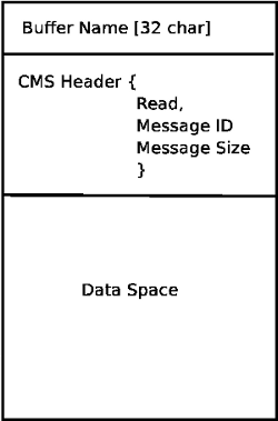
Базовый класс CMS в первую очередь отвечает за создание каналов связи и взаимодействие с операционной системой.
21. Формат файла конфигурации
Конфигурация NML состоит из двух типов форматов строк. Один для буферов, а второй для процессов, которые подключаются к буферам.
21.1. Буферная линия
Исходный формат строки буфера NIST:
-
B name type host size neut RPC# buffer# max_procs key [type specific configs]
-
B - идентифицирует эту строку как конфигурацию буфера.
-
name - это идентификатор буфера.
-
type — описывает тип буфера — SHMEM, LOCMEM, FILEMEM, PHANTOM или GLOBMEM.
-
«хост» — это либо IP-адрес, либо имя хоста для сервера NML
-
size - размер буфера
-
neut - логическое значение, указывающее, закодированы ли данные в буфере в машинно-независимом формате или они в необработанном виде.
-
«RPC#» — устарело — заполнитель сохранен только для обратной совместимости.
-
buffer# — уникальный идентификационный номер, используемый, если сервер управляет несколькими буферами.
-
max_procs - максимальное количество процессов, которым разрешено подключаться к этому буферу.
-
key - числовой идентификатор для буфера общей памяти
21.2. Типизированные конфигурации
Тип буфера подразумевает дополнительные параметры конфигурации, в то время как операционная система хоста исключает определенные комбинации. При попытке преобразовать опубликованную документацию в согласованный формат будет рассмотрен только тип буфера SHMEM.
-
mutex=os_sem - default mode for providing semaphore locking of the buffer memory.
-
mutex=none - Not used
-
mutex=no_interrupts - not applicable on a Linux system
-
mutex=no_switching - not applicable on a Linux system
-
mutex=mao split - Splits the buffer in to half (or more) and allows one process to access part of the buffer whilst a second process is writing to another part.
-
TCP=(port number) - Specifies which network port to use.
-
UDP=(port number) - ditto
-
STCP=(port number) - ditto
-
serialPortDevName=(serial port) - Undocumented.
-
passwd=file_name.pwd - Adds a layer of security to the buffer by requiring each process to provide a password.
-
bsem - NIST documentation implies a key for a blocking semaphore, and if bsem=-1, blocking reads are prevented.
-
queue - Enables queued message passing.
-
ascii - Encode messages in a plain text format
-
disp - Encode messages in a format suitable for display (???)
-
xdr - Encode messages in External Data Representation. (see rpc/xdr.h for details).
-
diag - Enables diagnostics stored in the buffer (timings and byte counts ?)
21.3. Process line
The original NIST format of the process line is:
P name buffer type host ops server timeout master c_num [type specific configs]
-
P - identifies this line as a Process configuration.
-
name - is the identifier of the process.
-
buffer - is one of the buffers defined elsewhere in the config file.
-
type - определяет, является ли этот процесс локальным или удаленным по отношению к буферу.
-
host - указывает, где в сети запущен этот процесс.
-
ops - дает процессу доступ только для чтения, только для записи или для чтения/записи к буферу.
-
server - указывает, будет ли этот процесс запускать сервер для этого буфера.
-
timeout - устанавливает характеристики таймаута для доступа к буферу.
-
master - указывает, отвечает ли этот процесс за создание и уничтожение буфера.
-
c_num - целое число от нуля до (max_procs -1)
21.4. Комментарии к конфигурации
Некоторые из комбинаций конфигурации недействительны, в то время как другие подразумевают определенные ограничения. В системе Linux GLOBMEM устарел, в то время как PHANTOM действительно полезен только на этапе тестирования приложения, как и для FILEMEM. LOCMEM малопригоден для многопроцессорного приложения и предлагает лишь ограниченные преимущества в производительности по сравнению с SHMEM. Это оставляет SHMEM единственным типом буфера для использования с LinuxCNC.
Параметр neut используется только в многопроцессорной системе, где разные (и несовместимые) архитектуры совместно используют блок памяти. Вероятность увидеть систему такого типа за пределами музея или исследовательского учреждения невелика и имеет отношение только к буферам GLOBMEM.
Номер RPC задокументирован как устаревший и сохраняется только по соображениям совместимости.
С уникальным именем буфера наличие числового идентификатора кажется бессмысленным. Необходимо просмотреть код, чтобы определить логику. Точно так же ключевое поле на первый взгляд кажется избыточным и может быть получено из имени буфера.
Цель ограничения количества процессов, которым разрешено подключаться к любому одному буферу, неясна из существующей документации и оригинального исходного кода. Разрешить неопределенным множественным процессам подключаться к буферу реализовать не сложнее.
Типы мьютексов сводятся к одному из двух: по умолчанию «os_sem» или «mao split». Большинство сообщений NML относительно короткие и могут быть скопированы в буфер или из буфера с минимальными задержками, поэтому раздельное чтение не обязательно.
Кодирование данных имеет значение только при передаче удаленному процессу. Использование TCP или UDP подразумевает кодирование XDR. В то время как кодирование ASCII может иметь некоторое применение в диагностике или для передачи данных во встроенную систему, которая не реализует NML.
Протоколы UDP имеют меньше проверок данных и позволяют отбрасывать процент пакетов. TCP более надежен, но немного медленнее.
Если LinuxCNC должен быть подключен к сети, можно надеяться, что она локальная и находится за брандмауэром. Единственная причина разрешить доступ к LinuxCNC через Интернет — удаленная диагностика. Этого можно добиться гораздо более безопасно, используя другие средства, например, веб-интерфейс.
Точное поведение, когда время ожидания установлено равным нулю или отрицательному значению, неясно из документов NIST. Упоминаются только INF и положительные значения. Однако, погребенный в исходном коде rcslib, очевидно, что применимо следующее:
- timeout > 0
-
Blocking access until the timeout interval is reached or access to the buffer is available.
- timeout = 0
-
Access to the buffer is only possible if no other process is reading or writing at the time.
- timeout < 0 or INF
-
Access is blocked until the buffer is available.
22. базовый класс NML
Раскройте списки и взаимосвязь между NML, NMLmsg и классами cms более низкого уровня.
Не путать с NMLmsg, RCS_STAT_MSG или RCS_CMD_MSG.
NML отвечает за синтаксический анализ файла конфигурации, настройку буферов cms и является механизмом маршрутизации сообщений в правильный(е) буфер(ы). Для этого NML создает несколько списков для:
-
буферы cms, созданные или подключенные к ним.
-
процессы и буферы, к которым они подключаются
-
длинный список функций формата для каждого типа сообщения
Этот последний пункт, вероятно, является основной причиной несоответствия libnml/rcslib и NML в целом. Каждое сообщение, передаваемое через NML, требует присоединения определенного объема информации в дополнение к фактическим данным. Для этого последовательно вызываются несколько функций форматирования для сборки фрагментов общего сообщения. Функции формата будут включать NML_TYPE, MSG_TYPE в дополнение к данным, объявленным в производных классах NMLmsg. Изменения в порядке, в котором вызываются функции форматирования, а также передаваемые переменные, нарушат совместимость с rcslib, если с ними что-то не так. Существуют причины для поддержания совместимости с rcslib и веские причины для вмешательства в код. Вопрос в том, какой набор причин превалирует?
22.1. Внутреннее устройство NML
22.1.1. Конструктор NML
NML::NML() анализирует файл конфигурации и сохраняет его в связанном списке для передачи в конструкторы cms в виде отдельных строк. Функция конструктора NML состоит в вызове соответствующего конструктора cms для каждого буфера и ведении списка объектов cms и процессов, связанных с каждым буфером.
Именно с помощью указателей, хранящихся в списках, NML может взаимодействовать с cms, и поэтому Doxygen не может показать реальные отношения.
|
Note
|
Конфиг хранится в памяти до передачи указателя на конкретную строку конструктору cms. Затем конструктор cms снова анализирует строку, чтобы извлечь пару переменных… Было бы разумнее выполнить ВЕСЬ анализ и сохранить переменные в структуре, которая передается конструктору cms. Это устранит обработку строк и уменьшит количество дубликатов кода в cms… |
22.1.2. Чтение/запись NML
Вызовы NML::read и NML::write выполняют схожие задачи в том, что касается обработки сообщения. Единственная реальная разница заключается в направлении потока данных.
Вызов функции чтения сначала получает данные из буфера, затем вызывает format_output(), в то время как функция записи вызывает format_input() перед передачей данных в буфер. Именно в format_xxx() происходит работа по построению или деконструкции сообщения. Список различных функций вызывается по очереди для размещения различных частей заголовка NML (не путать с заголовком cms) в правильном порядке. Последней вызываемой функцией является emcFormat() в emc.cc.
22.1.3. Отношения NMLmsg и NML
NMLmsg — это базовый класс, от которого происходят все классы сообщений. Каждый класс сообщения должен иметь уникальный идентификатор, определенный (и переданный конструктору), а также функцию обновления (*cms). Функция update() будет вызываться функциями чтения/записи NML при вызове модуля форматирования NML — указатель на модуль форматирования будет объявлен в конструкторе NML в какой-то момент. Благодаря связанным спискам, которые создает NML, он может выбирать указатель cms, который передается форматтеру, и, следовательно, какой буфер использовать.
23. Добавление пользовательских команд NML
LinuxCNC довольно крут, но некоторые части нуждаются в правках. Как вы знаете, связь осуществляется через каналы NML, данные, отправляемые через такой канал, являются одним из классов, определенных в emc.hh (реализованных в emc.cc). Если кому-то нужен несуществующий тип сообщения, он должен выполнить следующие шаги, чтобы добавить новый. (Сообщение, которое я добавил в примере, называется EMC_IO_GENERIC (наследует EMC_IO_CMD_MSG (наследует RCS_CMD_MSG)))
-
добавить определение класса EMC_IO_GENERIC в emc2/src/emc/nml_intf/emc.hh
-
add the type define: #define EMC_IO_GENERIC_TYPE \((NMLTYPE) 1605)
-
(я выбрал 1605, потому что он был доступен) в emc2/src/emc/nml_intf/emc.hh
-
-
добавить блок EMC_IO_GENERIC_TYPE в emcFormat в emc2/src/emc/nml_intf/emc.cc
-
добавить блок EMC_IO_GENERIC_TYPE в emc_symbol_lookup в emc2/src/emc/nml_intf/emc.cc
-
добавить функцию EMC_IO_GENERIC::update в emc2/src/emc/nml_intf/emc.cc
Перекомпилируйте, и новое сообщение должно быть там. Следующая часть — отправлять такие сообщения откуда-то, получать их в другом месте и что-то с этим делать.
24. Таблица инструментов и устройство смены инструмента
LinuxCNC взаимодействует с оборудованием смены инструмента и имеет внутреннюю абстракцию смены инструмента. LinuxCNC управляет информацией об инструментах в файле таблицы инструментов.
24.1. Абстракция смены инструмента в LinuxCNC
LinuxCNC поддерживает два типа аппаратных средств смены инструмента, называемых nonrandom и random. Параметр INI [EMCIO]RANDOM_TOOLCHANGER определяет как LinuxCNC будет решать к какому из этих типов оборудования он подключен.
24.1.1. Неслучайная смена инструмента
Устройство автоматической смены инструмента возвращает каждый инструмент в гнездо, из которого он был первоначально взят.
Примерами неслучайного оборудования для смены инструмента являются «ручная» смена инструмента, револьверные головки токарных станков и реечные устройства смены инструмента.
При настройке для неслучайного устройства смены инструмента LinuxCNC не изменяет номер гнезда в файле таблицы инструментов при загрузке и выгрузке инструментов. Внутри LinuxCNC, при смене инструмента информация об инструменте копируется из исходного кармана таблицы инструментов в карман 0 (который представляет шпиндель), заменяя любую информацию об инструменте, которая была там ранее.
|
Note
|
В LinuxCNC, сконфигурированном для неслучайной смены инструмента, инструмент 0 (T0) имеет особое значение: «нет инструмента». T0 может не отображаться в файле таблицы инструментов, и изменение на T0 приведет к тому, что LinuxCNC будет думать, что у него пустой шпиндель. |
24.1.2. Устройства случайной замены инструмента
Устройство случайной смены инструмента меняет инструмент в шпинделе (если есть) на запрошенный инструмент при смене инструмента. Таким образом, карман, в котором находится инструмент, изменяется по мере того, как он вставляется в шпиндель и вынимается из него.
Примером оборудования случайного устройства смены инструмента является устройство смены инструмента карусельного типа.
При настройке случайного устройства смены инструмента LinuxCNC меняет местами номер кармана старого и нового инструмента в файле таблицы инструментов при загрузке инструментов. Внутри LinuxCNC, при смене инструмента информация об инструменте переставляется между исходным гнездом таблицы инструментов и гнездом 0 (которое представляет шпиндель). Таким образом, после смены инструмента карман 0 в таблице инструментов содержит информацию об инструменте для нового инструмента, а карман, из которого был получен новый инструмент, содержит информацию об инструменте для старого инструмента (инструмент, который был в шпинделе до смены инструмента) если такой есть.
|
Note
|
Если LinuxCNC настроен на случайную смену инструмента, инструмент 0 (T0) не имеет специального значения. Он обрабатывается точно так же, как и любой другой инструмент в таблице инструментов. Обычно T0 используется для обозначения «отсутствия инструмента» (т. е. инструмента с нулевым TLO), чтобы при необходимости шпиндель мог быть удобно разгружен. |
24.2. Таблица инструментов
LinuxCNC отслеживает инструменты в файле tool table. В таблице инструментов записывается следующая информация для каждого инструмента:
- номер инструмента
-
Целое число, которое однозначно идентифицирует этот инструмент. Номера инструментов обрабатываются LinuxCNC по-разному при настройке случайных и неслучайных устройств смены инструмента:
-
Когда LinuxCNC настроен для неслучайного устройства смены инструмента, это число должно быть положительным. T0 подвергается специальной обработке и не может отображаться в таблице инструментов.
-
Когда LinuxCNC настроен для случайного устройства смены инструмента, это число должно быть неотрицательным. T0 допускается в таблице инструментов и обычно используется для обозначения отсутствия инструмента, то есть пустого кармана.
-
- номер гнезда
-
Целое число, идентифицирующее гнездо или паз в оборудовании устройства смены инструмента, в котором находится инструмент. Номера карманов обрабатываются LinuxCNC по-разному при настройке случайных и неслучайных устройств смены инструмента:
-
Когда LinuxCNC сконфигурирован для неслучайного устройства смены инструмента, номер гнезда в файле инструмента может быть любым положительным целым числом (ячейка 0 не допускается). LinuxCNC молча уплотняет номера гнезд при загрузке файла инструмента, поэтому может быть разница между номерами гнезд в файле инструмента и внутренними номерами гнезд, используемыми LinuxCNC с неслучайным устройством смены инструмента.
-
Когда LinuxCNC настроен для случайного устройства смены инструмента, номера карманов в файле инструмента должны быть в диапазоне от 0 до 1000 включительно. Гнезда 1-1000 находятся в устройстве смены инструмента, гнездо 0 - это шпиндель.
-
- diameter
-
Диаметр инструмента в единицах измерения станка.
- смещение длины инструмента
-
Коррекция длины инструмента (также называемая TLO), до 9 осей, в единицах измерения станка. Оси, у которых нет указанного TLO, получают 0.
24.3. G-коды, влияющие на инструменты
G-коды, которые используют или влияют на информацию об инструменте:
24.3.1. Txxx
Указывает оборудованию смены инструмента подготовиться к переключению на указанный инструмент xxx.
Обрабатывается Interp::convert_tool_select().
-
Станку предлагается подготовиться к переключению на выбранный инструмент, путем вызова Canon функции
SELECT_TOOL()с номером запрошенного инструмента.-
(saicanon) No-op.
-
(emccanon) Создает сообщение
EMC_TOOL_PREPAREс запрошенным номером кармана и отправляет его в Task, который отправляет его в IO. IO получает сообщение и просит HAL подготовить карман, установивiocontrol.0.tool-prep-pocket,iocontrol.0.tool-prep-numberиiocontrol.0.tool-prepare. Затем IO повторно вызываетread_tool_inputs()для опроса вывода HALiocontrol.0.tool-prepared, который сигнализирует от оборудования смены инструмента через HAL IO, что запрошенная подготовка инструмента завершена. Когда этот вывод становится True, IO устанавливаетemcioStatus.tool.pocketPreppedна номер кармана запрошенного инструмента.
-
-
Вернувшись в интерпретацию,
settings->selected_pocketприсваивается индекс tooldata запрошенного инструмента xxx.
|
Note
|
Устаревшие имена selected_pocket и current_pocket на самом деле ссылаются на последовательный индекс данных инструмента для элементов инструмента, загруженных из таблицы инструментов ([EMCIO]TOOL_TABLE) или через базу данных инструментов ([EMCIO]DB_PROGRAM). |
24.3.2. M6
Сообщает устройству смены инструмента переключиться на текущий выбранный инструмент (выбранный предыдущей командой Txxx).
Обрабатывается Interp::convert_tool_change().
-
Станку предлагается перейти на выбранный инструмент, путем вызова Canon функции
CHANGE_TOOL()сsettings->selected_pocket(индекс данных инструмента).-
(saicanon) Устанавливает sai’s
_active_slotв переданный номер кармана. Информация об инструменте копируется из выбранного кармана таблицы инструментов (т. е. из sai’s_tools[_active_slot]) на шпиндель (он же sai’s_tools[0]). -
(emccanon) Отправляет сообщение
EMC_TOOL_LOADв Task, которое отправляет его в IO. IO устанавливаетemcioStatus.tool.toolInSpindleна номер инструмента в гнезде, указанномemcioStatus.tool.pocketPrepped(устанавливаетсяTxxx, также известным какSELECT_TOOL()). Затем он запрашивает, чтобы оборудование смены инструмента выполнило смену инструмента, установив для контакта HALiocontrol.0.tool-changeзначение True. Позжеread_tool_inputs()IO обнаружит, что контакт HALiocontrol.0.tool_changedбыл установлен в True, указывая на то, что устройство смены инструмента завершило смену инструмента. Когда это происходит, он вызываетload_tool()для обновления состояния станка.-
load_tool()с конфигурацией устройства неслучайной смены инструмента копирует информацию об инструменте из выбранного гнезда в шпиндель (карман 0). -
load_tool()с конфигурацией устройства случайной смены инструмента меняет местами информацию об инструменте между гнездом 0 (шпиндель) и выбранным гнездом, затем сохраняет таблицу инструментов.
-
-
-
Вернувшись в интерпретатор,
settings->current_pocketназначается новый индекс tooldata изsettings->selected_pocket(устанавливаетсяTxxx). Соответствующие пронумерованные параметры (#5400-#5413) обновляются новой информацией об инструменте из гнезда 0 (шпиндель).
24.3.3. G43/G43.1/G49
Применить коррекцию длины инструмента. G43 использует TLO загруженного в данный момент инструмента или указанного инструмента, если H-слово задано в блоке. G43.1 получает TLO из осевых слов в блоке. G49 отменяет TLO (использует 0 для смещения для всех осей).
Обрабатывается Interp::convert_tool_length_offset().
-
Он начинается со сборки
EmcPose, содержащего для использования смещения 9-и осей. ДляG43.1эти коррекции инструмента берутся из слов осей в текущем кадре. ДляG43эти коррекции исходят от текущего инструмента (инструмент в гнезде 0) или от инструмента, указанного H-словом в блоке. Для G49 все смещения равны 0. -
Смещения передаются Canon функции
USE_TOOL_LENGTH_OFFSET().-
(saicanon) Записывает TLO в
_tool_offset. -
(emccanon) Создает сообщение
EMC_TRAJ_SET_OFFSET, содержащее смещения, и отправляет его в Task. Task копирует смещения вemcStatus->task.toolOffsetи отправляет их в Motion с помощью командыEMCMOT_SET_OFFSET. Движение копирует смещения вemcmotStatus->tool_offset, где оно используется для смещения будущих перемещений.
-
-
Вернувшись в интерпретацию, смещения записываются в
settings->tool_offset. Эффективное гнездо записывается вsettings->tool_offset_index, хотя это значение никогда не используется.
24.3.4. G10 L1/L10/L11
Изменяет таблицу инструментов.
Обрабатывается Interp::convert_setup_tool().
-
Picks the tool number out of the P-word in the block and finds the pocket for that tool:
-
With a nonrandom toolchanger config this is always the pocket number in the toolchanger (even when the tool is in the spindle).
-
With a random toolchanger config, if the tool is currently loaded it uses pocket 0 (pocket 0 means "the spindle"), and if the tool is not loaded it uses the pocket number in the tool changer. (This difference is important.)
-
-
Figures out what the new offsets should be.
-
The new tool information (diameter, offsets, angles, and orientation), along with the tool number and pocket number, are passed to the Canon call SET_TOOL_TABLE_ENTRY().
-
(saicanon) Copy the new tool information to the specified pocket (in sai’s internal tool table,
_tools). -
(emccanon) Build an
EMC_TOOL_SET_OFFSETmessage with the new tool information, and send it to Task, which passes it to IO. IO updates the specified pocket in its internal copy of the tool table (emcioStatus.tool.toolTable), and if the specified tool is currently loaded (it is compared toemcioStatus.tool.toolInSpindle) then the new tool information is copied to pocket 0 (the spindle) as well. (FIXME: that’s a buglet, should only be copied on nonrandom machines.) Finally IO saves the new tool table.
-
-
Back in interp, if the modified tool is currently loaded in the spindle, and if the machine is a non-random toolchanger, then the new tool information is copied from the tool’s home pocket to pocket 0 (the spindle) in interp’s copy of the tool table,
settings->tool_table. (This copy is not needed on random tool changer machines because there, tools don’t have a home pocket and instead we just updated the tool in pocket 0 directly.). The relevant numbered parameters (#5400-#5413) are updated from the tool information in the spindle (by copying the information from interp’ssettings->tool_tabletosettings->parameters). (FIXME: this is a buglet, the params should only be updated if it was the current tool that was modified). -
If the modified tool is currently loaded in the spindle, and if the config is for a nonrandom toolchanger, then the new tool information is written to the tool table’s pocket 0 as well, via a second call to SET_TOOL_TABLE_ENTRY(). (This second tool-table update is not needed on random toolchanger machines because there, tools don’t have a home pocket and instead we just updated the tool in pocket 0 directly.)
24.3.5. M61
Set current tool number. This switches LinuxCNC’s internal representation of which tool is in the spindle, without actually moving the toolchanger or swapping any tools.
Обрабатывается Interp::convert_tool_change().
Canon: CHANGE_TOOL_NUMBER()
settings->current_pocket is assigned the tooldata index currently holding the tool specified by the Q-word argument.
24.3.6. G41/G41.1/G42/G42.1
Enable cutter radius compensation (usually called cutter comp).
Handled by Interp::convert_cutter_compensation_on().
No Canon call, cutter comp happens in the interpreter. Uses the tool table in the expected way: if a D-word tool number is supplied it looks up the pocket number of the specified tool number in the table, and if no D-word is supplied it uses pocket 0 (the spindle).
24.3.7. G40
Cancel cutter radius compensation.
Handled by Interp::convert_cutter_compensation_off().
No Canon call, cutter comp happens in the interpreter. Does not use the tool table.
24.4. Internal state variables
This is not an exhaustive list! Tool information is spread through out LinuxCNC.
24.4.1. IO
emcioStatus is of type EMC_IO_STAT
- emcioStatus.tool.pocketPrepped
-
When IO gets the signal from HAL that the toolchanger prep is complete (after a
Txxxcommand), this variable is set to the pocket of the requested tool. When IO gets the signal from HAL that the tool change itself is complete (after anM6command), this variable gets reset to -1. - emcioStatus.tool.toolInSpindle
-
Tool number of the tool currently installed in the spindle. Exported on the HAL pin
iocontrol.0.tool-number(s32). - emcioStatus.tool.toolTable[]
-
An array of
CANON_TOOL_TABLEstructures,CANON_POCKETS_MAXlong. Loaded from the tool table file at startup and maintained there after. Index 0 is the spindle, indexes 1-(CANON_POCKETS_MAX-1) are the pockets in the toolchanger. This is a complete copy of the tool information, maintained separately from Interp’ssettings.tool_table.
24.4.2. interp
settings is of type settings, defined as struct setup_struct in src/emc/rs274ngc/interp_internal.hh.
- settings.selected_pocket
-
Tooldata index of the tool most recently selected by
Txxx. - settings.current_pocket
-
Original tooldata index of the tool currently in the spindle. In other words: which tooldata index the tool that’s currently in the spindle was loaded from.
- settings.tool_table[]
-
An array of tool information. The index into the array is the "pocket number" (aka "slot number"). Pocket 0 is the spindle, pockets 1 through (CANON_POCKETS_MAX-1) are the pockets of the toolchanger.
- settings.tool_offset_index
-
Unused. FIXME: Should probably be removed.
- settings.toolchange_flag
-
Interp sets this to true when calling Canon’s CHANGE_TOOL() function. It is checked in
Interp::convert_tool_length_offset()to decide which tooldata index to use for G43 (with no H-word):settings->current_pocketif the tool change is still in progress, tooldata index 0 (the spindle) if the tool change is complete. - settings.random_toolchanger
-
Set from the INI variable
[EMCIO]RANDOM_TOOLCHANGERat startup. Controls various tool table handling logic. (IO also reads this INI variable and changes its behavior based on it. For example, when saving the tool table, random toolchanger save the tool in the spindle (pocket 0), but non-random toolchanger save each tool in its "home pocket".) - settings.tool_offset
-
This is an
EmcPosevariable.-
Used to compute position in various places.
-
Отправляется в Motion через сообщение
EMCMOT_SET_OFFSET. Все, что движение делает со смещениями, — это экспортирует их на контакты HALmotion.0.tooloffset.[xyzabcuvw]. FIXME: экспортируйте их куда-нибудь ближе к таблице инструментов (вероятно, io или interp) и удалите сообщение EMCMOT_SET_OFFSET.
-
- settings.pockets_max
-
Used interchangeably with
CANON_POCKETS_MAX(a #defined constant, set to 1000 as of April 2020). FIXME: This settings variable is not currently useful and should probably be removed. - settings.tool_table
-
This is an array of
CANON_TOOL_TABLEstructures (defined insrc/emc/nml_intf/emctool.h), withCANON_POCKETS_MAXentries. Indexed by "pocket number", aka "slot number". Index 0 is the spindle, indexes 1 to (CANON_POCKETS_MAX-1) are the pockets in the tool changer. On a random toolchanger pocket numbers are meaningful. On a nonrandom toolchanger pockets are meaningless; the pocket numbers in the tool table file are ignored and tools are assigned totool_tableslots sequentially. - settings.tool_change_at_g30
- settings.tool_change_quill_up
- settings.tool_change_with_spindle_on
-
These are set from INI variables in the
[EMCIO]section, and determine how tool changes are performed.
25. Reckoning of joints and axes
25.1. In the status buffer
The status buffer is used by Task and the UIs.
FIXME: axis_mask and axes overspecify the number of axes
-
status.motion.traj.axis_mask -
A bitmask with a "1" for the axes that are present and a "0" for the axes that are not present. X is bit 0 with value 20 = 1 if set, Y is bit 1 with value 21 = 2, Z is bit 2 with value 4, etc. For example, a machine with X and Z axes would have an
axis_maskof 0x5, an XYZ machine would have 0x7, and an XYZB machine would have anaxis_maskof 0x17. -
status.motion.traj.axes(removed) -
This value was removed in LinuxCNC version 2.9. Use
axis_maskinstead. -
status.motion.traj.joints -
A count of the number of joints the machine has. A normal lathe has 2 joints; one driving the X axis and one driving the Z axis. An XYYZ gantry mill has 4 joints: one driving X, one driving one side of the Y, one driving the other side of the Y, and one driving Z. An XYZA mill also has 4 joints.
-
status.motion.axis[EMCMOT_MAX_AXIS] -
An array of
EMCMOT_MAX_AXISaxis structures.axis[n]is valid if(axis_mask & (1 << n))is True. If(axis_mask & (1 << n))is False, thenaxis[n]does not exist on this machine and must be ignored. -
status.motion.joint[EMCMOT_MAX_JOINTS] -
An array of
EMCMOT_MAX_JOINTSjoint structures.joint[0]throughjoint[joints-1]are valid, the others do not exist on this machine and must be ignored.
Things are not this way currently in the joints-axes branch, but deviations from this design are considered bugs. For an example of such a bug, see the treatment of axes in src/emc/ini/initraj.cc:loadTraj(). There are undoubtedly more, and I need your help to find them and fix them.
25.2. In Motion
Компонент реального времени контроллера движения сначала получает количество соединений из параметра времени загрузки num_joints. Это определяет, сколько сочленений заслуживающих контактов HAL будет создано при запуске.
Motion’s number of joints can be changed at runtime using the EMCMOT_SET_NUM_JOINTS command from Task.
Контроллер движения всегда работает по осям EMCMOT_MAX_AXIS. Он всегда создает девять наборов контактов axis.*.*.