
Vismach is a set of Python functions that can be used to create and animate models of machines.
This chapter is about the Qt embedded version of Vismach, also see: https://sa-cnc.com/linuxcnc-vismach/ .
1. Introduction
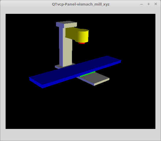
Vismach displays the model in a 3D viewport and the model parts are animated as the values of associated HAL pins change.
The Vismach 3D viewport view can be manipulated as follows:
-
zoom by scroll wheel
-
pan by middle button drag
-
rotate by right-button drag
-
tilt by left button drag
A Vismach model takes the form of a Python script and can use standard Python syntax.
This means that there is more than one way to lay out the script, but in the examples given in this document the simplest and most basic of them will be used.
The basic sequence in creating the Vismach model is:
-
Create the parts
-
Define how they move
-
Assemble into movement groups
2. Hierarchy of Machine Design
The model follows logical tree design.
Picture the tree, with root/trunk, branches and smaller branches off it. If you move the larger branch, smaller branches will move with it, but if you move the smaller branch, the larger will not.
Machine design follows that conceptual design.
Taking the mill shown in the 3D Viewport picture above for example:
-
If you move X, it can move on its own,
-
but if you move Y, it will also move X assembly, as it is attached to Y assembly.
So for this machine, the tree looks like this:
model
  |
  |---frame
  |     |
  |     |---base
  |     |
  |     |---column
  |     |
  |     |---top
  |
  |---yassembly
  |      |
  |      |---xassembly
  |      |      |
  |      |      |---xbase
  |      |      |
  |      |      |---work
  |      |
  |      |---ybase
  |
  |---zassembly
          |
          |---zframe
          |     |
          |     |---zbody
          |     |
          |     |---spindle
          |
          |---toolassembly
                    |
                    |---cat30
                    |
                    |---tool
                         |
                         |---tooltip
                         |
                         |---(tool cylinder function)
As you can see, the lowest parts must exist first before those can be grouped with others into an assembly. So you build upwards from lowest point in tree and assemble them together.
The same is applicable for any design of machine: look at the machine arm example and you will see that it starts with the tip and adds to the larger part of the arm, then it finally groups with the base.
3. Start the script
It is useful for testing to include the #!/usr/bin/env python3 shebang line to _allow the file to be executed directly from the command line.
The first thing to do is to import the required libraries.
#!/usr/bin/env python3

import hal
import math
import sys

from qtvcp.lib.qt_vismach.qt_vismach import *
4. HAL pins.
Originally the vismach library required creating a component and connecting HAL pins to control the simulation.
qt_vismach can read the HAL system pins directly or if you wish, to use separate HAL pins that you must define in a HAL component:
c = hal.component("samplegui")
c.newpin("joint0", hal.HAL_FLOAT, hal.HAL_IN)
c.newpin("joint1", hal.HAL_FLOAT, hal.HAL_IN)
c.ready()
You can select between the two options in the functions that take these entries:
hal_comp-
The HAL component Object or None.
In QtVCP if you are reading system pins directly, then the component argument is set toNone. hal_pin-
The name of the BIT HAL IN pin that will change the color.
If hal_comp is None then this must be the full name of a system pin otherwise this is the pin name excluding the component name.
5. Creating Parts
5.1. Import STL or OBJ Files
It is probably easiest to:
-
create geometry in a CAD package
-
import into the model script using the
AsciiSTL()orAsciiOBJ()functions.
Both functions can take one of two named arguments, either a filename or data:
part = AsciiSTL(filename="path/to/file.stl")
part = AsciiSTL(data="solid part1 facet normal ...")
part = AsciiOBJ(filename="path/to/file.obj")
part = AsciiOBJ(data="v 0.123 0.234 0.345 1.0 ...")-
STL model parts are added to the Vismach space in the same locations as they were created in the STL or OBJ space, i.e. ideally with a rotational point at their origin.
|
Note
|
It is much easier to move while building if the origin of the model is at a rotational pivot point. |
5.2. Build from Geometric Primitives
Alternatively parts can be created inside the model script from a range of shape primitives.
assembly = collction([part1,part2,part3])-
Collection is a general container of related parts
Many shapes are created at the origin and need to be moved to the required location after creation.
cylinder = CylinderX(x1, r1, x2, r2)cylinder = CylinderY(y1, r1, y2, r2)cylinder = CylinderZ(z1, r1, z2, r2)-
Creates a (optionally tapered) cylinder on the given axis with the given radii at the given points on the axis.
sphere = Sphere(x, y, z, r)-
Creates a sphere of radius r at (x,y,z).
triangle = TriangleXY(x1, y1, x2, y2, x3, y3, z1, z2)triangle = TriangleXZ(x1, z1, x2, z2, x3, z3, y1, y2)triangle = TriangleYZ(y1, z1, y2, z2, y3, z3, x1, x2)-
Creates a triangular plate between planes defined by the last two values parallel to the specified plane, with vertices given by the three coordinate pairs.
arc = ArcX(x1, x2, r1, r2, a1, a2)-
Create an arc shape.
box = Box(x1, y1, z1, x2, y2, z2)-
Creates a rectangular prism with opposite corners at the specified positions and edges parallel to the XYZ axes.
box = BoxCentered(xw, yw, zw)-
Creates an xw by yw by zw box centred on the origin.
box = BoxCenteredXY(xw, yw, z)-
Creates a box ground on WY plane of width xw / yw and height z.
Composite parts may be created by assembling these primitives either at creation time or subsequently:
part1 = Collection([Sphere(100,100,100,50), CylinderX(100,40,150,30)])
part2 = Box(50,40,75,100,75,100)
part3 = Collection([part2, TriangleXY(10,10,20,10,15,20,100,101)])
part4 = Collection([part1, part2])
6. Moving Model Parts
Parts may need to be moved in the Vismach space to assemble the model. The origin does not move - Translate() and Rotate() move the Collection as you add parts, relative to a stationary origin.
6.1. Translating Model parts
part1 = Translate([part1], x, y, z)-
Move part1 the specified distances in x, y and z.
6.2. Rotating Model Parts
part1 = Rotate([part1], theta, x, y, z)-
Rotate the part by angle theta [degrees] about an axis between the origin and x, y, z.
7. Animating Parts
To animate the model controlled by the values of HAL pins there are four functions: HalTranslate, HalRotate, HalToolCylinder and HalToolTriangle.
For parts to move inside an assembly they need to have their HAL motions defined before being assembled with the "Collection" command.
The rotation axis and translation vector move with the part:
-
as it is moved by the Vismach script during model assembly, or
-
as it moves in response to the HAL pins as the model is animated.
7.1. HalTranslate
part = HalTranslate([part], hal_comp, hal_pin, xs, ys, zs)-
part-
A collection or part.
It can be pre-created earlier in the script, or could be created at this point if preferred, e.g.,`part1 = HalTranslate([Box(....)], ...)`. + hal_comp-
The HAL component is the next argument.
In QtVCP if you are reading system pins directly then the component argument is set toNone. hal_pin-
The name of the HAL pin that will animate the motion.
This needs to match an existing HAL pin that describes the joint position such as:"joint.2.pos-fb"Otherwise the component instance would be specified and the pin name of that component would be specified.
xs, ys, zs-
The X, Y, Z scales.
For a Cartesian machine created at 1:1 scale this would typically be1,0,0for a motion in the positive X direction.
However if the STL file happened to be in cm and the machine was in inches, this could be fixed at this point by using 0.3937 ( = 1 cm/1 inch = 1 cm /2.54 cm ) as the scale.
7.2. HalRotate
part = HalRotate([part], hal_comp, hal_pin, angle_scale, x, y, z)-
This command is similar in its operation to
HalTranslate, except that it is typically necessary to move the part to the origin first to define the axis.x, y, z-
Defines the axis of rotation from the origin the point of coordinates (x,y,z).
When the part is moved back away from the origin to its correct location, the axis of rotation can be considered to remain "embedded" in the part. angle_scale-
Rotation angles are in degrees, so for a rotary joint with a 0-1 scaling you would need to use an angle scale of 360.
7.3. HalToolCylinder
tool = HalToolCylinder()-
Make a cylinder to represent a cylindrical mill tool, based on the tool table and current loaded tool.
tool = HalToolCylinder()
toolshape = Color([1, .5, .5, .5],[tool])

# or more compact:
toolshape = Color([1, .5, .5, .5], [HalToolCylinder()])
7.4. HalToolTriangle
tool = HalToolTriangle()-
Make a triangle to represent a triangular lathe tool, based on the tool table and current loaded tool.
tool = HalToolTriangle()
toolshape = Color([1, 1, 0, 1],[tool])

# or more compact:
toolshape = Color([1, 1, 0, 1],[HalToolTriangle()])
7.5. HAL Adjustable Primitives
All shape primitives can have HAL pin names substituted for coordinates.
Either by adding the component object as the first variable and substituting the pinname string for a coordinate, or
by substituting the full component/pinname string for a coordinate.
This example creates a rectangular prism with opposite corners at the specified positions and edges parallel to the XYZ axes.
The Z start coordinate will be controlled by the HAL pin Zstart.
box = Box(component, x1, y1, 'Zstart', x2, y2, z2)
box = Box(x1, y1, 'componentName.Zstart', x2, y2, z2)
8. Assembling the model
In order for parts to move together they need to be assembled with the Collection() command.
It is important to assemble the parts and define their motions in the correct sequence.
For example to create a moving head milling machine with a rotating spindle and an animated draw bar you would:
-
Create the head main body.
-
Create the spindle at the origin.
-
Define the rotation.
-
Move the head to the spindle or spindle to the head.
-
Create the draw bar.
-
Define the motion of the draw bar.
-
Assemble the three parts into a head assembly.
-
Define the motion of the head assembly.
In this example the spindle rotation is indicated by rotation of a set of drive dogs:
#Drive dogs
dogs = Box(-6,-3,94,6,3,100)
dogs = Color([1,1,1,1],[dogs])
dogs = HalRotate([dogs],c,"spindle",360,0,0,1)
dogs = Translate([dogs],-1,49,0)

#Drawbar
draw = CylinderZ(120,3,125,3)
draw = Color([1,0,.5,1],[draw])
draw = Translate([draw],-1,49,0)
draw = HalTranslate([draw],c,"drawbar",0,0,1)

# head/spindle
head = AsciiSTL(filename="./head.stl")
head = Color([0.3,0.3,0.3,1],[head])
head = Translate([head],0,0,4)
head = Collection([head, tool, dogs, draw])
head = HalTranslate([head],c,"Z",0,0,0.1)

# base
base = AsciiSTL(filename="./base.stl")
base = Color([0.5,0.5,0.5,1],[base])
# mount head on it
base = Collection([head, base])
Finally a single collection of all the machine parts, floor and work (if any) needs to be created.
For a serial machine each new part will be added to the collection of the previous part.
For a parallel machine there may be several "base" parts.
Thus, for example, in scaragui.py link3 is added to link2, link2 to link1 and link1 to link0, so the final model is created by:
model = Collection([link0, floor, table])Whereas a VMC model with separate parts moving on the base might have
model = Collection([base, saddle, head, carousel])9. Other functions
9.1. Color
Sets the display color of the part.
part = Color([_colorspec_], [_part_])-
Note that unlike the other functions, the part definition comes second in this case.
_colorspec_-
Three (0-1.0) RGB values and opacity. [R,G,B,A]
For example [1.0,0,0,0.5] for a 50% opacity red.
9.2. HALColorFlip
Sets the display color of the part based on a designated HAL bit pin state.
part = HALColorFlip([_colorspec_], [_colorspec_], [_part_], hal_comp, hal_pin)-
Note that unlike the other functions, the part definition comes second in this case.
_colorspec_-
Three (0-1.0) RGB values and opacity.
For example [1.0,0,0,0.5] for a 50% opacity red. hal_comp-
The HAL component Object or None.
In QtVCP if you are reading system pins directly, then the component argument is set toNone. hal_pin-
The name of the BIT HAL IN pin that will change the color.
if hal_comp is None then this must be the full name of a system pin other wise this is the pin name excluding the component name.
9.3. HALColorRGB
Sets the display color of the part based on a designated HAL U32 pin value.
The color is decoded from the U32 value. each color is a 0-255 decimal value (shown here in hex)
red = 0xXXXXXXRR
green = 0xXXXXGGXX
blue = 0xXXBBXXXX
combined as 0xXXBBGGRR
part = HALColorRGB([_part_], hal_comp, hal_pin, alpha=1.0)-
hal_comp-
The HAL component Object or None.
In QtVCP if you are reading system pins directly, then the component argument is set toNone. hal_pin-
The name of the U32 HAL IN pin that will change the color.
if hal_comp is None then this must be the full name of a system pin other wise this is the pin name excluding the component name. alpha=-
Sets the opacity. (0-1.0)
9.4. Heads Up Display
Creates a heads-up display in the Vismach GUI to display items such as axis positions, titles, or messages.
myhud = Hud()
myhud = Hud()
myhud.show("Mill_XYZ")`
9.5. HAL Heads Up Display
A more advanced version of the Hud that allows HAL pins to be displayed:
myhud = HalHud()
myhud = HalHud()
myhud.display_on_right()
myhud.set_background_color(0,.1,.2,0)
myHud.set_text_color(1,1,1)
myhud.show_top("Mill_XYZ")
myhud.show_top("------------")
myhud.add_pin('axis-x: ',"{:10.4f}","axis.x.pos-cmd")
myhud.add_pin('axis-y: ',"{:10.4f}","axis.y.pos-cmd")
myhud.add_pin('axis-z: ',"{:10.4f}","axis.z.pos-cmd")
myhud.show("-------------")
Some of the available HalHUD function:
-
set_background_color(red, green, blue, alpha)
-
add_pin(text, format, pinname)
-
set_text_color(red, green, blue)
9.6. HideCollection
HideCollection is a container that uses a HAL pin to control display of the contained parts. +
A logic high on the HAL pin will hide the contained parts.
comp.newpin("hide-chuck", hal.HAL_BIT, hal.HAL_IN)
# <snip make a machine with an A axis chuck assembly>
chuckassembly = HideCollection([chuckassembly],comp,'hide-chuck')
# also can be used like this
chuckassembly = HideCollection([chuckassembly],None,'myvismach.hide-chuck')
9.7. Plot Color Based on Motion Type
If you wish to plot different colors for different motions you need to add some more Python code.
Add this at the top of the file:
from qtvcp.core import Status
STATUS = Status()
and this to the Window class:
STATUS.connect('motion-type-changed', lambda w, data: v.choosePlotColor(data))

# uncomment to change feed color and to see all colors printed to the terminal
#v.setColorsAttribute('FEED',(0,1,0))
#print(v.colors)
You can set DEFAULT, FEED, TRAVERSE, ARC, PROBE, ROTARYINDEX, TOOLCHANGE colors with setColorsAttribute().
9.8. Capture
-
tooltip = Capture()
Think of this as an invisible part that needs to be attached to the tooltip to track the position and orientation of the tool coordinate system. It is actually a transformation matrix that is constantly updated as the model moves. -
work = Capture()
Same as above but attached to the work table to track the work coordinate system.
9.9. main
This is the command that makes it all happen, creates the display, etc. if invoked directly from Python.
Usually this file is imported by QtVCP and the window() object is instantiated and embedded into another screen.
main(model, tooltip, work, size=10, hud=myhud, rotation_vectors=None, lat=0, lon=0)-
_model_-
Should be a collection that contains all the machine parts.
_tooltip_and_work_-
Need to be created by
Capture()to draw the backplot which is basically the tooltip position drawn in the work coordinate system. Seemill_xyz.pyfor an example of how to connect the tool tip to a tool and the tool to the model. _size_-
Sets the extent of the volume visualized in the initial view.
_hud_-
refers to a head-up display.
_rotation_vectors_or_lat, lon_-
Can be used to set the original viewpoint. It is advisable to do as the default initial viewpoint is rather unhelpful from immediately overhead.
10. Tips
Create an axes origin marker to be able to see parts relative to it, for construction purposes. You can remove it when you are done.
# build axis origin markers
X = CylinderX(-500,1,500,1)
X = Color([1, 0, 0, 1], [X])
Y = CylinderY(-500,1,500,1)
Y = Color([0, 1, 0, 1], [Y])
Z = CylinderZ(-500,1,500,1)
Z = Color([0, 0, 1, 1], [Z])
origin = Collection([X,Y,Z])
Add it to the Window class Collection so it is never moved from the origin.
v.model = Collection([origin, model, world])Start from the cutting tip and work your way back. Add each collection to the model at the origin and run the script to confirm the location, then rotate/translate and run the script to confirm again.
11. Basic structure of a QtVismach script
# imports
import hal
from qtvcp.lib.qt_vismach.qt_vismach import *

# import Status for motion type messages
from qtvcp.core import Status
STATUS = Status()

# create HAL pins here if needed
#c = hal.component("samplegui")
#c.newpin("joint0", hal.HAL_FLOAT, hal.HAL_IN)

# create the floor, tool and work
floor = Box(-50, -50, -3, 50, 50, 0)
work = Capture()
tooltip = Capture()

# Build and assemble the model
part1 = Collection([Box(-6,-3,94,6,3,100)])
part1 = Color([1,1,1,1],[part1])
part1 = HalRotate([part1],None,"joint.0.pos-fb",360,0,0,1)
part1 = Translate([dogs],-1,49,0)

# create a top-level model
model = Collection([base, saddle, head, carousel])

# we want to either embed into qtvcp or display directly with PyQt5
# so build a window to display the model

class Window(QWidget):

    def __init__(self):
        super(Window, self).__init__()
        self.glWidget = GLWidget()
        v = self.glWidget
        v.set_latitudelimits(-180, 180)

        world = Capture()

        # uncomment if there is a HUD
        # HUD needs to know where to draw
        #v.hud = myhud
        #v.hud.app = v

        # update plot color based on motion type
        STATUS.connect('motion-type-changed', lambda w, data: v.choosePlotColor(data))

        # uncomment to change feed color
        #v.setColorsAttribute('FEED',(0,1,0))
        # and to see all colors printed to the terminal
        #print(v.colors)

        v.model = Collection([model, world])
        size = 600
        v.distance = size * 3
        v.near = size * 0.01
        v.far = size * 10.0
        v.tool2view = tooltip
        v.world2view = world
        v.work2view = work

        mainLayout = QHBoxLayout()
        mainLayout.addWidget(self.glWidget)
        self.setLayout(mainLayout)

# if you call this file directly from python3, it will display a PyQt5 window
# good for confirming the parts of the assembly.

if __name__ == '__main__':
    main(model, tooltip, work, size=600, hud=None, lat=-75, lon=215)