
Bei all diesen Beispielen wird davon ausgegangen, dass Sie mit einer stepconf-basierten Konfiguration beginnen und zwei Threads base-thread und servo-thread haben. Der StepConf-Assistent erstellt eine leere Datei custom.hal und eine Datei custom_postgui.hal. Die Datei custom.hal wird nach der Konfigurations-HAL-Datei geladen und die Datei custom_postgui.hal wird geladen, nachdem die GUI geladen wurde.
1. Verbinden von zwei Ausgängen
Um zwei Ausgänge mit einem Eingang zu verbinden, können Sie die Komponente or2 verwenden. Die or2-Komponente funktioniert folgendermaßen: Wenn einer der beiden Eingänge von or2 eingeschaltet ist, dann ist der or2-Ausgang eingeschaltet. Wenn keiner der beiden Eingänge von or2 eingeschaltet ist, dann ist der or2-Ausgang ausgeschaltet.
Zum Beispiel, um zwei PyVCP-Tasten zu haben, die beide an eine LED angeschlossen sind.
<pyvcp>
  <button>
    <halpin>"button-1"</halpin>
    <text>"Button 1"</text>
  </button>

  <button>
    <halpin>"button-2"</halpin>
    <text>"Button 2"</text>
  </button>

  <led>
    <halpin>"led-1"</halpin>
    <size>50</size>
    <on_color>"green"</on_color>
    <off_color>"red"</off_color>
  </led>
</pyvcp>
loadrt or2
addf or2.0 servo-thread
net button-1 or2.0.in0 <= pyvcp.button-1
net button-2 or2.0.in1 <= pyvcp.button-2
net led-1 pyvcp.led-1 <= or2.0.out
Wenn Sie dieses Beispiel in einem mit dem StepConf-Assistenten erstellten Achsen-Simulator ausführen, können Sie ein Terminal öffnen und die mit loadrt or2 erstellten Pins sehen, indem Sie halcmd show pin or2 in das Terminal eingeben.
halcmd in der UNIX-Befehlszeile, um die mit dem Modul or2 bereitgestellten Pins anzuzeigen.$ halcmd show pin or2
Component Pins:
Owner Type Dir Value Name
22 bit IN FALSE or2.0.in0 <== button-1
22 bit IN FALSE or2.0.in1 <== button-2
22 bit OUT FALSE or2.0.out ==> led-1
Aus dem HAL-Befehl show pin or2 geht hervor, dass der Pin button-1 mit dem Pin or2.0.in0 verbunden ist, und aus dem Richtungspfeil geht hervor, dass der Button ein Ausgang und der or2.0.in0 ein Eingang ist. Der Ausgang von or2 geht an den Eingang der LED.
2. Manueller Werkzeugwechsel
In diesem Beispiel wird davon ausgegangen, dass Sie Ihre eigene Konfiguration erstellen und das Fenster HAL Manual Toolchange hinzufügen möchten. Der manuelle HAL-Werkzeugwechsel ist vor allem dann nützlich, wenn Sie voreinstellbare Werkzeuge haben und die Offsets in der Werkzeugtabelle speichern. Wenn Sie für jeden Werkzeugwechsel einen neuen Wert eingeben müssen, ist es am besten, wenn Sie Ihren G-Code aufteilen. Um das HAL Manual Toolchange-Fenster zu verwenden, müssen Sie grundsätzlich
-
die hal_manualtoolchange Komponente laden,
-
dann das iocontrol "tool change" an das hal_manualtoolchange "change" senden und
-
das hal_manualtoolchange changed zurück an das iocontrol tool changed senden.
Ein Pin ist für einen externen Eingang vorgesehen, der anzeigt, dass der Werkzeugwechsel abgeschlossen ist.
Dies ist ein Beispiel für den manuellen Werkzeugwechsel mit der Komponente HAL Manual Toolchange:
loadusr -W hal_manualtoolchange
net tool-change iocontrol.0.tool-change => hal_manualtoolchange.change
net tool-changed iocontrol.0.tool-changed <= hal_manualtoolchange.changed
net external-tool-changed hal_manualtoolchange.change_button <= parport.0.pin-12-in
net tool-number iocontrol.0.tool-prep-number => hal_manualtoolchange.number
net tool-prepare-loopback iocontrol.0.tool-prepare => iocontrol.0.tool-prepared
Dies ist ein Beispiel für den manuellen Werkzeugwechsel ohne die Komponente HAL Manual Toolchange:
net tool-number <= iocontrol.0.tool-prep-number
net tool-change-loopback iocontrol.0.tool-change => iocontrol.0.tool-changed
net tool-prepare-loopback iocontrol.0.tool-prepare => iocontrol.0.tool-prepared
3. Geschwindigkeit berechnen
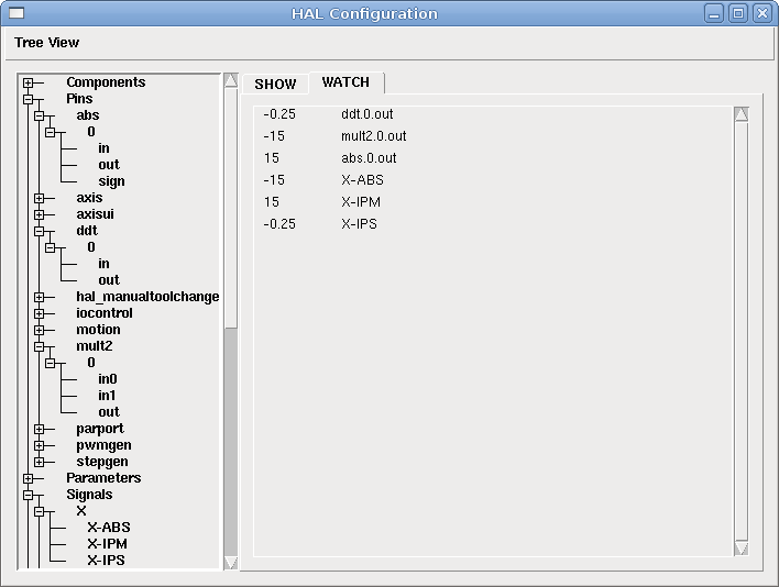
Dieses Beispiel verwendet ddt, mult2 und abs, um die Geschwindigkeit einer einzelnen Achse zu berechnen. Weitere Informationen zu den Echtzeitkomponenten finden Sie in den Man Pages oder in der HAL Components List (HAL-Komponenten).
Als Erstes sollten Sie Ihre Konfiguration überprüfen, um sicherzustellen, dass Sie keine der Echtzeitkomponenten bereits verwenden. Öffnen Sie dazu das HAL-Konfigurationsfenster und suchen Sie nach den Komponenten im Pin-Bereich. Wenn dies der Fall ist, suchen Sie die .hal-Datei, in die sie geladen werden, und erhöhen Sie die Anzahl und passen Sie die Instanz auf den richtigen Wert an. Fügen Sie Folgendes zu Ihrer custom.hal-Datei hinzu.
Laden der Echtzeitkomponenten.
loadrt ddt count=1
loadrt mult2 count=1
loadrt abs count=1
Fügen Sie die Funktionen in einen Thread ein, damit dieser aktualisiert wird.
addf ddt.0 servo-thread
addf mult2.0 servo-thread
addf abs.0 servo-thread
Herstellen der Verbindungen.
setp mult2.in1 60
net xpos-cmd ddt.0.in
net X-IPS mult2.0.in0 <= ddt.0.out
net X-ABS abs.0.in <= mult2.0.out
net X-IPM abs.0.out
In diesem letzten Abschnitt setzen wir mult2.0.in1 auf 60, um die Zoll pro Sekunde in Zoll pro Minute (engl. IPM für inch per minute) umzuwandeln, die wir von ddt.0.out erhalten.
Der xpos-cmd sendet die befohlene Position an den ddt.0.in. Der ddt berechnet die Ableitung der Änderung des Eingangs.
Der ddt2.0.out wird mit 60 multipliziert und ergibt die IPM (Zoll/min).
Der mult2.0.out wird an den abs gesendet, um den absoluten Wert zu erhalten.
Die folgende Abbildung zeigt das Ergebnis, wenn sich die X-Achse mit 15 IPM in die Minusrichtung bewegt. Beachten Sie, dass wir den absoluten Wert entweder vom abs.0.out-Pin oder dem X-IPM-Signal erhalten können.
4. Details zum Softstart
Dieses Beispiel zeigt, wie die HAL-Komponenten Tiefpass, limit2 oder limit3 verwendet werden können, um die Änderungsgeschwindigkeit eines Signals zu begrenzen.
In diesem Beispiel haben wir einen Servomotor, der eine Drehbankspindel antreibt. Wenn wir nur die befohlenen Spindeldrehzahlen für den Servomotor verwenden würden, würde er versuchen, so schnell wie möglich von der aktuellen Drehzahl auf die befohlene Drehzahl zu kommen. Dies könnte zu Problemen führen oder den Antrieb beschädigen. Um die Änderungsrate zu verlangsamen, können wir die spindle.N.speed-out durch einen Begrenzer vor dem PID senden, so dass sich der PID-Befehlswert langsamer auf neue Einstellungen ändert.
Die drei eingebauten Komponenten, die ein Signal begrenzen, sind:
-
limit2 begrenzt den Bereich und die erste Ableitung eines Signals.
-
limit3 begrenzt den Bereich, die erste und zweite Ableitung eines Signals.
-
Tiefpass verwendet einen exponentiell gewichteten gleitenden Durchschnitt, um ein Eingangssignal zu verfolgen.
Weitere Informationen über diese HAL-Komponenten finden Sie in den Man Pages.
Geben Sie das Folgende in eine Textdatei namens softstart.hal ein. Wenn Sie mit Linux nicht vertraut sind, legen Sie die Datei in Ihr Home-Verzeichnis.
loadrt threads period1=1000000 name1=thread
loadrt siggen
loadrt lowpass
loadrt limit2
loadrt limit3
net square siggen.0.square => lowpass.0.in limit2.0.in limit3.0.in
net lowpass <= lowpass.0.out
net limit2 <= limit2.0.out
net limit3 <= limit3.0.out
setp siggen.0.frequency .1
setp lowpass.0.gain .01
setp limit2.0.maxv 2
setp limit3.0.maxv 2
setp limit3.0.maxa 10
addf siggen.0.update thread
addf lowpass.0 thread
addf limit2.0 thread
addf limit3.0 thread
start
loadusr halscope
Öffnen Sie ein Terminalfenster und führen Sie die Datei mit dem folgenden Befehl aus.
halrun -I softstart.hal
Wenn das HAL Oszilloskop zum ersten Mal startet, klicken Sie auf OK, um den Standardfaden zu akzeptieren.
Als nächstes müssen Sie die Signale zu den Kanälen hinzufügen. Klicken Sie auf Kanal 1 und wählen Sie dann Quadrat auf der Registerkarte Signale. Wiederholen Sie dies für die Kanäle 2-4 und fügen Sie Tiefpass, Limit2 und Limit3 hinzu.
Um ein Triggersignal einzurichten, klicken Sie auf die Schaltfläche Source None und wählen Sie Square. Die Schaltfläche ändert sich in Quelle Kanal 1.
Als nächstes klicken Sie im Optionsfeld Run Mode auf Single. Dadurch wird ein Lauf gestartet, und nach dessen Beendigung sehen Sie die Spuren (engl. traces).
Um die Signale zu trennen, damit Sie sie besser sehen können, klicken Sie auf einen Kanal und verwenden Sie dann den Pos-Schieberegler im vertikalen Feld, um die Positionen festzulegen.
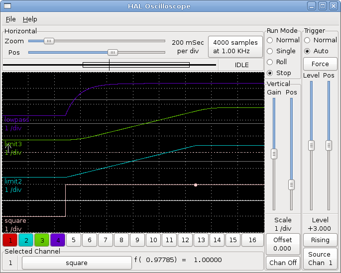
Um zu sehen, wie sich eine Änderung der Sollwerte der einzelnen Komponenten auswirkt, können Sie diese im Terminalfenster ändern. Um zu sehen, was verschiedene Verstärkungseinstellungen für den Tiefpass bewirken, geben Sie einfach Folgendes in das Terminalfenster ein und probieren Sie verschiedene Einstellungen aus.
setp lowpass.0.gain *.01Nachdem Sie eine Einstellung geändert haben, lassen Sie das Oszilloskop erneut laufen, um die Änderung zu sehen.
Wenn Sie fertig sind, geben Sie exit in das Terminalfenster ein, um halrun zu beenden und das halscope zu schließen. Schließen Sie das Terminal-Fenster nicht, während halrun läuft, da es einige Dinge im Speicher lassen könnte, die das Laden von LinuxCNC verhindern könnten.
Weitere Informationen zu Halscope finden Sie im HAL-Handbuch und im Tutorial.
5. Stand-Alone HAL
In manchen Fällen möchten Sie vielleicht einen GladeVCP-Bildschirm nur mit HAL betreiben. Nehmen wir an, Sie haben ein schrittmotorgesteuertes Gerät und alles was Sie benötigen ist diesen Schrittmotor zusteuern. Eine einfache Start/Stop Schnittstelle ist alles, was Sie für Ihre Anwendung benötigen, so dass Sie keine vollständige CNC-Anwendung laden und konfigurieren müssen.
Im folgenden Beispiel haben wir ein einfaches GladeVCP-Panel mit einem Schrittmotor.
# Lädt die GUI winder.glade und nennt diese winder
loadusr -Wn winder gladevcp -c winder -u handler.py winder.glade

# load Echtzeit-Komponenten
loadrt threads name1=fast period1=50000 fp1=0 name2=slow period2=1000000
loadrt stepgen step_type=0 ctrl_type=v
loadrt hal_parport cfg="0x378 out"

# fügt Funktionen den Threads hinzu
addf stepgen.make-pulses fast
addf stepgen.update-freq slow
addf stepgen.capture-position slow
addf parport.0.read fast
addf parport.0.write fast

# Erstellt Verbindungen in HAL
net winder-step parport.0.pin-02-out <= stepgen.0.step
net winder-dir parport.0.pin-03-out <= stepgen.0.dir
net run-stepgen stepgen.0.enable <= winder.start_button

# Start der Threads
start

# kommentieren Sie die folgenden Zeilen beim Testen aus und verwenden Sie die interaktive
# option halrun -I -f start.hal, um Pins etc. anzeigen zu können.

# Warten, bis die GladeVCP-GUI namens winder beendet ist
waitusr winder

# Stop HAL threads
stop

# "unload" aller Komponenten in HAL vor dem Beenden
unloadrt all