This document provides a reference to the basics of HAL.
1. HAL Commands
More detailed information can be found in the man page for halcmd: run man halcmd in a terminal window.
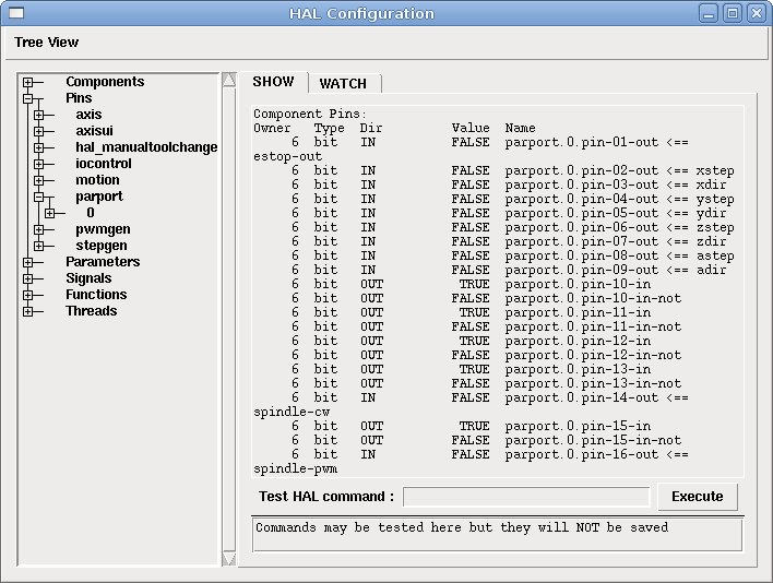
To see the HAL configuration and check the status of pins and parameters use the HAL Configuration window on the Machine menu in AXIS. To watch a pin status open the Watch tab and click on each pin you wish to watch and it will be added to the watch window.
1.1. loadrt
The command loadrt loads a real time HAL component.
Real time component functions need to be added to a thread to be updated at the rate of the thread.
You cannot load a non-realtime component into the realtime space.
loadrt <component> <options>
loadrt mux4 count=1
1.2. addf
The addf command adds a function to a real-time thread.
If the StepConf wizard was used to create the configuration, two threads have been created (``base-thread`` and ``servo-thread``).
addf adds function functname to thread threadname.
Default is to add the function in the order they are in the file.
If position is specified, adds the function to that spot in the thread.
A negative position indicates the position with respect to the end of the thread.
For example 1 is start of thread, -1 is the end of the thread, -3 is third from the end.
For some functions it is important to load them in a certain order, like the parport read and write functions.
The function name is usually the component name plus a number.
In the following example the component or2 is loaded and show function shows the name of the or2 function.
$ halrun
halcmd: loadrt or2
halcmd: show function
Exported Functions:
Owner   CodeAddr  Arg       FP   Users  Name
 00004  f8bc5000  f8f950c8  NO       0   or2.0
You have to add a function from a HAL real time component to a thread to get the function to update at the rate of the thread.
Usually there are two threads as shown in this example.
Some components use floating point math and must be added to a thread that supports floating point math.
The FP indicates if floating point math is supported in that thread.
$ halrun
halcmd: loadrt motmod base_period_nsec=55555 servo_period_nsec=1000000 num_joints=3
halcmd: show thread
Realtime Threads:
     Period  FP     Name               (     Time, Max-Time )
     995976  YES          servo-thread (        0,        0 )
55332 NO base-thread ( 0, 0 )-
base-thread (the high-speed thread): This thread handles items that need a fast response, like making step pulses, and reading and writing the parallel port. Does not support floating point math.
-
servo-thread (the slow-speed thread): This thread handles items that can tolerate a slower response, like the motion controller, ClassicLadder, and the motion command handler and supports floating point math.
addf <function> <thread>
addf mux4.0 servo-thread
|
Note
|
If the component requires a floating point thread that is usually the slower servo-thread. |
1.3. loadusr
The command loadusr loads a non-realtime HAL component.
Non-realtime programs are their own separate processes, which optionally talk to other HAL components via pins and parameters.
You cannot load realtime components into non-realtime space.
Flags may be one or more of the following:
|
-W
|
to wait for the component to become ready. The component is assumed to have the same name as the first argument of the command. |
|
-Wn <name>
|
to wait for the component, which will have the given <name>. This only applies if the component has a name option. |
|
-w
|
to wait for the program to exit |
|
-i
|
to ignore the program return value (with -w) |
|
-n
|
name a component when it is a valid option for that component. |
loadusrloadusr <component> <options> loadusr halui loadusr -Wn spindle gs2_vfd -n spindle
In English it means loadusr wait for name spindle component gs2_vfd name spindle.
1.4. net
The command net creates a connection between a signal and one or more pins.
If the signal does not exist net creates the new signal.
This replaces the need to use the command newsig.
The optional direction arrows <=, => and <=> make it easier to follow the logic when reading a net command line and are not used by the net command.
The direction arrows must be separated by a space from the pin names.
netnet signal-name pin-name <optional arrow> <optional second pin-name> net home-x joint.0.home-sw-in <= parport.0.pin-11-in
In the above example home-x is the signal name, joint.0.home-sw-in is a Direction IN pin, <= is the optional direction arrow, and parport.0.pin-11-in is a Direction OUT pin.
This may seem confusing but the in and out labels for a parallel port pin indicates the physical way the pin works not how it is handled in HAL.
A pin can be connected to a signal if it obeys the following rules:
-
An IN pin can always be connected to a signal.
-
An IO pin can be connected unless there’s an OUT pin on the signal.
-
An OUT pin can be connected only if there are no other OUT or IO pins on the signal.
The same signal-name can be used in multiple net commands to connect additional pins, as long as the rules above are obeyed.
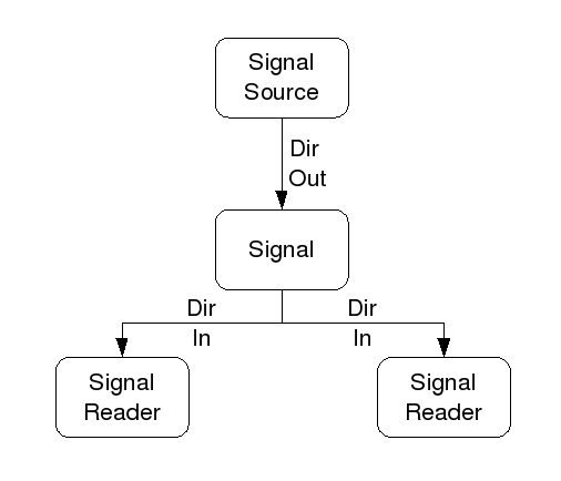
This example shows the signal xStep with the source being stepgen.0.out and with two readers, parport.0.pin-02-out and parport.0.pin-08-out.
Basically the value of stepgen.0.out is sent to the signal xStep and that value is then sent to parport.0.pin-02-out and parport.0.pin-08-out.
#   signal    source            destination          destination
net xStep stepgen.0.out => parport.0.pin-02-out parport.0.pin-08-out
Since the signal xStep contains the value of stepgen.0.out (the source) you can use the same signal again to send the value to another reader.
To do this just use the signal with the readers on another line.
#   signal       destination2
net xStep => parport.0.pin-06-out
An I/O pin like encoder.N.index-enable can be read or set as allowed by the component.
1.5. setp
The command setp sets the value of a pin or parameter.
The valid values will depend on the type of the pin or parameter.
It is an error if the data types do not match.
Some components have parameters that need to be set before use. Parameters can be set before use or while running as needed. You cannot use setp on a pin that is connected to a signal.
setpsetp <pin/parameter-name> <value> setp parport.0.pin-08-out TRUE
1.6. sets
The command sets sets the value of a signal.
setssets <signal-name> <value> net mysignal and2.0.in0 pyvcp.my-led sets mysignal 1
It is an error if:
-
The signal-name does not exist
-
If the signal already has a writer
-
If value is not the correct type for the signal
1.7. unlinkp
The command unlinkp unlinks a pin from the connected signal.
If no signal was connected to the pin prior running the command, nothing happens.
The unlinkp command is useful for trouble shooting.
unlinkpunlinkp <pin-name> unlinkp parport.0.pin-02-out
1.8. Obsolete Commands
The following commands are depreciated and may be removed from future versions.
Any new configuration should use the net command.
These commands are included so older configurations will still work.
1.8.1. linksp (deprecated)
The command linksp creates a connection between a signal and one pin.
linksplinksp <signal-name> <pin-name> linksp X-step parport.0.pin-02-out
The linksp command has been superseded by the net command.
1.8.2. linkps (deprecated)
The command linkps creates a connection between one pin and one signal.
It is the same as linksp but the arguments are reversed.
linkpslinkps <pin-name> <signal-name> linkps parport.0.pin-02-out X-Step
The linkps command has been superseded by the net command.
1.8.3. newsig
the command newsig creates a new HAL signal by the name <signame> and the data type of <type>.
Type must be bit, s32, u32 or float. Error if <signame> already exists.
newsignewsig <signame> <type> newsig Xstep bit
More information can be found in the HAL manual or the man pages for halrun.
2. HAL Data
2.1. Bit
A bit value is an on or off.
-
bit values = true or 1 and false or 0 (True, TRUE, true are all valid)
2.2. Float
A float is a floating point number. In other words the decimal point can move as needed.
-
float values = a 64 bit floating point value, with approximately 53 bits of resolution and over 210 (~ 1000) bits of dynamic range.
For more information on floating point numbers see:
2.3. s32
An s32 number is a whole number that can have a negative or positive value.
-
s32 values = integer numbers from -2147483648 to 2147483647
2.4. u32
A u32 number is a whole number that is positive only.
-
u32 values = integer numbers from 0 to 4294967295
3. HAL Files
If you used the Stepper Config Wizard to generate your config you will have up to three HAL files in your config directory.
-
my-mill.hal (if your config is named my-mill) This file is loaded first and should not be changed if you used the Stepper Config Wizard.
-
custom.hal This file is loaded next and before the GUI loads. This is where you put your custom HAL commands that you want loaded before the GUI is loaded.
-
custom_postgui.hal This file is loaded after the GUI loads. This is where you put your custom HAL commands that you want loaded after the GUI is loaded. Any HAL commands that use PyVCP widgets need to be placed here.
4. HAL Parameter
Two parameters are automatically added to each HAL component when it is created. These parameters allow you to scope the execution time of a component.
.time
|
Time is the number of CPU cycles it took to execute the function. |
.tmax
|
Tmax is the maximum number of CPU cycles it took to execute the function. |
tmax is a read/write parameter so the user can set it to 0 to get rid of the first time initialization on the function’s execution time.
5. Basic Logic Components
HAL contains several real time logic components. Logic components follow a Truth Table that states what the output is for any given input. Typically these are bit manipulators and follow electrical logic gate truth tables.
For further components see HAL Components List or the man pages.
5.1. and2
The and2 component is a two input and-gate.
The truth table below shows the output based on each combination of input.
and2 [count=N] | [names=name1[,name2...]]and2.nand2.N.in0 (bit, in)
and2.N.in1 (bit, in)
and2.N.out (bit, out)| in0 | in1 | out |
|---|---|---|
False |
False |
False |
True |
False |
False |
False |
True |
False |
True |
True |
True |
5.2. not
The not component is a bit inverter.
not [count=n] | [names=name1[,name2...]]not.all
not.nnot.n.in (bit, in)
not.n.out (bit, out)| in | out |
|---|---|
True |
False |
False |
True |
5.3. or2
The or2 component is a two input or-gate.
or2[count=n] | [names=name1[,name2...]]or2.nor2.n.in0 (bit, in)
or2.n.in1 (bit, in)
or2.n.out (bit, out)| in0 | in1 | out |
|---|---|---|
True |
False |
True |
True |
True |
True |
False |
True |
True |
False |
False |
False |
5.4. xor2
The xor2 component is a two input xor (exclusive or)-gate.
xor2[count=n] | [names=name1[,name2...]]xor2.nxor2.n.in0 (bit, in)
xor2.n.in1 (bit, in)
xor2.n.out (bit, out)| in0 | in1 | out |
|---|---|---|
True |
False |
True |
True |
True |
False |
False |
True |
True |
False |
False |
False |
6. Logic Examples
.Example using and2
loadrt and2 count=1
addf and2.0 servo-thread
net my-sigin1 and2.0.in0 <= parport.0.pin-11-in
net my-sigin2 and2.0.in1 <= parport.0.pin-12-in
net both-on parport.0.pin-14-out <= and2.0.out
In the above example one copy of and2 is loaded into real time space and added to the servo thread.
Next pin-11 of the parallel port is connected to the in0 bit of the and gate.
Next pin-12 is connected to the in1 bit of the and gate.
Last we connect the and2 out bit to the parallel port pin-14.
So following the truth table for and2 if pin 11 and pin 12 are on then the output pin 14 will be on.
7. Conversion Components
7.1. weighted_sum
The weighted sum converts a group of bits into an integer. The conversion is the sum of the weights of the bits present plus any offset. It’s similar to binary coded decimal but with more options. The hold bit interrupts the input processing, so that the sum value no longer changes.
weighted_sumloadrt weighted_sum wsum_sizes=size[,size,...]
Creates groups of ``weighted_sum``s, each with the given number of input bits (size).
To update the weighted_sum, the process_wsums must be attached to a thread.
process_wsums to servo threadaddf process_wsums servo-thread
Which updates the weighted_sum component.
In the following example, a copy of the AXIS HAL configuration window, bits 0 and 2 are TRUE, they have no offset. The weight (weight) of bit 0 is 1, that of bit 2 is 4, so the sum is 5.
| Owner | Type | Dir | Value | Name |
|---|---|---|---|---|
10 |
bit |
In |
TRUE |
|
10 |
s32 |
I/O |
1 |
|
10 |
bit |
In |
FALSE |
|
10 |
s32 |
I/O |
2 |
|
10 |
bit |
In |
TRUE |
|
10 |
s32 |
I/O |
4 |
|
10 |
bit |
In |
FALSE |
|
10 |
s32 |
I/O |
8 |
|
10 |
bit |
In |
FALSE |
|
10 |
s32 |
I/O |
0 |
|
10 |
s32 |
Out |
5 |
|