1. Introduction
MDRO is a simple graphical front-end for LinuxCNC providing a display of data from Digital Read Out (DRO) scales. It provides functionality similar to a normal machinist’s DRO display, allowing the user to use the DRO scales on the machine when operating in a manual-only (hand-cranked) mode. It is most useful for manual machines such as DRO equipped Bridgeport style mills that have been converted to CNC but still have the manual controls.
MDRO is mouse and touch screen friendly.
2. Getting Started
If your configuration is not currently set up to use MDRO,
you can change it by editing the INI file. In the
[DISPLAY] section, change the DISPLAY = line to read
DISPLAY = mdro. MDRO defaults to XYZ for the axes but that can
be changed.
Set [DISPLAY] section GEOMETRY = XYZ for a 3 axis mill. A lathe with
with DRO scales on the X and Z axes might use GEOMETRY = XZ.
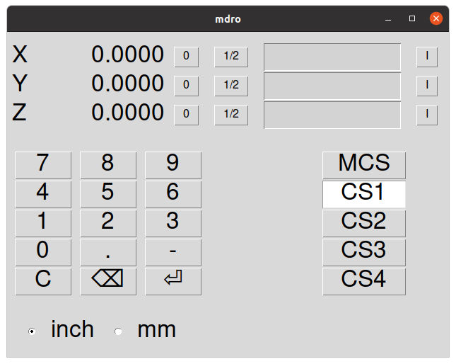
When MDRO starts, a window like the one in the figure [fig:mdro-window] above opens.
2.1. INI File Options
Other options that can be included on the [DISPLAY] section include:
-
MDRO_VAR_FILE = <file.var>- preload G54 - G57 coordinate system data.-
Preload a .var file. This is typically the .var file used by the operational code.
-
-
POINT_SIZE = <n>- Set text point size.-
This option sets the size of the font used which sets the overall size of the window. The default point size is 20, Typical sizes are 20 to 30.
-
-
MM = 1Set this if the DRO scales provide data scaled in millimeters.
2.2. Command Line Options
MDRO can be started by a loadusr command in a HAL file. Options equivalent
to those in the INI file can be set on the command line:
-
-l <file.var>- preload G54 - G57 coordinate system data. -
-p <n>- Set text point size. -
-m- Set this if the DRO scales provide data scaled in millimeters. -
<axes>- axes to display. SeeGEOMETRYabove.
2.3. Pins
Using an example of "XYZA" for an AXES argument, these pins will be created when MDRO starts:
mdro.axis.0
mdro.axis.1
mdro.axis.2
mdro.axis.3
mdro.index-enable.0
mdro.index-enable.1
mdro.index-enable.2
mdro.index-enable.3
In this example, the first row of the display will be labeled X and will
show the data from the DRO scale connected to pin mdro.axis.0. The
mdro.index-enable.n pins should be connected to the index pins of the DRO
if the DRO supports them.
The pins must be connected in the
file specified in the POSTGUI_HALFILE entry of the INI file when the
program is started from an INI file. They can be set directly after the
loadusr command if the program is started in a HAL file.
3. MDRO Window
The MDRO window contains the following elements:
-
A row for each axis. Each row includes:
-
the name of the axis,
-
the current value,
-
a "z" button that zeros the value,
-
a "1/2" button that halves the value,
-
a entry field that can be used to set a user-defined value. This field can be set from the keyboard or from the on-screen keypad.
-
A "I" button that starts an index operation (see below),
-
-
a keypad used to set values in the entry field via a mouse or touchscreen,
-
coordinate system selection buttons:
-
The "mcs" button selects the machine coordinate system. These are the raw values from the encoders connected to the
mdro.axis.npins. -
The "cs1" - "cs4" buttons allow the user to select among one of four user-defined coordinate systems. If the program is started with the
MDRO_VAR_FILE =option, the labels will be changed to "g54" - "g57" and the values from the specified .var file will be preloaded. Note that any changes to the values are not persistent: the .var file is never changed.
-
-
Inch/Millimeter selection buttons.
4. Index operations
MDRO supports DRO scales with index marks. Hit the "I" button on the
axis row then crank the axis to the index position. The machine
coordinate will be zeroed. This is easiest to see at startup or when the "mcs"
coordinate system has been selected.
5. Simulation
The easiest way to see how MDRO works is to try it in a simulation
environment. Add this section to the end of your simulation HAL file,
usually "hallib/core_sim.hal":
loadusr -W mdro -l sim.var XYZ
net x-pos-fb  => mdro.axis.0
net y-pos-fb  => mdro.axis.1
net z-pos-fb  => mdro.axis.2