1. License
PlasmaC and all of its related software are released under GPLv2.
2. Introduction
PlasmaC is a plasma cutting configuration that is loaded on top of LinuxCNC v2.8 or later. It includes a HAL component plus GUI configurations for both Axis and Gmoccapy. There is also an option to have the Axis GUI display in portrait mode, see Axis <machine_name>.ini file.
The desired LinuxCNC GUI (Axis or Gmoccapy) with PlasmaC component loaded should be chosen prior to starting the LinuxCNC installation process as switching between Axis and Gmoccapy requires a fresh configuration to be created.
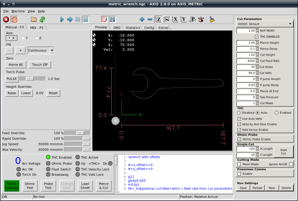
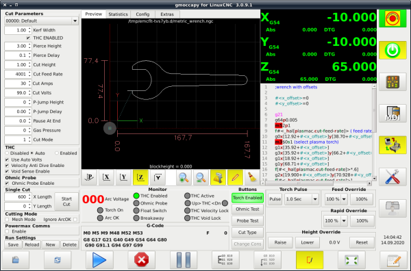
Screenshot examples of PlasmaC loaded on top of both the Axis and Gmoccapy GUIs are below:
AXIS:
GMOCCAPY:
The PlasmaC component should run on any hardware that is supported by LinuxCNC provided there are enough hardware I/O pins to fulfill the requirements of a plasma configuration.
If the user is new to CNC plasma cutting, it is recommended that they read the Plasma CNC Primer document which is a generic introduction to CNC plasma cutting.
|
Note
|
Except where noted, this guide assumes the user is using the latest version of PlasmaC. PlasmaC update notices are posted at: https://forum.linuxcnc.org/plasmac/37233-plasmac-updates Refer to PlasmaC Version to see the current PlasmaC version in the Config Panel. If the Version Number is not present, the user’s version of PlasmaC is before v0.121. See Update PlasmaC for information on updating PlasmaC. |
3. Installing LinuxCNC
The preferred method for installing LinuxCNC (which contains PlasmaC by default) is via an ISO image as described below.
|
Note
|
It is possible to install and run LinuxCNC on a variety of Linux distributions however that is beyond the scope of this User Guide. If the user wishes to install a Linux distribution other than those recommended, they will first need to install the preferred Linux distribution and then install LinuxCNC v2.8 or later along with any required dependencies. |
3.1. If The User Does Not Have Linux Installed
Installation instructions are available at: http://linuxcnc.org/docs/devel/html/getting-started/getting-linuxcnc.html
Following these instructions will yield a machine with the current stable branch (v2.8) of LinuxCNC.
3.2. If The User Has Linux with LinuxCNC v2.7
Upgrading instruction are available at: http://linuxcnc.org/docs/devel/html/getting-started/updating-linuxcnc.html
Following these instructions will yield a machine with the current stable branch (v2.8) of LinuxCNC.
3.3. Creating A Working Base Machine Configuration
|
Note
|
"Base machine configuration" means a complete working system without any of the plasma connections shown in the I/O Requirements section. All axes should be working and tuned for best performance and all home and limit switches for X, Y, and Z axes (if installed) should be operating correctly. |
|
Important
|
DO NOT ADD ANY OF THE PLASMA CONNECTIONS SHOWN IN THE I/O REQUIREMENTS SECTION AT THIS TIME, THESE I/O’S WILL BE ADDED LATER DURING THE PlasmaC CONFIGURATION USING THE CONFIGURATOR. |
Some recommended settings:
-
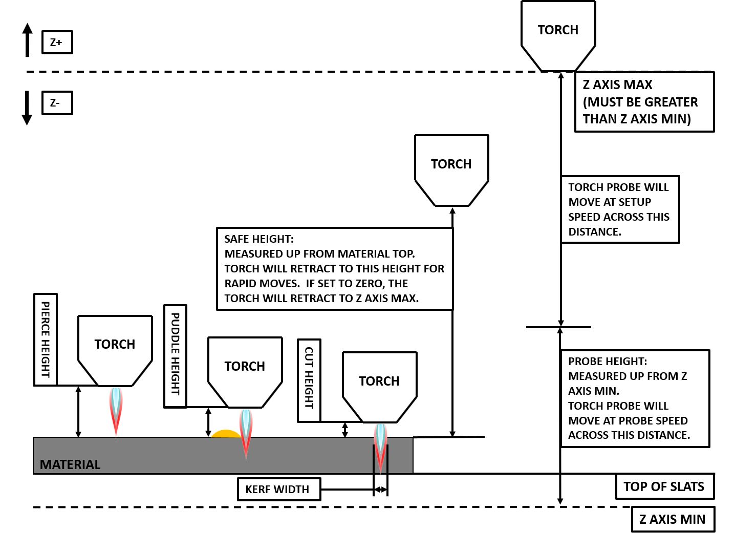
Z MINIMUM_LIMIT should be just below top of the slats with allowances for float_switch_travel and over travel tolerance. For example, if the user’s float switch takes 4mm (0.157") to activate then set the Z minimum to 5mm (0.197") plus an allowance for overrun (as calculated using the equation below) below the lowest slat.
-
Z MAXIMUM_LIMIT should be the highest the user wants the Z axis to travel (it must not be lower than Z HOME_OFFSET).
-
Z HOME should be set to be approximately 5mm (0.196") below the maximum limit.
-
Floating Head - it is recommended that a floating head be used and that it has enough movement to allow for overrun during probing. Overrun can be calculated using the following formula:
o = 0.5 × a × (v ÷ a)^2where: o = overrun, a = acceleration in units/sec2 and v = velocity in units/sec.
Metric example: given a Z axis MAX_ACCELERATION of 600mm/s2 and MAX_VELOCITY of 60mm/s, the overrun would be 3mm.
Imperial example: given a Z axis MAX_ACCELERATION of 24in/s2 and MAX_VELOCITY of 2.4in/s, the overrun would be 0.12in.
On machines that will utilize an ohmic probe as the primary method of probing, it is highly recommended to install a switch on the floating head as a backup means of stopping Z motion in the event of ohmic probe failure due to dirty surfaces.
The user may opt to create a base machine manually or one of the existing configuration helpers may be used:
|
Note
|
It is highly recommended to keep the base machine config simple until it has been fully tested and tuned. If using Stepconf or Pncconf then deselect the VCP Panel, spindle, manual tool change, and classic ladder options. Any of the aforementioned options can be added manually at a later time should the need arise. |
|
Important
|
DO NOT ADD ANY OF THE PLASMA SPECIFIC I/O REQUIREMENTS TO THE PNCCONF OR STEPCONF WIZARDS. |
If using a Mesa Electronics board, use the pncconf wizard (enter the following command into a terminal window):
pncconfIf using a parallel port, use the stepconf wizard (enter the following command into a terminal window):
stepconfIf using a Pico Systems board:
This LinuxCNC forum thread may be helpful.
If the user already has a dual motor gantry configuration that requires the configuration to be hand edited:
This LinuxCNC forum thread may be helpful.
|
Important
|
BEFORE PROCEEDING, THE USER SHOULD BE ABLE TO HOME THE MACHINE, ZERO EACH AXIS, JOG ALL AXES TO SOFT LIMITS WITHOUT CRASHING, AND RUN TEST G-CODE PROGRAMS WITHOUT ANY ERRORS. |
ONLY WHEN this criteria is met should the user proceed with configuring PlasmaC "on top" of a working machine by running the configurator.
|
Caution
|
DO NOT CONTINUE UNTIL THE BASE MACHINE IS CONFIGURED AND WORKING. |
4. Plasma Specific I/O Considerations
Prior to starting a plasma configuration, it is important that the user has a firm understanding of the operating modes available, as well as the I/O’s that are required for successful plasma operation.
4.1. Modes
PlasmaC requires the selection of one of following three operating modes:
Mode |
Description |
0 |
Uses an external arc voltage input to calculate both Arc Voltage (for Torch Height Control) and Arc OK. |
1 |
Uses an external arc voltage input to calculate Arc Voltage (for Torch Height Control). |
2 |
Uses an external Arc OK input for Arc OK. |
|
Important
|
If the plasma power source has an Arc OK (Transfer) output then it is recommended to use that for Arc OK rather than the soft (calculated) Arc OK provided by mode 0. |
4.2. Available I/Os
|
Note
|
This section only touches on the hardware I/O’s required for the PlasmaC component. Base machine requirements such as limit switches, home switches, etc. are in addition to these and should already be configured and working prior to the user running the configurator. |
Name |
Modes |
Description |
Arc Voltage |
0, 1 |
Analog input; optional. |
Arc OK |
1, 2 |
Digital input; optional. |
Float Switch |
0, 1, 2 |
Digital input; optional, see info below table: |
Ohmic Probe |
0, 1, 2 |
Digital input; optional, see info below table: |
Ohmic Probe Enable |
0, 1, 2 |
Digital output; optional, see info below table: |
Breakaway Switch |
0, 1, 2 |
Digital input; optional, see info below table: |
Torch On |
0, 1, 2 |
Digital output; required. |
Move Up |
2 |
Digital input; optional. |
Move Down |
2 |
Digital input; optional. |
Scribe Arming |
0, 1, 2 |
Digital output; optional. |
Scribe On |
0, 1, 2 |
Digital output; optional. |
Only one of either Float Switch or Ohmic Probe is required. If both are used then Float Switch will be a fallback if Ohmic Probe is not sensed.
If Ohmic Probe is used then Ohmic Probe Enable is required to be checked on the PlasmaC GUI.
Breakaway Switch is not mandatory because Float Switch is treated the same as a breakaway when not probing. If they are two separate switches, and there are not enough inputs on the breakout board, they could be combined and connected as a Float Switch.
|
Note
|
The minimum I/O requirement for a PlasmaC configuration to function are: Arc Voltage input OR Arc OK input, Float Switch input, and Torch On output. To reiterate, in this case PlasmaC will treat the float switch as a breakaway switch when it is not probing. |
|
Important
|
THE ABOVE PINS WILL BE ENTERED LATER DURING THE PLASMAC CONFIGURATOR PROCESS. MAKE NOTE OF THE CORRESPONDING INPUTS AND OUTPUTS ON THE BREAKOUT BOARD DURING WIRING. THESE PINS SHOULD NOT BE USED TO CREATE THE BASE MACHINE .HAL FILE. |
5. Installing PlasmaC To A Base Machine Via The Configurator
By this point, the user NEEDS to have a fully tested and working base machine configuration without any connections to the plasma specific I/Os before proceeding. It is much more difficult to edit a base machine configuration after adding PlasmaC as pncconf and stepconf can no longer be used to help edit the configuration.
|
Caution
|
DO NOT PROCEED UNTIL THE BASE MACHINE IS COMPLETE. |
|
Note
|
If the user is using a Mesa Electronics THCAD card for arc voltage measurement, see Mesa THCAD before proceeding. |
Installing a PlasmaC configuration to a base machine is done from the Configurator.
Enter the following command into a terminal window:
python /usr/share/doc/linuxcnc/examples/sample-configs/by_machine/plasmac/configurator.py5.1. Configure
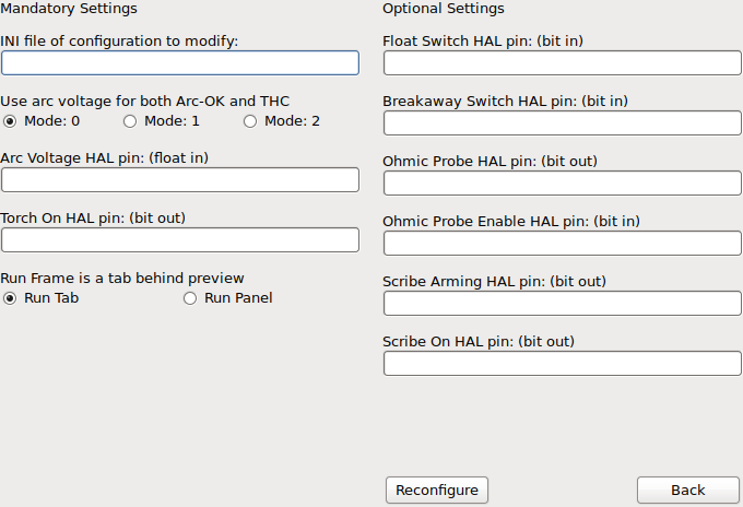
The selection window is now visible:

Select New from the selection window, this will show an info dialog, select Continue and the New Configuration window will display.
|
Note
|
There will be different fields visible depending on the mode selected. |
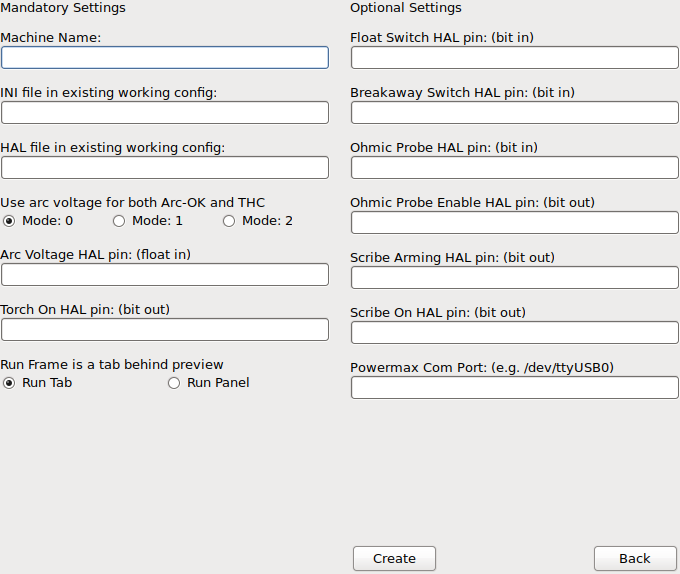
HAL connection examples in the following table show examples for both a parallel port config and a Mesa 7i96 config. Change the pin names as required to suit the breakout board configuration.
Field |
Description |
Examples |
Machine Name |
The new name for the machine. This will create a ~/linuxcnc/<machine_name> directory and a <machine_name>.ini file. |
plasma_table.ini. |
INI File |
This is the .ini file that was created as a result of making a working and tested base machine configuration. |
base.ini |
HAL File |
This is the .hal file that was created as a result of making a working and tested base machine configuration. |
base.hal |
Mode |
Select the required mode based on the following criteria: |
1 |
Arc Voltage |
Required for Modes 0 and 1 only. |
Parallel Port Example: encoder.0.velocity |
Torch On |
Required for All modes. |
Parallel Port Example: parport.0.pin-16-out |
Arc OK |
Required for Modes 1 and 2 only. |
Parallel Port Example: parport.0.pin-10-in-not |
Ohmic Probe |
Required if using an ohmic probe. |
Parallel Port Example: parport.0.pin-11-in |
Ohmic Probe Enable |
Required if using an ohmic probe. |
Parallel Port Example: parport.1.pin-01-out |
Float Switch |
Required if using a float switch. |
Parallel Port Example: parport.0.pin-12-in |
Breakaway Switch |
Required if using a breakaway switch. |
Parallel Port Example: parport.0.pin-13-in |
Move Up |
Required for Mode 2 only. |
Parallel Port Example: parport.1.pin-10-in |
Move Down |
Required for Mode 2 only. |
Parallel Port Example: parport.1.pin-11-in |
Run Panel |
Run Tab - Selecting this option places the PlasmaC run frame in a tab behind the preview tab. |
Run Tab |
Scribe Arming |
Required if using a scribe. |
Parallel Port Example: parport.1.pin-16-out |
Scribe On |
Required if using a scribe. |
Parallel Port Example: parport.1.pin-16-out |
PowerMax Comms |
Required if using PowerMax serial communications. |
/dev/ttyUSB0 |
|
Note
|
If unsure of the HAL pin’s full name, the user may start LinuxCNC for the base machine and run HalShow for a full listing of all HAL pins. |
Fill in the required entries to suit the machine wiring/breakout board configuration, click Create and a working PlasmaC configuration will be created in the following directory: ~/linuxcnc/configs/<machine_name>
The newly created PlasmaC configuration can be run by entering the following command into a terminal window (change "<machine_name>" to the machine name entered into the PlasmaC configurator):
linuxcnc ~/linuxcnc/configs/<machine_name>/<machine_name>.iniAfter creating a new configuration some initial setup is required before using the PlasmaC component.
5.2. Initial Setup
The following heights diagram will help the user visualize the different heights involved in plasma cutting and how they are measured:
After running the command at the end of section 5.1, LinuxCNC should be running with the PlasmaC panels visible.
Click on the Config tab to open the Config Panel and ensure every one of these settings is tailored to the machine.
To set the Z axis DRO relative to the Z axis MINIMUM_LIMIT, the user should perform the following steps. It is important to understand that in PlasmaC, touching off the Z axis DRO has no effect on the Z axis position while running a G-Code program. These steps simply allow the user to more easily set the probe height as after performing the steps, the displayed Z axis DRO value will be relative to Z axis MINIMUM_LIMIT.
-
The user should be familiar with the recommended Z Axis Settings
-
Home the Z axis.
-
Ensure there is nothing below the torch then jog the Z axis down until it stops at the Z axis MINIMUM_LIMIT then click Touch Off with the Z axis selected to set the Z axis at zero offset.
-
Home the Z axis again.
If the machine is equipped with a float switch then the user will need to set the offset in the Config Panel. This will be done by running a "Probe Test" cycle.
-
Check that the Probe Speed and the Probe Height in the Config Panel are correct. PlasmaC can probe at the full Z axis velocity so long as the machine has enough movement in the float switch to absorb any overrun. If the machine is suitable, the user could set the Probe Height to a value near the Z axis minimum and do all probing at full speed.
-
If the machine is not already homed and in the home position, Home the machine.
-
Place some material on the slats under the torch.
-
Press the Probe Test button.
-
The Z axis will probe down, find the material then move up to the specified Pierce Height as set by the currently selected material. The torch will wait in this position for the time set in the <machine_name>.ini file. The default probe test hold time is 30 seconds, this value may be edited in the <machine_name>.ini file. After this the torch will return to the starting height.
-
Measure the distance between the material and the tip of the torch while the torch is waiting at Pierce Height.
-
If the measurement is greater than the Pierce Height of the currently selected material, then reduce the "Float Travel" on the Config Panel by the difference between the measured value and the specified value. If the measurement is less than Pierce Height of the currently selected material, then increase the "Float Travel" on the Config Panel by the difference between the specified value and the measured value.
-
After the adjustments to the "Float Travel" have been made, repeat the process from #4 above until the measured distance between the material and the torch tip matches the Pierce Height of the currently selected material.
|
Note
|
If the amount of time between the torch contacting the material and when the torch moves up and comes to rest at the Pierce Height seems excessive, see the probing section for a possible solution. |
|
Important
|
IF USING A Mesa Electronics THCAD THEN UP UNTIL NOW THE Voltage Scale VALUE WAS OBTAINED MATHEMATICALLY. IF THE USER INTENDS TO USE CUT VOLTAGES FROM A MANUFACTURE’S CUT CHART THEN IT WOULD BE ADVISABLE TO DO MEASUREMENTS OF ACTUAL VOLTAGES AND FINE TUNE THE Voltage Scale AND Voltage Offset. |
|
Caution
|
PLASMA CUTTING VOLTAGES CAN BE LETHAL, IF THE USER IS NOT EXPERIENCED IN DOING THESE MEASUREMENTS GET SOME QUALIFIED HELP. |
5.3. Reconfigure An Existing PlasmaC Configuration
The Configurator may also be used to reconfigure an existing PlasmaC configuration to change settings instead of modifying files manually.
The Configurator is only able to modify:
-
The HAL pins connecting PlasmaC to the machine.
-
The mode used by PlasmaC.
-
The position of the Run Panel in the GUI.
Reconfiguring a PlasmaC configuration is done from the Configurator which is located in the configuration directory.
It is recommended that a backup copy of the existing PlasmaC configuration is made before proceeding.
To start the configurator enter the following command into a terminal window:
python linuxcnc/<the_users_configuration_directory>/configurator.pyThe selection window is now visible:

Select Reconfigure from the selection window, this shows an info dialog, select Continue and the Reconfigure window will display:
Select the <machine_name>.ini file of the PlasmaC configuration to reconfigure.
If the user changes modes, the entry boxes will change depending on the currently selected mode.
When all entries are correct, click Reconfigure and the user’s PlasmaC configuration will be reconfigured.
Entry descriptions can be found here
|
Note
|
Machine Name and <machine_name>.hal File can not be modified. |
6. Other PlasmaC Setup Considerations
6.1. Lowpass Filter
The PlasmaC component has an built in lowpass filter that if used is applied to the plasmac.arc-voltage-in input pin to filter any noise that could cause erroneous voltage readings. The lowpass filter should only be used after using Halscope to determine the required frequency and whether the amplitude of the noise is large enough to cause any issues. For most plasma machines lowpass is not required and should not be used unless it is required.
The HAL pin assigned to this filter is plasmac.lowpass-frequency and is set to 0 (disabled) by default. To apply a lowpass filter to the arc-voltage, the user would edit the following entry in the <machine_name>_connections.hal file in the machine’s configuration directory to add the appropriate cutoff frequency as measured in Hertz (Hz).
For example:
setp plasmac.lowpass-frequency 100The above example would give a cutoff frequency of 100Hz.
6.2. Contact Debounce
Contact bounce from mechanical relays, switches, or external interference may cause some inconsistent behavior of the following switches:
-
Float Switch
-
Ohmic Probe
-
Breakaway Switch
-
Arc OK (for modes 1 & 2)
Due to the fact that the software is capable of sampling rates faster than the contact bounce period, it is possible that the software may see contact bounce as several changes in input states occurring in a very small time period, and incorrectly interpreting a very quick on-off of the input. One method of mitigating contact bounce is to "debounce" the input. To summarize debounce, as soon as the software sees an input with a debounce delay change states, it waits for a prescribed delay period before checking the state of the input again. After the debounce period the software will regard state changes as normal behavior of the input and react accordingly.
Debounce periods can be changed by editing the appropriate debounce value in the <machine_name>_connections.hal file in the <machine_name> config folder.
Each increment of delay adds one servo thread cycle to the debounce time. For example: given a servo thread period of 1000000 (measured in nano seconds), a debounce delay of 5 would equate to 5000000ns, or 5ms.
For the Float and Ohmic switches this equates to a 0.001mm (0.00004") increase in the probed height result.
It is recommended to keep the debounce values as low as possible while still achieving consistent results. Using Halscope to plot the inputs is a good way to establish the correct value.
There are two versions of contact debouncing available in PlasmaC. The method used is determined by when the configuration was first created. There is no automatic update method available to convert from the original debounce setup to the alternate debounce setup as it is difficult to apply the necessary changes without understanding any manual edits that may have been made to the machine’s configuration files and potentially "breaking" a working configuration. If the user wishes to change from the original setup to the new setup, they must do so manually.
6.2.1. Debounce (For PlasmaC installations using v0.173 and later)
For PlasmaC installations using v0.173 (released 11 Sep 2020) and later, debounce is achieved by using the HAL dbounce component which is a later alternative to the original debounce component. This new version allows for the loading and naming of individual debounce instances and is compatible with Twopass HAL file processing.
All four signals above have an individual debounce component so the debounce periods can be catered individually to each input. Any changes made to these values in the <machine_name>_connections.hal file will not be overwritten by later updates of PlasmaC.
The default delay for all four inputs is five servo thread periods. In most cases this value will work quite well. If any of the inputs do not use mechanical switches, it may be possible to either reduce or remove the delay for those inputs.
If debounce is required for other equipment like home or limit switches etc then more dbounce components may added in any of the HAL files without any regard to the signals listed here.
6.2.2. Debounce (For PlasmaC installations using v0.172 and earlier)
For PlasmaC installations using v0.172 (released 10 Sep 2020) and earlier, debounce is achieved by using the HAL debounce component. If the user installed PlasmaC using a version before v0.173 (released 11 Sep 2020), and they wish to use the new debounce method, they will need to follow the directions in the Changing Debounce Type section.
In a standard configuration created before this date, only the Float Switch, Ohmic Probe, and Breakaway Switch inputs are debounced and the single delay value applies to all three switches simultaneously. These inputs could separated and controlled individually by using an exclusive debounce group for each signal.
If debounce is required for other equipment like home or limit switches then either more filters could be added to the existing group or another group could be added by editing the existing loadrt debounce line in the <machine_name>_connections.hal file.
Change the default line below:
loadrt debounce cfg=3to:
loadrt debounce cfg=4This would add a new filter named debounce.0.3 that could be used to debounce another switch input signal.
Change the default line below (and add the two additional lines):
loadrt debounce cfg=3to:
loadrt debounce cfg=3,1
setp   debounce.1.delay n
addf   debounce.1 servo-thread
This would add a new group named debounce.1 with a new filter named debounce.1.0 having a delay of n servo cycles that could be used to debounce another switch input signal. The user will have to change "n" to the appropriate amount of delay for the new input.
6.2.3. Changing Debounce Type
It is possible to manually change from the old debounce setup to the later debounce setup by editing the <machine_name>_connections.hal file. If this is done, the naming convention as used in this example connections.hal file must be followed.
It is also necessary to edit the <machine_name>.ini file to add the following change:
# required for upgrades (DO NOT CHANGE)
LAST_MAJOR_UPGRADE      = 0.144
to:
# required for upgrades (DO NOT CHANGE)
LAST_MAJOR_UPGRADE      = 0.144
DBOUNCE                 = 1
Failure to follow this procedure will lead to errors when loading LinuxCNC.
6.3. Desktop Launcher
If a link to the launch the configuration was not created when creating the config, the user could create a desktop launcher to the config by right clicking on the desktop and selecting Create Launcher or similar. This will bring up a dialog to create a launcher. Give the icon a nice short name, enter anything for the command and click OK.
After the launcher appears on the desktop, right click on it and then edit it with the user’s editor of choice. Edit the file so it looks similar to:
[Desktop Entry]
Comment=
Terminal=false
Name=LinuxCNC
Exec=sh -c "linuxcnc $HOME/linuxcnc/configs/<machine_name>/<machine_name>.ini"
Type=Application
Icon=/usr/share/pixmaps/linuxcncicon.png
If the user would like a terminal window to open behind the GUI window then change the Terminal line to:
Terminal=trueDisplaying a terminal can be handy for error and information messages.
6.4. PlasmaC Files
After a successful PlasmaC installation, the following files are created in the configuration directory:
Filename |
Function |
<machine_name>.ini |
A configuration file that includes the base system parameters, as well as various settings required by PlasmaC. |
<machine_name>.hal |
A HAL connections file that includes the base system I/O HAL pin connections to LinuxCNC. |
<machine_name>_connections.hal |
A HAL connections that includes I/O HAL pin connections specific to PlasmaC. |
<machine_name>_material.cfg |
This file is used to store the material settings from the Run Panel |
postgui.tcl |
A HAL file that is ran after the GUI has loaded for user customizing. |
tool.tbl |
A tool table used to store offset information for additional tools (scribe, etc.) used by the PlasmaC configuration. |
|
Note
|
<machine_name> is whatever name the user entered into the "Machine Name" field of the configurator NOTE: Custom commands are allowed in <machine_name>_connections.hal and the postgui.hal files as they are not overwritten during updates. |
In addition to the above files, the following links are created to files or directories in the source directory:
Filename |
Function |
test |
A directory containing a test panel for simulation configurations. |
wizards |
A directory containing the files relating to the shape library to support the Conversational feature within PlasmaC. |
configurator.py |
A Python script used to configure a new PlasmaC configuration. It is also used to updates/re-configure an existing PlasmaC configuration. |
materialverter.py |
A Python script used to convert tool libraries from various CAM software and populate the PlasmaC material file. |
pmx_test.py |
A Python script used to provide a panel to find the correct serial port and test communications between PlasmaC and a PowerMax power source. |
versions.html |
A HTML file that will list the complete version and update history of PlasmaC. |
Finally, the following directories are created:
Folder |
Function |
backup |
A directory that contains backups of files that changed during updates to an existing installation and the original .hal and .ini files. |
plasmac |
A directory that contains links to the PlasmaC source files. |
After running a new configuration for the first time the following files will be created in the configuration directory:
Filename |
Function |
<machine_name>_config.cfg |
This file is used to store the configuration settings from the Config Panel |
<machine_name>_run.cfg |
This file is used to store the configuration settings from the Run Panel |
<machine_name>_wizards.cfg |
This file is used to store the configuration settings from the Conversational shape library |
plasmac_stats.var |
This file is used to store the saved cutting statistics |
|
Note
|
The configuration files (<machine_name>.ini and <machine_name>.hal) that are created by PlasmaC are notated to explain the requirements to aid in manual manipulation of these configurations. They may be edited with any text editor. |
|
Note
|
The .cfg files are plain text and may be edited with any text editor. |
6.5. INI File
PlasmaC requires some specific <machine_name>.ini file variables as follows:
6.5.1. Common
[PLASMAC] Section
MODE                = 0 (use external arc voltage in for Arc Voltage)
                        (use external arc voltage in for Arc OK)
                    = 1 (use external arc voltage in for Arc Voltage)
                        (use external Arc OK in for Arc OK)
                    = 2 (Use external Arc OK in for Arc OK)
                        (use external up/down for THC)

CONFIG_DISABLE      = 0 (0=enable or 1=disable the PlasmaC Config Panel)
PAUSED-MOTION-SPEED = n (multiply cut-feed-rate by this value for paused motion speed)
TORCH-PULSE-TIME    = n (torch on time when manual pulse requested)
BUTTON_n_NAME       = <NAME> (the name of a custom user buttons)
BUTTON_n_CODE       = <CODE> (the code run by a custom user button)
BUTTON_n_IMAGE      = <IMAGE> (the image displayed by buttons 10~19)
[FILTER] Section
PROGRAM_EXTENSION       = .ngc (filter gcode files)
ngc                     = ./plasmac/plasmac_gcode.py
nc                      = ./plasmac/plasmac_gcode.py
tap                     = ./plasmac/plasmac_gcode.py
[RS274NGC] Section
RS274NGC_STARTUP_CODE = o<metric_startup> call (machine startup G-Code)
SUBROUTINE_PATH       = ./:./plasmac:../../nc_files/subroutines (./ must be in this path)
FEATURES              = 12 (for reading .ini and HAL variables)
USER_M_PATH = ./:./plasmac (for M190 material change)|
Important
|
SEE PATH TOLERANCE FOR RS274NGC_STARTUP_CODE INFORMATION RELATED TO G64. |
[HAL] Section
TWOPASS = on (needed for multiple .hal files)
HALFILE = <machine_name>.hal (your base machine .hal file)
HALFILE = plasmac.tcl (the standard PlasmaC .hal file )
HALFILE = <machine_name>_connections.hal (PlasmaC connections to the machine)
HALFILE = HALUI   = halui (required)
The <machine_name>.hal file has num_spindles=[TRAJ]SPINDLES appended to the end of the loadrt motmod line to allow the addition of a scribe, if required.
|
Note
|
The user could place custom HAL commands in the <machine_name>_connections.hal file as this file is not overwritten by PlasmaC updates. |
[TRAJ] Section
SPINDLES = 3[AXIS_X] Section
MAX_VELOCITY     = double the value in the corresponding joint
MAX_ACCELERATION = double the value in the corresponding joint
OFFSET_AV_RATIO  = 0.5
[AXIS_Y] Section
MAX_VELOCITY     = double the value in the corresponding joint
MAX_ACCELERATION = double the value in the corresponding joint
OFFSET_AV_RATIO  = 0.5
[AXIS_Z] Section
MIN_LIMIT        = the top of your slats or just below
MAX_VELOCITY     = double the value in the corresponding joint
MAX_ACCELERATION = double the value in the corresponding joint
OFFSET_AV_RATIO = 0.5|
Note
|
PlasmaC uses the LinuxCNC External Offsets feature for all Z axis motion, and for moving the X and/or Y axis for a consumable change while paused. For more information on this feature, please read External Axis Offsets in the LinuxCNC documentation. |
6.5.2. Axis GUI Specific
[PLASMAC] Section
FONT        = sans 10 (valid font sizes are from 9 to 15 inclusive)
THEME       = Clearlooks (any installed theme, only for the plasmaC tabs)
WINDOW_SIZE = 0 (0 = minimum size to suit font, 1 = maximised, width x height = custom size)
AXIS_ORIENT = portrait
Defaults for the above parameters if they are not specified are:
FONT        = sans 10
THEME       = current system theme
WINDOW_SIZE = minimum size to suit font
AXIS_ORIENT = landscape
Changing the FONT size changes the minimum window size. PlasmaC requires a larger window size than the standard Axis window. Window size varies depending on whether the user has chosen to view the Run Panel as a Tab or a Panel on the right side of the GUI. If using portrait mode then window height will vary depending on whether or not the user has a rotary axis. If the window doesn’t completely fit on the screen then the user will need to reduce the font size.
Custom window size is specified as width x height e.g. 1600 x 900. Spaces are ignored but may be used for readability and x may be lower or upper case.
|
Note
|
WINDOW_SIZE has replaced MAXIMISED. For backwards compatibility these names are interchangeable. |
[DISPLAY] Section
TOOL_EDITOR       = tooledit x y
USER_COMMAND_FILE = plasmac_axis.py.py

EMBED_TAB_NAME    = Statistics
EMBED_TAB_COMMAND = gladevcp -c plasmac_stats -x <XID> -u ./plasmac/plasmac_stats.py -H ./plasmac/plasmac_stats.hal ./plasmac/plasmac_stats.glade

#use one of the next two

#run frame in tab behind preview
EMBED_TAB_NAME    = Plasma Run
EMBED_TAB_COMMAND = gladevcp -c plasmac_run -x <XID> -u ./plasmac/plasmac_run.py -H ./plasmac/plasmac_run.hal ./plasmac/plasmac_run_tab.glade

#run frame in panel on right side
#GLADEVCP = -c plasmac_run -u ./plasmac/plasmac_run.py -H ./plasmac/plasmac_run.hal ./plasmac/plasmac_run_panel.glade

EMBED_TAB_NAME    = Plasma Config
EMBED_TAB_COMMAND = gladevcp -c plasmac_config -x <XID> -u ./plasmac/plasmac_config.py -H ./plasmac/plasmac_config.hal ./plasmac/plasmac_config.glade

EMBED_TAB_NAME    = Extras
EMBED_TAB_COMMAND = gladevcp -c plasmac_wizards -x {XID} -u ./plasmac/plasmac_wizards.py ./plasmac/plasmac_wizards.glade
The Run Window can be displayed as either:
-
A panel on the right side of the Axis GUI which is suitable for widescreen displays.
-
A tab behind the Preview tab which is suitable for 4:3 ratio displays.
6.5.3. Gmoccapy GUI Specific
[DISPLAY] section
EMBED_TAB_NAME     = plasmac_buttons
EMBED_TAB_LOCATION = box_cooling
EMBED_TAB_COMMAND  = gladevcp -c plasmac_buttons -x <XID> -u ./plasmac/plasmac_buttons.py -H ./plasmac/plasmac_buttons.hal ./plasmac/plasmac_buttons.glade
EMBED_TAB_NAME     = plasmac_control
EMBED_TAB_LOCATION = box_spindle
EMBED_TAB_COMMAND  = gladevcp -c plasmac_control -x <XID> -u ./plasmac/plasmac_control.py -H ./plasmac/plasmac_control.hal ./plasmac/plasmac_control.glade
EMBED_TAB_NAME     = Statistics
EMBED_TAB_LOCATION = ntb_preview
EMBED_TAB_COMMAND  = gladevcp -c plasmac_stats -x <XID> -u ./plasmac/plasmac_stats.py -H ./plasmac/plasmac_stats.hal ./plasmac/plasmac_stats.glade
EMBED_TAB_NAME     = Plasma Run

#use one of the next two

#run panel in tab behind preview
EMBED_TAB_LOCATION  = ntb_preview
EMBED_TAB_COMMAND   = gladevcp -c plasmac_run -x <XID> -u ./plasmac/plasmac_run.py -H ./plasmac/plasmac_run.hal ./plasmac/plasmac_run_tab.glade

#run panel in panel on left side
#EMBED_TAB_LOCATION = box_left
#EMBED_TAB_COMMAND  = gladevcp -c plasmac_run -x <XID> -u ./plasmac/plasmac_run.py -H ./plasmac/plasmac_run.hal ./plasmac/plasmac_run_panel.glade

EMBED_TAB_NAME     = Plasma Config
EMBED_TAB_LOCATION = ntb_preview
EMBED_TAB_COMMAND  = gladevcp -c plasmac_config -x <XID> -u ./plasmac/plasmac_config.py -H ./plasmac/plasmac_config.hal ./plasmac/plasmac_config.glade
EMBED_TAB_NAME     = plasmac_monitor
EMBED_TAB_LOCATION = box_tool_and_code_info
EMBED_TAB_COMMAND  = gladevcp -c plasmac_monitor -x <XID> -u ./plasmac/plasmac_monitor.py -H ./plasmac/plasmac_monitor.hal ./plasmac/plasmac_monitor.glade

EMBED_TAB_NAME     = Extras
EMBED_TAB_LOCATION = ntb_preview
EMBED_TAB_COMMAND  = gladevcp -c plasmac_wizards -x {XID} -u ./plasmac/plasmac_wizards.py ./plasmac/plasmac_wizards.glade
The Run Window can be displayed as either:
-
A panel on the left side of the Gmoccapy GUI which is suitable for widescreen displays.
-
A tab behind the Preview tab which is suitable for 4:3 ratio displays.
7. Using PlasmaC
Once PlasmaC is successfully installed, no Z axis motion is required to be part of the G-Code cut program. In fact, if any Z axis references are present in the cut program, the standard PlasmaC configuration will remove them during the program loading process.
For reliable use of PlasmaC the user should NOT use any Z axis offsets other than the coordinate system offsets (G54-G59.3).
Due to the way PlasmaC handles Z movements automatically, it is best to park the Z axis approximately 5mm (0.2") below the Z axis maximum limit (torch farthest away from the work piece) prior to performing any manual cuts or running any G-Code programs.
7.1. PlasmaC GUI Panels
PlasmaC makes several modifications to the GUI. Some additions are panels on permanent display and others are tabs behind the preview tab.
Some functions/features are only used for particular modes and are not displayed if they are not required by the chosen PlasmaC mode.
7.1.1. Config Panel
This panel is used to display configuration parameters that are modified infrequently.
It is possible to disable this panel so machine settings cannot be modified by unauthorized personnel. This is achieved by setting the following variable in the <machine_name>.ini file:
[PLASMAC] CONFIG_DISABLE = 1If it is necessary for authorized personnel to modify the configuration after disabling the Config Panel, A HAL pin named plasmac_config.config-disable can be set to 0 (zero) to enable the panel. This pin could be tied to a physical key-switch or similar on the cabinet so that only authorized personnel could enable the Config Panel to change settings.
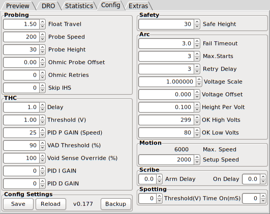
Probing
Name |
Description |
Float Travel |
This sets the amount of travel the float switch moves before completing the float switch circuit. This distance can be measured by using the Probe Test button, and the method described in Initial Setup. |
Probe Speed |
This sets the speed at which the torch will probe to find the material after it moves to the Probe Height. |
Probe Height |
This sets the height above the Z axis minimum limit that Probe Speed begins. |
Ohmic Probe Offset |
This sets the distance above the material the torch will should go after a successful ohmic probe. It is mainly used to compensate for high probing speeds. |
Ohmic Retries |
This sets the number of times PlasmaC will retry a failed ohmic probe before falling back to the float switch for material detection. |
Skip IHS |
This sets the distance threshold used to determine if an Initial Height Sense (probe) can be skipped for the current cut, see IHS Skip. |
|
Note
|
If the amount of time between the torch contacting the material and when the torch moves up and comes to rest at the Pierce Height seems excessive, see the probing section for a possible solution. |
THC
Name |
Modes |
Description |
Delay |
0, 1, 2 |
This sets the delay (in seconds) measured from the time the Arc OK signal is received until Torch Height Controller (THC) activates. |
Threshold (V) |
0, 1, 2 |
This sets the voltage variation allowed from the target voltage before for THC makes movements to correct the torch height. |
PID P Gain (Speed) |
0, 1 |
This sets the Proportional gain for the THC PID loop. This roughly equates to how quickly the THC attempts to correct changes in height. |
VAD Threshold (%) |
0, 1 |
(Velocity Anti Dive) This sets the percentage of the current cut feed rate the machine can slow to before locking the THC to prevent torch dive. |
Void Sense Override (%) |
0, 1 |
This sets the size of the change in cut voltage necessary to lock the THC to prevent torch dive (higher values need greater voltage change to lock THC). |
PID I Gain |
0, 1 |
This sets the Integral gain for the THC PID loop. Integral gain is associated with the sum of errors in the system over time and is not always needed. |
PID D Gain |
0, 1 |
This sets the Derivative gain for the THC PID loop. Derivative gain works to dampen the system and reduce over correction oscillations and is not always needed. |
|
Note
|
PID loop tuning is a complicated process and is outside the scope of this User Guide. There are many sources of information available to assist with understanding and tuning PID loops. If the THC is not making corrections fast enough, it is recommended to increase the P gain in small increments until the system operates favorably. Large P gain adjustments can result in over correction and oscillations. |
Safety
Name |
Description |
Safe Height |
This sets the height above the material that the torch will retract to before executing rapid moves. |
Arc
Name |
Modes |
Description |
Fail Timeout |
0, 1, 2 |
This sets the amount of time (in seconds) PlasmaC will wait between commanding a "Torch On" and receiving an Arc OK signal before timing out and displaying an error message. |
Max. Starts |
0, 1, 2 |
This sets the number of times PlasmaC will attempt to start the arc. |
Retry Delay |
0, 1, 2 |
This sets the time (in seconds) between an arc failure and another arc start attempt. |
Voltage Scale |
0, 1 |
This sets the arc voltage input scale and is used to display the correct arc voltage. |
Voltage Offset |
0, 1 |
This sets the arc voltage offset and is used to display zero volts when there is zero arc voltage input. |
Height Per Volt |
0, 1, 2 |
This sets the distance the torch would need to move to change the arc voltage by one volt. |
OK High Volts |
0 |
This sets the voltage threshold below which Arc OK signal is valid. |
OK Low Volts |
0 |
This sets the voltage threshold above which the Arc OK signal is valid. |
|
Note
|
When setting the OK Low Volts and OK High Volts in Mode 0, the cut voltage of a stable arc must be greater than the OK Low Volts value but lower than the OK High Volts value for PlasmaC to receive a valid Arc OK signal. To further clarify, to have a valid Arc OK, the arc voltage must fall between the two limits. |
Motion
Name |
Description |
Max. Speed |
Displays the maximum velocity the Z axis is capable of (this is controlled by the <machine_name>.ini file). |
Setup Speed |
The Z axis velocity for setup moves (movements to Probe Height, Pierce Height, Cut Height, etc). |
|
Note
|
Setup Speed has no effect on THC speed which is capable of the velocity displayed in the Max. Speed field. |
Scribe
Name |
Description |
Arm Delay |
This sets the delay (in seconds) from the time the scribe command is received to the activation of the scribe. This allows the scribe to reach surface of the material before activating the scribe. |
On Delay |
This sets the delay (in seconds) to allow the scribe mechanism to start before beginning motion. |
Spotting
Name |
Description |
Threshold (V) |
This sets the arc voltage at which the delay timer will begin. |
Time On (mS) |
This sets the length of time (in milliseconds) the torch is on after threshold voltage is reached. |
Save & Reload Buttons
The Save button will save the currently displayed parameters to the <machine_name>_config.cfg file.
The Reload button will reload all the parameters from the <machine_name>_config.cfg file.
The Version label displays the current PlasmaC version.
The Backup button will create a complete machine configuration backup for archiving or to aid in fault diagnosis. A compressed backup of the machine configuration will be saved in the user’s Linux home directory. The file name will be <machine_name>_<version_info>.tar.gz where <machine_name> is the machine name entered in the configurator, and <version_info> is the current PlasmaC version the user is on.
7.1.2. Run Panel
This panel shows the parameters which are active for the current cut.
There are two formats for this panel, a tab that sits behind the preview tab or a panel at the right side of the GUI. The formats are different but both provide the same functionality for controlling cut parameters.
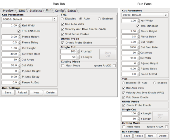
See Axis [DISPLAY] Section or Gmoccapy [DISPLAY] section for information on how to change between the two formats in the <machine_name>.ini files. Alternatively, the user could run the configurator again to select a different option.
Cut Parameters
Name |
Description |
Material |
The top drop down menu is used to manually select the current material cut parameters. If there are no materials in the material file then only the default material will be displayed. |
Kerf Width |
This sets the kerf width for the currently selected material. |
THC Enabled |
This check box enables or disables the THC for the currently selected material. |
Pierce Height |
This sets the pierce height for the currently selected material. |
Pierce Delay |
This sets the pierce delay (in seconds) for the currently selected material. |
Cut Height |
This sets the cut height for the currently selected material. |
Cut Feed Rate |
This sets the cut feed rate for the currently selected material. |
Cut Amps |
This sets the cut amperage for the currently selected material. |
Cut Volts |
This sets the cut voltage for the currently selected material. |
P-Jump Height |
This sets the Puddle Jump height for the currently selected material. |
P-Jump Delay |
This sets the Puddle Jump delay (in seconds) for the currently selected material. |
Pause At End |
This sets the amount of time (in seconds) the torch will stay on at the end of the cut before proceeding with the M5 command to turn off and raise the torch. For more information see Pause At End Of Cut. |
Gas Pressure |
This sets the gas pressure for the currently selected material. |
Cut Mode |
This sets the cut mode for the currently selected material. |
THC
Name |
Modes |
Description |
State |
0, 1, 2 |
Disabled = The THC is permanently off. |
Use Auto Volts |
0, 1 |
Checked = The THC target voltage is ascertained by sampling the arc voltage after the THC Delay has expired. |
Velocity Anti Dive Enable (VAD) |
0, 1, 2 |
Checked = Velocity Anti-Dive is enabled. |
Void Sense Enable |
0, 1 |
Checked = Void sensing is enabled. |
Ohmic Probe
Name |
Description |
Ohmic Probe Enable |
This check box enables or disables the ohmic probe input. |
|
Note
|
If the Ohmic Probe input is disabled, the Ohmic Probe LED will still show the status of the probe input, but the Ohmic Probe results will be ignored. |
Single Cut
Name |
Description |
X Axis Length |
This sets the X axis distance to travel for a single cut. |
Y Axis Length |
This sets the Y axis distance to travel for a single cut. |
Start Cut Button |
Press this button to commence a single cut. |
Cutting Mode
Name |
Description |
Mesh Mode |
This check box will enable or disable mesh mode for the cutting of expanded metal. This check box may be enabled or disabled at any time during normal cutting. Additionally this mode may be enabled or disabled via proper M codes in a running program. |
Ignore Arc OK |
This check box will determine if PlasmaC ignores the Arc OK signal. This check box may be enabled or disabled at any time during normal cutting. Additionally this mode may be enabled or disabled via proper M codes in a running program. |
PowerMax Comms
|
Note
|
This frame is only visible if a PM_PORT is configured in the [PLASMAC] section of the <machine_name>.ini file. |
Name |
Description |
Enable |
This check box will enable or disable the communications to a PowerMax. |
Status |
When PowerMax communications are enabled, this will display one of the following: |
For more information, see the PowerMax Communications section.
Run Settings
Name |
Description |
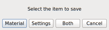
Save |
This button will bring up a dialog box with the following options: |
Reload |
This button will reload all of the displayed settings in the Run Panel, and will re-display the currently selected material. Regardless of the previously saved settings, if PowerMax communications are enabled before pressing Reload, they will remain enabled after. |
New |
This button will allow a new material to be added to the material file. The user will be prompted for a material number and a material name, all other parameters will be read from the currently selected material. Once entered, PlasmaC will reload the material file and display the new material. The Cut Parameters for the new material will then need to be adjusted and saved. |
Delete |
This button is used to delete a material. After pressing it, the user will be prompted for a material number to be deleted, and prompted again to ensure the user is sure. After deletion, the material file will be reloaded and the drop down list will display the default material. |
An example of the Save dialog box is below:
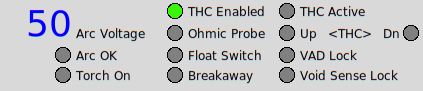
7.1.3. Monitor Panel
The Monitor Panel is used to display the status of various relevant I/O’s. Both Axis and Gmoccapy have similar Monitor Panels.
Name |
Modes |
Description |
Arc Voltage |
0, 1 |
Displays the actual arc voltage. |
Arc OK |
1, 2 |
Indicates the status of the Arc OK signal. |
Torch On |
0, 1, 2 |
Indicates the status of the Torch On output signal. |
THC Enabled |
0, 1, 2 |
Indicates whether the THC will be enabled or disabled during a cut. |
Ohmic Probe |
0, 1, 2 |
Indicates that the probe has sensed the material. |
Float Switch |
0, 1, 2 |
Indicates that the float switch is activated. |
Breakaway |
0, 1, 2 |
Indicates that the torch breakaway sensor is activated. |
THC Active |
0, 1, 2 |
Indicates that the THC is actively controlling the Z axis. |
THC Up |
0, 1, 2 |
Indicates that the THC is commanding the Z axis to raise. |
THC Down |
0, 1, 2 |
Indicates that the THC is commanding the Z axis to lower. |
VAD Lock |
0, 1, 2 |
Indicates that the THC is locked at the current height due to the cut velocity falling below the VAD Threshold percentage set in the Config Panel. |
Void Sense Lock |
0, 1 |
Indicates that the THC is locked due to a void being sensed. |
|
Note
|
The Ohmic Probe LED will show the status of the probe input regardless of whether Ohmic Probe is enabled or disabled. |
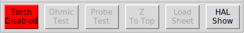
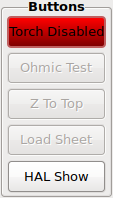
7.1.4. Button Panel
The Button Panel contains buttons useful for the operation of the machine.
Both GUIs have a Torch Enable button which is permanent, all other buttons are user programmable in the <machine_name>.ini file. Axis has five user buttons and Gmoccapy has four user buttons.
Axis button layout:
Gmoccapy button layout:
The Torch Disable/Enable button toggles between Enabling and Disabling the torch. This button defaults to "Torch Disabled" when PlasmaC is first run, and must be clicked to change it to "Torch Enabled" before material cutting can commence.
If "Torch Disabled" is displayed by this button, then running a loaded program will cause the machine to run the cycle without firing the torch. This is sometimes referred to as a "dry run".
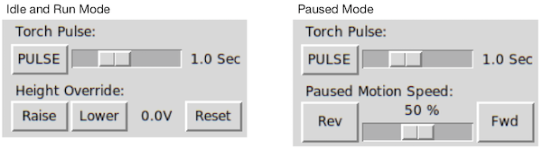
7.1.5. Control Panel
The Control Panel allows the user to pulse the torch for a desired period of time, manually override the height control, and manipulate the machine during paused motion at a desired speed. Both Axis and Gmoccapy are similar except the Gmoccapy Control Panel is integrated into the existing frame containing feed and rapid overrides.
Once the machine is homed, Torch Pulse and Height Override are shown permanently in Idle and Run Modes. Paused Motion Speed will be enabled if the machine enters Paused Mode. Examples of the different states are shown below.
Axis Control Panel:
Gmoccapy Control Panel:
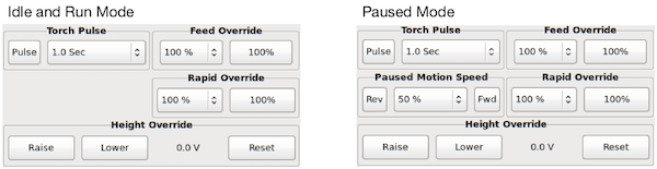
Torch Pulse
Name |
Description |
Pulse |
This button will pulse the torch. |
Pulse Time Slider |
This slider will set the amount of time (in seconds) that the torch remains on when pulsed. |
Height Override
Name |
Description |
Raise |
Each press of this button will raise the height of the torch by the value set by the Height Per Volt field in the Arc frame of the Config Panel. |
Lower |
Each press of this button will lower the height of the torch by the value set by the Height Per Volt field in the Arc frame of the Config Panel. |
Reset |
This button will cancel any manual height override. |
Paused Motion Speed
In the event of a paused program, this interface allows X/Y motion to follow the programmed path in the reverse or forward direction.
Name |
Description |
Rev |
In the event of a paused program, this button will move the machine in reverse along the programmed path until it reaches the last M3 command that was either executed or that PlasmaC was attempting to execute before the program became paused. |
Motion Speed Slider |
This slider will set the percentage of the current Cut Feed Rate shown in the Run Panel’s Cut Parameters section for the currently selected material. |
Fwd |
In the event of a paused program, this button will move the machine forward along the programmed path indefinitely until the program’s end, skipping over M3 commands. |
For advanced recovery from a failed cut see cut recovery.
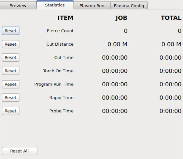
7.1.6. Statistics Panel
The Statistics Panel provides statistics to allow for the tracking of consumable wear and job run times.
These statistics are shown for the current job as well as the running total.
Previous job statistics are reset once the next program is run.
The total values may be reset either individually by clicking the corresponding "Reset" button, or they may all be reset together by clicking "Reset All".
7.1.7. Extras Panel
The Extras Panel provides ten additional user-customizable buttons plus a button to bring up the Conversational dialog box. The Conversational shapes library enables the user to quickly program various simple shapes for quick cutting without the need for CAM software.
See conversational shape library for detailed information on the Conversational feature.
See custom user buttons for detailed information on custom user buttons.
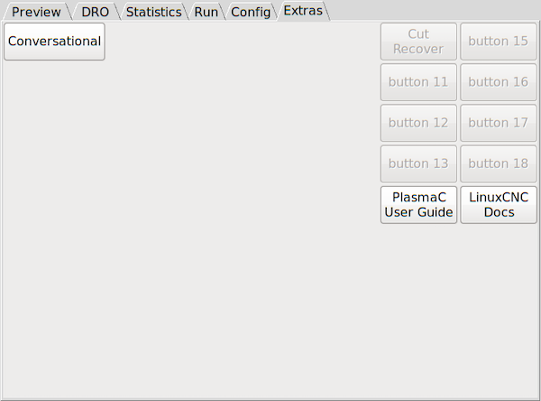
The Extras panel may be disabled by making the appropriate edits in the [DISPLAY] section of the <machine_name>.ini file. This will have no effect on the operation of the PlasmaC software.
To disable the Extras Panel, change:
EMBED_TAB_NAME          = Extras
EMBED_TAB_COMMAND       = gladevcp -c plasmac_wizards -x {XID} -u ./plasmac/plasmac_wizards.py ./plasmac/plasmac_wizards.glade
To:
#EMBED_TAB_NAME          = Extras
#EMBED_TAB_COMMAND       = gladevcp -c plasmac_wizards -x {XID} -u ./plasmac/plasmac_wizards.py ./plasmac/plasmac_wizards.glade
7.2. Mandatory Codes
Aside from the preamble code, postamble code, and X/Y motion code, the only mandatory G-Code syntax for PlasmaC to run a G-Code program is M3 $0 S1 to begin a cut and M5 $0 to end a cut.
If the user is using PlasmaC without multiple tools enabled then it is permissible to use M3 S1 in lieu of M3 $0 S1 to begin a cutting job and M5 in lieu of M5 $0.
7.3. Coordinates
See recommended Z axis settings.
Each time LinuxCNC (PlasmaC) is started Joint homing is required. This allows LinuxCNC (PlasmaC) to establish the known coordinates of each axis and set the soft limits to the values specified in the <machine_name>.ini file in order to prevent the machine from crashing into a hard stop during normal use.
If the machine does not have home switches then the user needs to ensure that all axes are at the home coordinates specified in the <machine_name>.ini file before homing.
If the machine has home switches then it will move to the specified home coordinates when the Joints are homed.
Depending on the machine’s configuration there will either be a Home All button or each axis will need to be homed individually. Use the appropriate button/buttons to home the machine.
As mentioned in the Initial Setup section, it is recommended that the first time PlasmaC is used that the user ensure there is nothing below the torch then jog the Z axis down until it stops at the Z axis MINIMUM_LIMIT then click Touch Off with the Z axis selected to set the Z axis at zero offset. This should not need to be done again.
Before starting a program, jog the Z axis up to approximately 5mm (0.196") from the top of travel (Z Axis MAXIMUM_LIMIT). Leave the Z axis at this position as PlasmaC will control all Z axis motion while running a program, and park the Z Axis in this position when the program completes.
If the user intends to place the material in the exact same place on the table every time, the user could jog the X and Y axes to the machine to the corresponding X0 Y0 position as established by the CAM software and then Touch Off both axes with a zero offset.
If the user intends to place the material randomly on the table then the user must Touch Off the X and Y axes at the appropriate position before starting the program.
7.4. Path Tolerance
The provided RS274NGC_STARTUP_CODE files: metric_startup.ngc and imperial_startup.ngc set the motion blending path tolerance with a G64 command P value to 0.1mm and 0.004" respectively. The P value corresponds to the amount the actual cut path followed by the machine may deviated from the programmed cut path before reducing velocity. If LinuxCNC (PlasmaC) receives an E-stop signal at any stage, the path tolerance will be set to the default (no P value) which will maintain the best possible speed and round corners off as a result. To prevent this, it is recommended that the path tolerance is set by placing the appropriate G64 command and P value in the header of each G-Code file.
For Metric:
G64 P0.1For Imperial:
G64 P0.0047.5. Paused Motion
PlasmaC has the ability to allow the repositioning of the X and Y axes along the current cut path while the G-Code program is paused.
In order to use this feature, LinuxCNC’s Adaptive Feed Control (M52) must be turned on (P1).
To enable Paused Motion The preamble of the G-Code must contain the following line:
M52 P1To turn off Paused Motion at any point, use the following command:
M52 P07.6. Pause At End Of Cut
This feature can be used to allow the arc to "catch up" to the torch position to fully finish the cut. It is usually required for thicker materials and is especially useful when cutting stainless steel.
Using this feature will cause all motion to pause at the end of the cut while the torch is still on. After the dwell time (in seconds) set by the Pause At End parameter in the Cut Parameters section of the Run Panel has expired, PlasmaC will proceed with the M5 command to turn off and raise the torch.
7.7. Multiple Tools
PlasmaC has the ability to allow the use of more than one tool when running a cut program. Multiple tools must be enabled in PlasmaC before they can be used. Valid tools are:
-
Plasma Torch - Used for normal Plasma cutting.
-
Scribe - Used for material engraving.
-
Plasma Torch - Used for spotting (creating dimples to aid in drilling).
If multiple tools are enabled then a LinuxCNC tool number (designated by $n) is required to be in the M3 command to select the correct tool to be used. Examples:
-
M3 $0 S1 will select and start the plasma cutting tool.
-
M3 $1 S1 will select and start the scribe.
-
M3 $2 S1 will select and the plasma spotting tool.
To enable the multiple tools feature the user will need to edit the following line in the <machine_name>_connections.hal file.
from:
setp plasmac.multi-tool 0to:
setp plasmac.multi-tool 1In order to use multiple tools with a scribe, it is necessary for the user to add the X and Y axis offsets to the LinuxCNC tool table. The tool.tbl file is found in the <machine_name> config folder. Tool 0 is assigned to the Plasma Torch and Tool 1 is assigned to the scribe. Tools are selected with a Tn M6 command, and then a G43 H0 command is required to apply the offsets for the selected tool. It is important to note that the LinuxCNC tool table and tool commands only come into play if the user is using a scribe in addition to a plasma torch. For more information, see scribe.
7.8. Velocity Reduction
There is a HAL pin available named motion.analog-out-03 that can be changed in G-Code with the M67 (Synchronized with Motion)/M68 (Immediate) commands. This pin will reduce the velocity to the percentage specified in the command.
It is important to thoroughly understand the difference between Synchronized with Motion and Immediate:
-
M67 (Synchronized with Motion) - The actual change of the specified output (P2 (THC) for example) will happen at the beginning of the next motion command. If there is no subsequent motion command, the output changes will not occur. It is best practice to program a motion code (G0 or G1 for example) right after a M67.
-
M68 (Immediate) - These commands happen immediately as they are received by the motion controller. Since these are not synchronized with motion, they will break blending. This means if these codes are used in the middle of active motion codes, the motion will pause to activate these commands.
Examples:
-
M67 E3 Q0 would set the velocity to 100% of CutFeedRate.
-
M67 E3 Q40 would set the velocity to 40% of CutFeedRate.
-
M67 E3 Q60 would set the velocity to 60% of CutFeedRate.
-
M67 E3 Q100 would set the velocity to 100% of CutFeedRate.
The minimum percentage allowed is 10%, values below this will be set to 10%.
The maximum percentage allowed is 100%, values above this will be set to 100%.
If the user intends to use this feature it would be prudent to add M68 E3 Q0 to both the preamble and postamble of the G-Code program so the machine starts and ends in a known state.
|
Tip
|
Another way of achieving the same result is to use F#<_hal[plasmac.cut-feed-rate] with a multiplier. |
For example:
F[#<_hal[plasmac.cut-feed-rate] * 0.6]|
Important
|
G-CODE THC AND VELOCITY BASED THC ARE NOT ABLE TO BE USED IF CUTTER COMPENSATION IS IN EFFECT; AN ERROR MESSAGE WILL BE DISPLAYED. |
|
Warning
|
If Cut Feed Rate in the Run Panel is set to Zero then PlasmaC will use motion.requested-velocity (as set by a standard Feedrate call in the G-Code) for the THC calculations. This is not recommended as it is not a reliable way of implementing velocity based THC. |
|
Note
|
All references to CutFeedRate refer to the Cut Feed Rate value displayed in the Run Panel. |
7.9. Material Handling
Material handling uses a material file that was created for the machine configuration when the configurator was ran and allows the user to conveniently store known material settings for easy recall either manually or automatically via G Code. The resulting material file is named <machine_name>_material.cfg.
PlasmaC does not require the use of a material file. Instead, the user could change the cut parameters manually from the Run Panel. It is also not required to use the automatic material changes. If the user does not wish to use this feature they can simply omit the material change codes from the G-Code file.
7.9.1. Material File
Material numbers in the materials file do not need to be consecutive nor do they need to be in numerical order.
The following variables are mandatory and an error message will appear if any are not found when the material file is loaded.
-
PIERCE_HEIGHT
-
PIERCE_DELAY
-
CUT_HEIGHT
-
CUT_SPEED
The following variables are optional. If they are not detected or have no value assigned, they will be assigned a value of 0 and no error message will appear.
-
NAME
-
KERF_WIDTH
-
THC
-
PUDDLE_JUMP_HEIGHT
-
PUDDLE_JUMP_DELAY
-
CUT_AMPS
-
CUT_VOLTS
-
PAUSE_AT_END
-
GAS_PRESSURE
-
CUT_MODE
|
Warning
|
It is the responsibility of the operator to ensure that the variables are included if they are a requirement for the G-Code to be run. |
The material file uses the following format:
[MATERIAL_NUMBER_1]
NAME                = name
KERF_WIDTH          = value
THC                 = value (0 = off, 1 = on)
PIERCE_HEIGHT       = value
PIERCE_DELAY        = value
PUDDLE_JUMP_HEIGHT  = value
PUDDLE_JUMP_DELAY   = value
CUT_HEIGHT          = value
CUT_SPEED           = value
CUT_AMPS            = value (for info only unless PowerMax communications is enabled)
CUT_VOLTS           = value (modes 0 & 1 only, if not using auto voltage sampling)
PAUSE_AT_END        = value
GAS_PRESSURE        = value (only used for PowerMax communications)
CUT_MODE            = value (only used for PowerMax communications)
It is possible to add new material, delete material, or edit existing material from the Run Panel. It is also possible to achieve this by using magic comments in a g-Code file.
The material file may be edited with a text editor while LinuxCNC is running. After any changes have been saved, press Reload in the Run Panel to reload the material file.
7.9.2. Manual Material Handling
For manual material handling, the user would manually select the material from the materials list in the Run Panel before starting the G-Code program. In addition to selecting materials with materials list in the Run Panel, the user could use the MDI to change materials with the following command:
M190 PnThe following code is the minimum code necessary to have a successful cut using the manual material selection method:
F#<_hal[plasmac.cut-feed-rate]>
M3 $0 S1
.
.
M5 $0|
Note
|
Manual material handling will restrict the user to only one material for the entire job. |
7.9.3. Automatic Material Handling
For automatic material handling, the user would add commands to their G-Code file which will enable PlasmaC to change the material automatically.
The following codes may be used to allow PlasmaC to automatically change materials:
-
M190 Pn - Changes the currently displayed material to material number n.
-
M66 P3 L3 Q1 - Adds a small delay (1 second in this example) to wait for PlasmaC to confirm that it successfully changed materials.
-
F#<_hal[plasmac.cut-feed-rate]> - Sets the cut feed rate to the feed rate shown in the Cut Parameter section of the Run Panel.
For automatic material handling, the codes MUST be applied in the order shown. If a G-Code program is loaded which contains one or more material change commands then the first material will be displayed in the Run Panel as the program is loading. The following code is the minimum code necessary to have a successful cut using the automatic material selection method:
M190 Pn
M66 P3 L3 Q1
F#<_hal[plasmac.cut-feed-rate]>
M3 $0 S1
.
.
M5 $0
7.9.4. Materialverter
This application is used to convert existing tool tables into PlasmaC material files. It can also create a material file from manual user input to entry fields.
At this stage the only conversions available are to tool tables from SheetCam and Fusion360.
SheetCam tool tables are complete and the conversion is fully automatic. The SheetCam tool file must be in the SheetCam .tools format.
Fusion360 tool tables do not have all of the required fields so the user will be prompted for missing parameters. The Fusion360 tool file must be in the Fusion360 .json format.
If the user has a format from a different CAM software they would like converted, create a New Topic in the PlasmaC forum section of the LinuxCNC forum to request this addition.
Materialverter may be run from a GUI file manager by double clicking on materialverter.py in the user’s configuration directory or may be run by entering the following command into a terminal window:
python ~/linuxcnc/configs/<machine_name>/materialverter.pyThis will bring up the Materialverter dialog:
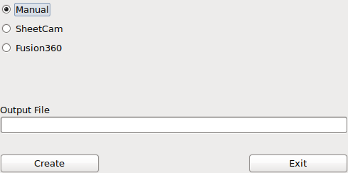
Select one of:
-
Manual - to manually create a new material file.
-
SheetCam - to convert a SheetCam tool file.
-
Fusion360 - to convert a Fusion360 tool file.
For SheetCam only, select whether the user requires a metric or imperial output file.
To convert:
-
Select the Input File to be converted.
-
Select the Output File to write to. This would normally be ~/linuxcnc/configs/<machine_name>_material.cfg. If necessary, the user could select a different file and hand edit the <machine_name>_material.cfg file.
-
Click Create/Convert and the new material file will be created.
For both a Manual creation or a Fusion360 conversion, a dialog will show with all available parameters displayed for input. Any entry marked with *** is mandatory and all other entries are optional depending on the user’s configuration needs.
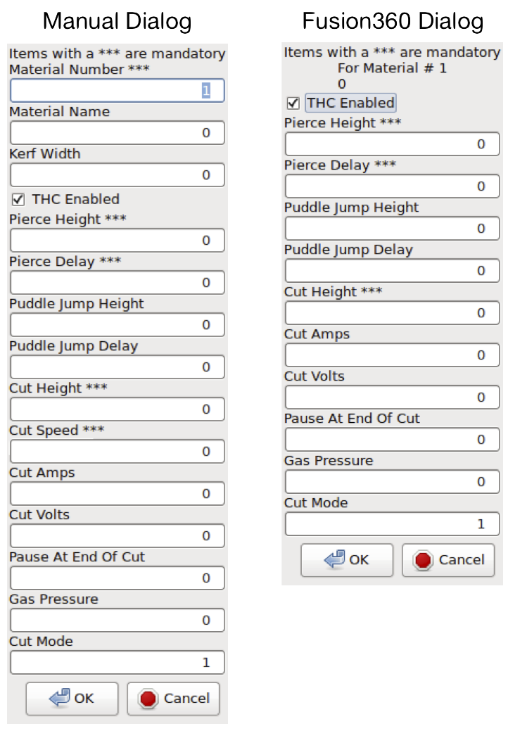
|
Note
|
If the user selects ~/linuxcnc/configs/<machine_name>_material.cfg and the file already exists, it will be overwritten. |
7.9.5. Materials Adding And Editing Via G-Code
It is possible to add new materials or edit existing materials by using "magic comments" in a G-Code file.
Formatting rules are:
-
The entire comment must be in parentheses.
-
The beginning of the magic comment must be: (o=
-
The equals sign must immediately follow each parameter with no space.
-
The mandatory parameters must be in the magic comment (nu and na are not required for option 0).
-
There can be any number and type of magic comments in a G-Code file with the exception of option 0. If more than one option 0 comment is found in the G-Code file then only the last one found will be used.
-
If option 0 is to be used in addition to option 1 and/or option 2 then the option 0 comment must be the last one in the G-Code file.
The options are:
Option |
Description |
0 |
Creates a temporary default material. |
1 |
Adds a new material if the number specified does not exist. |
2 |
Overwrites an existing material if the number specified exists. |
Mandatory parameters are:
Name |
Description |
o |
Selects the option to be used. |
nu |
Sets the material number (not required for option 0). |
na |
Sets the material name (not required for option 0). |
ph |
Sets the pierce height. |
pd |
Sets the pierce delay. |
ch |
Sets the cut height. |
fr |
Sets the feed rate. |
Optional parameters are:
Name |
Description |
kw |
Sets the kerf width. |
th |
Sets the THC status (0=disabled, 1=enabled). |
ca |
Sets the cut amps. |
cv |
Sets the cut voltage. |
pe |
Sets the pause at end delay. |
gp |
Sets the gas pressure (PowerMax). |
cm |
Sets the cut mode (PowerMax). |
jh |
Sets the puddle jump height. |
jd |
Sets the puddle jump delay. |
A complete example:
(o=1, nu=2, na=5mm Mild Steel 40A, ph=3.1, pd=0.1, ch=0.75, fr=3000, kw=0.5, th=1, ca=45, cv=110, pe=0.1, gp=5, cm=1, jh=0, jd=0)7.10. THC (Torch Height Controller)
The THC can be controlled from the THC frame of the Run Panel.
The THC can also be enabled or disabled directly from the G-Code program provided that THC is not disabled in the THC section of the Run Panel.
PlasmaC uses a control voltage which is dependent on the state of the Use Auto Volts checkbox in the Run Panel:
-
If Use Auto Volts is checked then the actual cut voltage is sampled after the cut begins. To allow the arc voltage to stabilize, PlasmaC waits for the amount of time displayed in the Delay field of the THC section of the config panel before sampling the voltage. The sampled voltage is then used as the target voltage to adjust the height of the torch.
-
If Use Auto Volts is not checked then the voltage displayed as Cut Volts in the Cut Parameters section of the Run Panel is used as the target voltage to adjust the height of the torch.
The THC does not become active until the velocity reaches 99.9% of the CutFeedRate.
G-Code THC
THC may be disabled and enabled directly from G-Code, provided the THC is not disabled in the Run Panel, by setting or resetting the motion.digital-out-02 pin with the M-Codes M62-M65:
-
M62 P2 will disable THC (Synchronized with Motion)
-
M63 P2 will enable THC (Synchronized with Motion)
-
M64 P2 will disable THC (Immediately)
-
M65 P2 will enable THC (Immediately)
It is important to thoroughly understand the difference between Synchronized with Motion and Immediate:
-
M62 and M63 (Synchronized with Motion) - The actual change of the specified output (P2 (THC) for example) will happen at the beginning of the next motion command. If there is no subsequent motion command, the output changes will not occur. It is best practice to program a motion code (G0 or G1 for example) right after a M62 or M63.
-
M64 and M65 (Immediate) - These commands happen immediately as they are received by the motion controller. Since these are not synchronized with motion, they will break blending. This means if these codes are used in the middle of active motion codes, the motion will pause to activate these commands.
Velocity Based THC
If the cut velocity falls below a percentage of CutFeedRate (as defined by the VAD Threshold % value in the THC frame of the Config Panel) the THC will be locked until the cut velocity returns to at least 99.9% of CutFeedRate. This will be made apparent by the THC Velocity Lock indicator illuminating in the Monitor Panel.
Velocity based THC prevents the torch height being changed when velocity is reduced for a sharp corner or a small hole.
It is important to note that Velocity Reduction affects the Velocity Based THC in the following ways:
-
If Velocity Reduction is invoked in the middle of the cut, the THC will be locked.
-
The THC will remain locked until the velocity reduction is canceled by returning it to a value that is above the VAD Threshold, and the torch actually reaches 99.9% of the CutFeedRate.
7.11. Cutter Compensation
LinuxCNC (PlasmaC) has the ability to automatically adjust the cut path of the current program by the amount specified in Kerf Width of the selected material’s Cut Parameters. This is helpful if the G-Code is programmed to the nominal cut path and the user will be running the program on different thickness materials to help ensure consistently sized parts.
To use cutter compensation the user will need to use G41.1, G42.1 and G40 with the kerf width HAL pin:
-
G41.1 D#<_hal[plasmac_run.kerf-width-f]> : offsets torch to the left of the programmed path
-
G42.1 D#<_hal[plasmac_run.kerf-width-f]> : offsets torch to the right of the programmed path
-
G40 turns the cutter compensation off
|
Important
|
IF CUTTER COMPENSATION IS IN EFFECT G-CODE THC, VELOCITY BASED THC AND OVERCUT ARE NOT ABLE TO BE USED; AN ERROR MESSAGE WILL BE DISPLAYED. |
7.12. Initial Height Sense (IHS) Skip
IHS may be skipped in one of two different ways:
-
If the THC is disabled then the IHS skip will occur if the start of the cut is less than Skip IHS distance from the last successful probe.
-
If the THC is enabled then the IHS skip will occur if the start of the cut is less than Skip IHS distance from the end of the last cut.
A value of zero for Skip IHS will disable IHS skipping.
Any errors encountered during a cut will disable IHS skipping for the next cut if Skip IHS is enabled.
7.13. Probing
Probing may be done with either ohmic sensing or a float switch. It is also possible to combine the two methods, in which case the float switch will provide a fallback to ohmic probing.
If the machine’s torch does not support ohmic probing, the user could have a separate probe next to the torch. In this case the user would extend the probe below the torch. The probe must NOT extend more than the minimum Cut Height below the torch and the Z axis offset distance needs to be entered as the ohmic-probe-offset in the Config Panel.
Probing setup is done in the Probing frame of the Config Panel. Probing speed is controlled in the Motion frame of the Config Panel.
PlasmaC can probe at the full Z axis velocity so long as the machine has enough movement in the float switch to absorb any overrun. If the machine’s float switch travel is suitable, the user could set the Probe Height to near the Z axis MINIMUM_LIMIT and do all probing at full speed.
Some float switches can exhibit a large switching hysteresis which shows up in the probing sequence as an excessive time to complete the final probe up.
-
This time may be decreased by changing the speed of the final probe up.
-
This speed defaults to 0.001mm (0.000039") per servo cycle.
-
It is possible to increase this speed by up to a factor of 10 by adding the following line to the <machine_name>_connections.hal file:
setp plasmac.probe-final-speed nwhere n is a value from 1-10. It is recommended to keep this value as low as possible.
Using this feature will change the final height slightly and will require thorough probe testing to confirm the final height.
This speed value affects ALL probing so if the user uses ohmic probing and the user changes this speed value then the user will need to probe test to set the require offset to compensate for this speed change as well as the float travel.
The reliability of this feature will only be as good as the repeatability of the float switch.
|
Note
|
Probe Height refers to the height above the Z axis MINIMUM_LIMIT. |
7.14. Cut Types
PlasmaC allows two different cut modes:
-
Pierce and Cut - runs the loaded G-Code program to pierce then cut.
-
Pierce Only - converts the loaded G-Code program and then runs the program to pierce the material at the M3 S1 or M3 $0 S1 command positions only. Scribe (M3 $1 S1) and Spotting (M3 $2 S1) commands will be ignored and no pierce will take place in those locations.
Pierce Only mode is useful for thick materials which may produce enough dross on the material surface from piercing to interfere with the torch while cutting. This enables the entire sheet to be pierced and cleaned off before cutting.
This also enables near-end-of-life consumables to be used for piercing and then they can be swapped out for good consumables to be used while cutting.
There are two ways of enabling this feature:
-
Utilize the default custom user button to toggle between the cut types.
-
Adding the following line to the G-Code program before the first cut to enable Pierce Only mode for the current file:
#<pierce-only> = 1If using a custom user button is utilized then PlasmaC will automatically reload the file when the cut type is toggled.
7.15. Hole Cutting - Intro
It is recommended that any holes to be cut have a diameter no less than one and a half times the thickness of the material to be cut.
It is also recommended that holes with a diameter of less than 32mm (1.26") are cut at 60% of the feed rate used for profile cuts. This should also lock out THC due to velocity constraints.
PlasmaC can utilize G-Code commands usually set by a CAM Post Processor (PP) to aid in hole cutting or if the user does not have a PP or the user’s PP does not support these methods then PlasmaC can automatically adapt the G-Code to suit. This automatic mode is disabled by default.
There are three methods available for improving the quality of small holes:
-
Velocity Reduction - Reducing the velocity to approximately 60% of the CutFeedRate.
-
Arc Dwell (Pause At End) - Keeping the torch on for a short time at the end of the hole while motion is stopped to allow the arc to catch up.
-
Overcut - Turning the torch off at the end of the hole then continue along the path.
|
Note
|
If both Arc Dwell and Overcut are active at the same time then Overcut will take precedence. |
|
Important
|
OVERCUT IS NOT ABLE TO BE USED IF CUTTER COMPENSATION IS IN EFFECT; AN ERROR MESSAGE WILL BE DISPLAYED. |
7.16. Hole Cutting
G-Code commands can be set up by either by a CAM Post Processor (PP) or by hand coding.
Hole Cutting Velocity Reduction
If cutting a hole requires a reduced velocity then the user would use the following command to set the velocity: M67 E3 Qnn where nn is the percentage of the velocity desired. For example, M67 E3 Q60 would set the velocity to 60% of the current material’s CutFeedRate.
See the Velocity Based THC section.
Sample code:
G21 (metric)
G64 P0.005
M52 P1 (allow paused motion)
F#<_hal[plasmac.cut-feed-rate]> (feed rate from cut parameters)
G0 X10 Y10
M3 $0 S1 (start cut)
G1 X0
M67 E3 Q60 (reduce feed rate to 60%)
G3 I10 (the hole)
M67 E3 Q0 (restore feed rate to 100%)
M5 $0 (end cut)
G0 X0 Y0
M2 (end job)
Arc Dwell (Pause At End)
This method can be invoked by setting the Pause At End parameter in the Cut Parameters frame of the Run Panel.
Overcut
The torch can be turned off at the end of the hole by setting the motion.digital-out-03 pin with the M-Codes M62 (Synchronized with Motion) or M64 (Immediate). After turning the torch off it is necessary to allow the torch to be turned on again before beginning the next cut by resetting the motion.digital-out-03 pin with the M-Codes M63 or M65, this will be done automatically by the PlasmaC G-Code parser if it reaches an M5 command without seeing a M63 P3 or M65 P3.
After the torch is turned off the hole path will be followed for a default length of 4mm (0.157"). This distance may be specified by adding #<oclength> = n to the G-Code file.
-
M62 P3 will turn the torch off (Synchronized with Motion)
-
M63 P3 will allow the torch to be turned on (Synchronized with Motion)
-
M64 P3 will turn the torch off (Immediately)
-
M65 P3 will allow the torch to be turned on (Immediately)
It is important to thoroughly understand the difference between Synchronized with motion and Immediate:
-
M62 and M63 (Synchronized with Motion) - The actual change of the specified output (P2 (THC) for example) will happen at the beginning of the next motion command. If there is no subsequent motion command, the output changes will not occur. It is best practice to program a motion code (G0 or G1 for example) right after a M62 or M63.
-
M64 and M65 (Immediate) - These commands happen immediately as they are received by the motion controller. Since these are not synchronized with motion, they will break blending. This means if these codes are used in the middle of active motion codes, the motion will pause to activate these commands.
Sample code:
G21 (metric)
G64 P0.005
M52 P1 (allow paused motion)
F#<_hal[plasmac.cut-feed-rate]> (feed rate from cut parameters)
G0 X10 Y10
M3 $0 S1 (start cut)
G1 X0
M67 E3 Q60 (reduce feed rate to 60%)
G3 I10 (the hole)
M62 P3 (turn torch off)
G3 X0.8 Y6.081 I10 (continue motion for 4mm)
M63 P3 (allow torch to be turned on)
M67 E3 Q0 (restore feed rate to 100%)
M5 $0 (end cut)
G0 X0 Y0
M2 (end job)
7.17. Hole Cutting - Automatic
PlasmaC has the ability to automatically modify the G-Code to reduce the velocity and/or apply Overcut which can be useful when cutting holes.
The default hole size for PlasmaC hole sensing is 32mm (1.26"). It is possible to change this value with the following command in a G-Code file:
-
#<h_diameter> = nn - To set a diameter (nn) in the same units system as the rest of the G-Code file.
The default velocity for PlasmaC small holes is 60% of the current feed rate. It is possible to change this value with the following command in a G-Code file:
-
#<h_velocity> = nn - to set the percentage (nn) of the current feed rate required.
PlasmaC Hole Sensing is disabled by default. It can be enabled/disabled by using the following G-Code parameters to select the desired hole sensing mode:
-
#<holes> = 0 - Causes PlasmaC to disable hole sensing if it was previously enabled.
-
#<holes> = 1 - Causes PlasmaC to reduce the speed of holes less than 32mm (1.26") to 60% of CutFeedRate.
-
#<holes> = 2 - Causes PlasmaC to Overcut the hole in addition to the velocity changes in setting 1.
-
#<holes> = 3 - Causes PlasmaC to reduce the speed of holes less than 32mm (1.26") and arcs less than 16mm (0.63") to 60% of CutFeedRate.
-
#<holes> = 4 - Causes PlasmaC to Overcut the hole in addition to the velocity change in setting 3.
Arc Dwell (Pause At End)
This feature can be used in addition to setting the desired hole sensing mode via the appropriate G-Code parameter by setting the Pause At End parameter in the Cut Parameters frame of the Run Panel.
Overcut
If Hole Sensing modes 2 or 4 are active, PlasmaC will overcut the hole in addition to the velocity changes associated with modes 1 and 3.
The default overcut length for PlasmaC hole sensing is 4mm (0.157"). It is possible to change this value with the following command in a G-Code file:
-
#<oclength> = nn to specify an overcut length (nn) in the same units system as the rest of the G-Code file.
Sample code:
G21 (metric)
G64 P0.005
M52 P1 (allow paused motion)
F#<_hal[plasmac.cut-feed-rate]> (feed rate from cut parameters)
#<holes> = 2 (overcut for holes)
#<oclength> = 6.5 (optional, 6.5mm overcut length)
G0 X10 Y10
M3 $0 S1 (start cut)
G1 X0
G3 I10 (the hole)
M5 $0 (end cut)
G0 X0 Y0
M2 (end job)|
Note
|
It is OK to have multiple and mixed hole commands in a single G-Code file. |
7.18. Single Cut
A single cut is a single unidirectional cutting move often used to cut a sheet into smaller pieces prior to running a G-Code program.
The machine needs to be homed before commencing a single cut.
A single cut will commence from the machines current X/Y position.
Automatic Single Cut
This is the preferred method. The parameters for this method are entered in the Run Panel.
-
Jog to the required X/Y start position.
-
Set required Cut Feed Rate in Cut Parameters of the Run Panel.
-
Enter the length of the cut along the X and/or Y axes.
-
Press the Start Cut button and the cut will commence.
Pendant Single Cut
If the machine is equipped with a pendant that can start and stop the spindle plus jog the X and Y axes, the user can manually perform a single cut.
-
Jog to the required X/Y start position.
-
Set the required feed rate with the Jog Speed slider.
-
Start the cut process by starting the spindle.
-
After probing the torch will fire.
-
When the Arc OK is received the machine can be jogged along the cut line using the jog buttons.
-
When the cut is complete stop the spindle.
-
The torch will turn off and the Z axis will return to the starting position.
Manual Single Cut In Axis
-
Jog to the required X/Y start position.
-
Set the required feed rate with the Jog Speed slider.
-
Start the procedure by pressing F9.
-
After probing the torch will fire.
-
When the Arc OK is received the machine can be jogged along the cut line using the jog keys.
-
When the cut is complete press F9 or Esc.
-
The torch will turn off and the Z axis will return to the starting position.
|
Note
|
If the torch flames out during cutting, the user must still press F9 or Esc to end the cut. This clears the Z offsets and returns the torch to the starting position. |
Manual Single Cut In Gmoccapy
If the user wishes to use the keyboard jogging keys then enable keyboard shortcuts in the Hardware tab of the Settings page, otherwise the GUI jog buttons must be used.
-
Jog to the required X/Y start position.
-
Set the required feed rate with the Jog Speed slider.
-
Enter MDI mode.
-
Start the procedure by entering M3 S1.
-
Enter Manual mode.
-
After probing the torch will fire.
-
When the Arc OK is received the machine can be jogged along the cut line using the GUI jog buttons (or jog keys if keyboard shortcuts are enabled).
-
When the cut is complete press Esc.
-
The torch will turn off and the Z axis will return to the starting position.
|
Note
|
If the torch flames out during cutting, the user must still press F9 or Esc to end the cut. This clears the Z offsets and returns the torch to the starting position. |
7.19. Mesh Mode (Expanded Metal Cutting)
PlasmaC is capable of cutting of expand (mesh) metal provided the machine has a pilot arc torch and it is capable of Constant Pilot Arc (CPA) mode.
Mesh Mode disables the THC and also ignores a lost Arc OK signal during a cut. It can be selected by checking the Mesh Mode check button in the Cutting Mode section of the Run Panel.
If the machine has RS485 communications enabled with a Hypertherm PowerMax plasma cutter, selecting Mesh Mode will disable the Cut Mode spinbutton in the Cut Parameters section of the Run Panel and it will select cut mode 2 (CPA). When Mesh Mode is disabled, the Cut Mode spinbutton will be re-enabled and the original cut mode will be restored.
It is also possible to start a Mesh Mode cut without receiving an Arc OK signal by checking the Ignore Arc OK check button in the Cutting Mode section of the Run Panel.
Both Mesh Mode and Ignore Arc OK can be enabled/disabled at any time during a job.
7.20. Ignore Arc OK
Ignore Arc OK mode disables the THC, will begin a cut without requiring an Arc OK signal, and will ignore a lost Arc OK signal during a cut.
This mode can be selected by:
-
Checking the Ignore Arc OK check button in the Cutting Mode section of the Run Panel.
-
Setting HAL pin motion.digital-out-01 to 1 via G-Code.
-
M62 P1 will enable Ignore Arc OK (Synchronized with Motion)
-
M63 P1 will disable Ignore Arc OK (Synchronized with Motion)
-
M64 P1 will enable Ignore Arc OK (Immediately)
-
M65 P1 will disable Ignore Arc OK (Immediately)
-
It is important to thoroughly understand the difference between Synchronized with motion and Immediate:
-
M62 and M63 (Synchronized with Motion) - The actual change of the specified output (P2 (THC) for example) will happen at the beginning of the next motion command. If there is no subsequent motion command, the output changes will not occur. It is best practice to program a motion code (G0 or G1 for example) right after a M62 or M63.
-
M64 and M65 (Immediate) - These commands happen immediately as they are received by the motion controller. Since these are not synchronized with motion, they will break blending. This means if these codes are used in the middle of active motion codes, the motion will pause to activate these commands.
This mode may also be used in conjunction with Mesh Mode if the user doesn’t require an Arc OK signal to begin the cut.
Both Mesh Mode and Ignore Arc OK can be enabled/disabled at any time during a job.
7.21. Cut Recovery
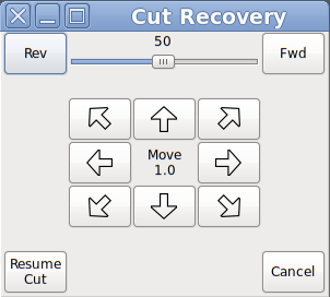
This feature will produce a dialog box that will allow the torch to be moved away from the cut path during a paused motion event in order to position the torch over a scrap portion of the material being cut so that the cut restarts with a minimized arc-divot. This feature is only available from a user-programmed button (named Cut-Recovery by default) in the Extras panel and may only be clicked while motion is paused.
It is preferable to make torch position adjustments from the point at which paused motion occurred, however if moving along the cut path is necessary prior to setting the new start point, the user may use the paused motion controls (Rev, Fwd, and a jog-speed slider) at the top of the dialog box. Once the user is satisfied with the positioning of the torch along the cut path, moving off the cut path is achieved by pressing the direction buttons. Each press of the direction button will move the torch a distance equivalent to the Kerf Width parameter of the currently selected material.
The moment the torch has been moved off the cut path, the paused motion controls (Rev, Fwd, and a jog-speed slider) at the top of the dialog box will become disabled.
Once the torch position is satisfactory, press Resume Cut or the GUI’s Resume button (Pause symbol) and the cut will resume from the new position and travel the shortest distance to the original paused motion location. The dialog box will close when the torch returns to the original paused motion location.
Pressing Cancel (or the X in the title bar) will cause the torch to move back to where it was positioned when the motion became paused and the dialog box will close.
7.22. Conversational Shape Library
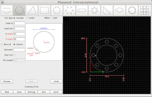
The Conversational Shape Library consists of several basic shapes and functions to assist the user with generating quick G-Code at the machine to cut simple shapes quickly. This feature is started by clicking the Conversational button found in the Extras tab.
|
Note
|
The Conversational Library is not meant to be a CAD/CAM replacement as there are limitations to what can be achieved. |
Blank entries in the shape input boxes will use the current setting at the time the G-Code was generated. For example, if X start was left blank then the current X axis position would be used.
All lead-ins and lead-outs are arcs except for:
-
Small holes
-
Stars
The cut order will occur in the same order as the shape was built.
Pressing Return on the keyboard while editing parameters will automatically show the preview of the shape if there are enough parameters entered to create the shape. Clicking any of the available check boxes will do the same.
The button functions are as follows:
Name |
Description |
New |
Removes the current G-Code file and load a blank G-Code file. |
Save |
Opens a dialog allowing the current shape to be saved as a G-Code file. |
Settings |
Allows the changing of the global settings. |
Quit |
Closes the Conversational Panel. All edits will be discarded. |
Send |
Closes the Conversational Panel and load the current shape into LinuxCNC (PlasmaC). If the last edit was not added then it will be discarded. |
Preview |
Displays a preview of the current shape provided the required information is present. |
Continue |
This button is used for lines and arcs only. Allows another segment to be added to the current segment/segments. |
Add |
Stores the current shape into the current job. |
Undo |
Reverts to the previously stored state. If there have been no edits since the last store, it will stay at the current state. |
If there is a G-Code file loaded in LinuxCNC (PlasmaC) when the Conversational Panel is opened, that code will be imported into the conversational as the first shape of the job. If this code is not required then it can be removed by pressing the New button.
|
Note
|
All distances are in machine units relative to the current User Coordinate System and all angles are in degrees. |
7.22.1. Settings
Global settings for the shape library can be set by pressing the Settings button in the Conversational Panel. This will display all of the available settings parameters that are used for G-Code program creation. These include:
-
Preamble
-
Postamble
-
Origin (Center or Bottom Left)
-
Lead-in length
-
Lead-out length
-
Small hole diameter
-
Small hole speed
-
Window Size
Any internal circle that has a diameter less than Small hole diameter is classified as a small hole and will have a straight lead-in with a length that is the lesser of either the radius of the hole or the specified lead-in length. It will also have its feed rate set to Small hole speed.
Pressing the Save button will save all the settings as displayed and will change the window size to the displayed size.
After saving the user may press Quit or they may click on any shape to start the Conversational process.
7.22.2. Lines And Arcs

Lines and arcs have an additional option in that they may be strung together to create a complex shape.
There are two line types and three arc types available:
-
Line given a start point and an end point.
-
Line given a start point, length, and angle.
-
Arc given a start point, way point, and end point.
-
Arc given a start point, end point, and radius.
-
Arc given a start point, length, angle, and radius.
To use lines and arcs:
-
Select Lines and Arcs.
-
Select the type of line or arc to create.
-
Enter the desired parameters.
-
Press Preview to see the shape.
-
If satisfied with the shape press Continue.
-
Change the line or arc type if needed and continue this procedure until the shape is complete.
-
Press Send to send the G-Code file to LinuxCNC (PlasmaC) for cutting.
If the user wishes to create a closed shape, they will need to create any required lead-in as the first segment of the shape. If a lead-out is required it will need to be the last segment of the shape.
|
Note
|
At this stage there is no automatic option for a lead-in/lead-out creation if the shape is closed. |
7.22.3. Single Shape
The following shapes are available for creation:
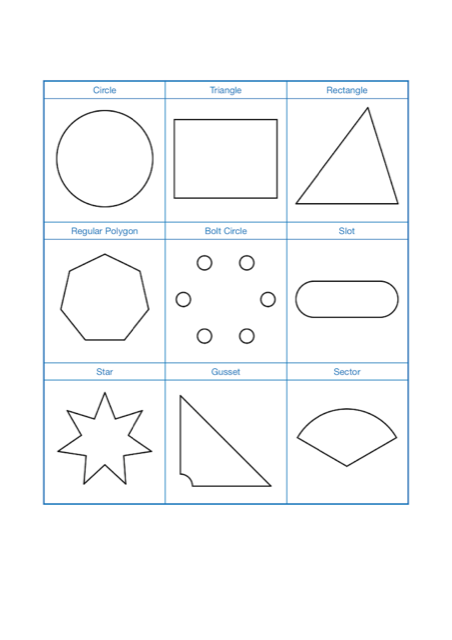
To create a shape:
-
Select the shape to create. The available parameters will be displayed.
-
Enter the appropriate values and press Preview to display the shape.
-
If the shape is not correct, edit the values and press Preview and the new shape will be displayed. Repeat until satisfied with the shape.
-
Press Add to add the shape to the G-Code file.
-
Press Send to send the G-Code file to LinuxCNC (PlasmaC) for cutting.
7.22.4. Group Of Shapes
Multiple shapes can be added together to create a complex group.
The cut order of the group is determined by the order in which the individual shapes are added to the group.
Once a shape is added to the group it cannot be edited or removed.
Groups cannot have shapes removed, only added to.
To create a group of shapes:
-
Create the first shape as in Single Shape.
-
Press Add and the shape will be added to the group.
-
If the user wishes to add another version of the same shape then edit the required parameters and press Add when satisfied with the shape.
-
If the user wishes to add a different shape, select that shape and create it as in Single Shape.
-
Repeat until all the required shapes to complete the group have been added.
-
Press Send to send the G-Code file to LinuxCNC (PlasmaC) for cutting.
7.22.5. Rotate

The rotate feature will rotate the current code displayed in the Preview tab, this can be a single shape, a group or an imported G-Code file.
Arrays created via Conversational may be rotated, however arrays that have been imported cannot be rotated.
Rotation will not work on G-Code that is mathematically calculated, the values need to be specified.
-
Create a shape, a group, or use the imported G-Code file.
-
Press Rotate to open the rotate dialog.
-
Enter the appropriate values in the rotate dialog and press Preview to display the rotated code.
-
If the rotation is not correct, edit the values and press Preview and the new rotated code will be shown. Repeat until satisfied with the rotated code.
-
Press Add to complete the procedure.
-
Press Send to send the G-Code file to LinuxCNC (PlasmaC) for cutting.
7.22.6. Array

An array can be created from a shape, a group or an imported G-Code file.
Arrays created with Conversational may be arrayed but imported arrays cannot be arrayed.
The cut order of an array is from the left column to the right column, starting at the bottom row and ending at the top row.
-
Create a shape, a group, or use the imported G-Code file.
-
Press Array to open the array dialog.
-
Enter the appropriate values in the array dialog and press Preview to display the array.
-
If the array is not correct, edit the values and press Preview and the new array will be shown. Repeat until satisfied with the array.
-
Press Add to complete the procedure.
-
Press Send to send the G-Code file to LinuxCNC (PlasmaC) for cutting.
7.22.7. Saving A Job
The current job displayed in the Preview Panel may be saved at any time by using the bottom Save button. If the G-Code has been sent to LinuxCNC (PlasmaC) and the Conversational dialog box has closed, the user may still save the G-Code file from the GUI. Alternatively, the user could click the Conversational button in the Extras tab which will reload the job, at which time they can press the Save button.
7.23. Scribe
A scribe may be operated by PlasmaC in addition to the plasma torch. This ability is disabled by default so as not to adversely affect existing configurations. To enable scribing, see the Multiple Tools section for guidance in editing the <machine_name>_connections.hal file.
Using a scribe requires the use of the LinuxCNC tool table. Tool 0 is assigned to the plasma torch and Tool 1 is assigned to the scribe. The scribe X and Y axes offsets from the plasma torch need to be entered into the LinuxCNC tool table. This is done by editing the tool table via the main GUI, or by editing the tool.tbl file in the <machine_name> configuration directory. This will be done after the scribe can move to the work piece to help determine the appropriate offset.
The plasma torch offsets for X and Y will always be zero. The tools are selected by the Tn M6 command followed by a G43 H0 command which is required to apply the offsets. The tool is then started with a M3 $n S1 command. For n, use 0 for torch cutting or 1 for scribing.
If the user has not yet assigned the HAL pins for the scribe in the Configurator then they will need to do so by invoking the reconfigure mode of the Configurator.
There are two HAL output pins used to operate the scribe, the first pin is used to arm the scribe which moves the scribe to the surface of the material. After the Arm Delay has elapsed, the second pin is used to start the scribe. After the On Delay has elapsed, motion will begin.
Using PlasmaC after enabling the scribe requires the selection of either the torch or the scribe in each G-Code file as a LinuxCNC tool.
The next step is to open the tool table editor in the GUI or edit tool.tbl in the <machine_name> configuration directory and enter the X and Y axes offsets. These are the distances in X and Y the scribe is away from the torch as measured from the center of the torch nozzle. In most cases, if the user is standing at the front of the machine and the scribe is to the right of the torch, a positive X offset would be required. Similarly, if the scribe is to the rear of the torch, a positive Y offset would be required. The offsets for the torch should always be zero.
The final step is to set the scribe delays required:
-
Arm Delay - allows time for the scribe to descend to the surface of the material.
-
On Delay - allows time for the scribe to start before motion begins.
Save the parameters in the Config tab.
After the above directions are completed, the scribe may be tested manually by issuing a M3 $1 S1 command in the MDI input. The user may find it helpful to use this method to scribe a small divot and then try to pulse the torch in the same location to align the offsets between the scribe and the torch.
To use the scribe from G-Code:
...
M52 P1 (paused motion on)
F#<_hal[plasmac.cut-feed-rate]>
T1 M6 (select scribe)
G43 H0 (apply offsets for current tool)
M3 $1 S1 (start the scribe)
.
M5 $1 (stop the scribe)
.
T0 M6 (select torch)
G43 H0 (apply offsets for current tool)
G0 X0 Y0 (parking position)
M5 $-1 (end all)
It is a good idea to switch back to the torch at the end of the program before the final rapid parking move so the machine is always in the same state at idle.
The user can switch between the torch and the scribe any number of times during a program by using the appropriate G-Codes.
Issuing M3 S1 (without $n) will cause the machine to behave as if an M3 $0 S1 had been issued and issuing M5 (without $n) will cause the machine to behave as if an M5 $0 had been issued. This will control the torch firing by default in order to provide backward compatibility for previous G-Code files.
|
Warning
|
If there is an existing manual tool change parameter set in the <machine_name>.hal file then PlasmaC will convert it to an automatic tool change. |
7.24. Spotting
To achieve spotting to mark the material prior to drilling etc., PlasmaC can pulse the torch for a short duration to mark the spot to drill.
Spotting can be configured by following these steps:
-
Set the arc voltage threshold in the Spotting section of the Config Panel. Setting the voltage threshold to zero will cause the delay timer to begin immediately upon starting the torch. Setting the voltage threshold above zero will cause the delay timer to begin when the arc voltage reaches the threshold voltage.
-
Set the Time On in the Spotting section of the Config Panel. When the Time On timer has elapsed, the torch will turn off. Times are adjustable from 0 to 9999 milliseconds.
The torch is then turned on in G-Code with the M3 $2 S1 command which selects the plasma torch as a spotting tool.
To enable spotting, see multiple tools.
LinuxCNC (PlasmaC) requires some motion between any M3 and M5 commands. For this reason, a minimal movement at a high speed is required to be programmed.
An example G-Code is:
G21 (metric)
F99999 (high feed rate)
.
.
G0 X10 Y10
M3 $2 S1 (spotting on)
G91 (relative distance mode)
G1 X0.000001
G90 (absolute distance mode)
M5 $2 (spotting off)
.
.
G0 X0 Y0
G90
M2|
Note
|
The high feed rate of 99999 is to ensure that the motion is at the machine’s highest feed rate. |
|
Important
|
SOME PLASMA CUTTERS WILL NOT BE SUITABLE FOR THIS FEATURE. IT IS RECOMMENDED THAT THE USER CARRY OUT SOME TEST SPOTTING TO ENSURE THAT THE PLASMA CUTTER IS CAPABLE OF UTILIZING THIS FEATURE. |
7.25. Hypertherm PowerMax Communications
Communications can be established with a Hypertherm PowerMax plasma cutter that has a RS485 port. This feature enables the setting of Cut Mode, Cutting Amperage and Gas Pressure automatically from the Cut Parameters of the material file.
If Gas Pressure is set to Zero then the PowerMax will automatically calculate the required pressure from the Cut Mode, Cut Current, torch type, and torch length.
Changing the cutting mode will set the gas pressure to zero causing the machine to use its automatic gas pressure mode.
The maximum and minimum values of these parameters are read from the plasma cutter and the related spin-buttons in the Cut Parameters are then limited by these values. Gas pressure can not be changed from zero until communications have been established.
This feature is enabled by setting the correct port name for the PM_PORT variable in the [PLASMAC] section of the <machine_name>.ini file. If the PM_PORT variable is not set in the <machine_name>.ini file then the widgets associated with this feature will not be visible.
Example showing enabling the Hypertherm PowerMax Communications on USB0:
[PLASMAC]
PM_PORT = /dev/ttyusb0
If the user is unsure of the name of the port, there is a python script in the configuration directory that will show all available ports and can also be used to test communications with the plasma unit prior to enabling this feature in the PlasmaC GUI.
To use the test script enter the following command into a terminal window:
python ~/<user_name>/linuxcnc/configs/<the_user_config>/pmx_test.pyThe gas pressure units display (psi or bar) is determined by the data received during initial setup of the communication link and is then shown next to the Gas Pressure spinbutton on the Run Panel.
The PowerMax machine will go into remote mode after communications have been established and may only be controlled remotely (via the PlasmaC GUI) at this point. The connection can be validated by observing the PowerMax display.
To switch the PowerMax back to local mode the user can either:
-
Disable PowerMax Comms from the Run panel
-
Close LinuxCNC which will put the PowerMax into local mode during shutdown.
-
Turn the PowerMax off for 30 seconds and then power it back on.
|
Tip
|
If PowerMax communications is active then selecting Mesh Mode will automatically select CPA mode on the PowerMax unit. |
|
Note
|
To use the PowerMax communications feature it is necessary to have the python pyserial module installed. If pyserial is not installed an error message will be displayed. |
To install pyserial, enter the following command into a terminal window:
sudo apt install python-serialA typical connection diagram is shown in the appendix of this document as well as confirmed working interfaces.
7.26. Error Messages
There are a number of error messages printed by PlasmaC to inform the user of faults as they occur. The messages can be split into two groups, Critical and Warning.
7.26.1. Critical Errors
Critical Errors will cause the running program to pause, and the operator will need to clear the cause of the error before proceeding.
If the error was received during cutting then forward or reverse motion is allowed while the machine is paused to enable the user to reposition the machine prior to resuming the cut.
When the error is cleared the program may be resumed.
These errors indicate the corresponding sensor was activated during cutting:
-
breakaway switch activated program is paused
-
float switch activated program is paused
-
ohmic probe activated program is paused
These errors indicate the corresponding sensor was activated before probing commenced:
-
ohmic probe detected before probing program is paused
-
float switch detected before probing program is paused
-
breakaway switch detected before probing program is paused
The Arc OK signal was lost during cutting motion, before the M5 command was reached:
-
valid arc lost program is paused
The Z axis reached the bottom limit before the work piece was detected:
-
bottom limit reached while probing down program is paused
The work piece is too high for any safe rapid removes:
-
material too high for safe traverse program is paused
One of these values in Cut Parameters in the Run Panel is invalid (For example: if they are set to zero):
-
invalid pierce height or invalid cut height or invalid cut volts program is paused
No arc has been detected after attempting to start the number of times indicated by Arc Start Attempts in the Config Panel:
-
no arc detected after <n>d start attempts program is paused
-
no arc detected after <n>d start attempts manual cut is stopped
THC has caused the bottom limit to be reached while cutting:
-
bottom limit reached while THC moving down program is paused
THC has caused the top limit to be reached while cutting:
-
top limit reached while THC moving up program is paused
7.26.2. Warning errors
Warning errors will not pause a running program and are informational only.
These errors indicate the corresponding sensor was activated before a probe test commenced:
-
ohmic probe detected before probing probe test aborted
-
float switch detected before probing probe test aborted
-
breakaway switch detected before probing probe test aborted
This indicates that probe contact was lost before probing up to find the zero point:
-
probe trip error while probing
This indicates the bottom limit was reached during a probe test:
-
bottom limit reached while probe testing
This indicates that the safe height has been reduced due to THC raising the Z axis during cutting:
-
safe traverse height has been reduced
This indicates that the value for the Arc Voltage was invalid (NAN or INF) when PlasmaC launched.
-
invalid arc-voltage-in
7.27. Updating PlasmaC
PlasmaC update notices are posted at: https://forum.linuxcnc.org/plasmac/37233-plasmac-updates
Users are strongly encouraged to create a Username and subscribe to the above thread to receive update notices.
7.27.1. Standard Update
For a standard ISO installation, LinuxCNC will only be updated when a new minor release has been released. PlasmaC will then automatically update its configuration the first time it is run after a LinuxCNC update.
LinuxCNC is normally updated by entering the following commands into a terminal window (one at a time):
sudo apt update
sudo apt dist-upgrade
7.27.2. Continuous Update
Enhancements and bug fixes will not be available on a standard installation until a new minor release of LinuxCNC has been released. If the user wishes to update whenever a new PlasmaC version has been pushed, they could use the LinuxCNC Buildbot repository rather than the standard LinuxCNC repository by following the instructions at: http://buildbot.linuxcnc.org/
8. PlasmaC Advanced Topics
8.1. Custom User Buttons
There are buttons available in the PlasmaC GUI that are programmable by adding commands in the <machine_name>.ini file. The number of buttons varies by whether the user chose to use PlasmaC with Axis or Gmoccapy.
Five buttons are available in the main window of the Axis GUI, numbered 1-5 from left to right.
Four buttons are available in the main window of the Gmoccapy GUI, numbered 1-4 from top to bottom.
There are an additional ten buttons available in the Extras panel, numbered 10-19 from top left to bottom right.
All <machine_name>.ini file settings for the buttons are found in the [PLASMAC] section.
8.1.1. Button Names
The text that appears on the button is set the following way:
BUTTON_n_NAME = HAL ShowWhere n is the button number and HAL Show is the text.
For text on multiple lines in the Axis GUI, split the text with a \
BUTTON_n_NAME = HAL\Show8.1.2. Button Code
Buttons can run External Commands, G-Code or any of six special functions, Toggle HAL Pin, Probe Test, Ohmic Test, Cut Type, Change Consumables, or Touch Off X & Y.
In addition to this, buttons 10-19 in the Extras panel can run the special functions Cut Recovery, Load G-Code program as well as display a custom image instead of the button name.
External Commands
To run an external command, the command is preceded by a % character.
BUTTON_n_CODE = %halshowG-Code
To run G-Code, just enter the code to be run.
BUTTON_n_CODE = G0 X100To run an existing subroutine.
BUTTON_n_CODE = o<my_subroutine> call<machine_name>.ini file variables can be entered by using {} (a space must be placed after the })
BUTTON_n_CODE = G0 X{JOINT_0 HOME} Y1
BUTTON_n_CODE = G53 G0 Z[{AXIS_Z MAX_LIMIT} - 1.001]
Multiple codes can be run by separating the codes with a \ symbol. The exception is the special commands which are required to be a single command per button.
BUTTON_n_CODE = G0 X0 Y0 \ G1 X5 \ G1 Y5External commands and G-Code may be mixed on the same button.
BUTTON_n_CODE = %halshow \ g0x.5y.5 \ %halmeterToggle HAL Pin
The following code will allow the user to use a button to invert the current state of a HAL bit pin (this code is required to be used as a single command and may only control one HAL bit pin per button):
BUTTON_n_CODE = toggle-halpin my-hal-pin-nameAfter setting the code, upon clicking, the button will turn green, invert the pin state, and stay "latched" until it is clicked again. Clicking again will return the button to the original color and invert the pin state.
Probe Test
PlasmaC will begin a probe and when the material is detected, the Z axis will rise to the Pierce Height currently displayed in the Cut Parameters section of the Run Panel. PlasmaC will then wait in this state for the time specified (in seconds) before returning the Z axis to the starting position. An example of a 30 second delay is below.
BUTTON_n_CODE = probe-test 30Ohmic Test
PlasmaC will enable the Ohmic Probe Enable output signal and if the Ohmic Probe input is sensed, the LED indicator in the Monitor Panel will light. The main purpose of this is to allow a quick test for a shorted torch tip.
BUTTON_n_CODE = ohmic-testCut Type
This button if selected will toggle between the two cut types, Pierce and Cut (default cutting mode) or Pierce Only.
BUTTON_n_CODE = cut-typeChange Consumables
Pressing this button moves the torch to the specified coordinates when the machine is paused to allow the user easy access to change the torch consumables.
Valid entries are Xnnn Ynnn Fnnn. Feed Rate (F) is mandatory and at least one of the X or Y coordinates are required.
The X and Y coordinates are in absolute machine coordinates. If X or Y are missing then the current coordinate for that axis will be used.
There are three methods to return to the previous coordinates:
-
Press the Change Consumables button again - the torch will return to the original coordinates and the machine will wait in this position for the user to resume the program.
-
Resume the program - the torch to return to the original coordinates and the program will resume.
-
Stop the program - the torch to return to the original coordinates and the program will abort.
BUTTON_n_CODE = change-consumables X10 Y10 F1000Touch Off X & Y
Buttons 1-19 are capable of touching off (zeroing) the X and Y axes and moving Z to an appropriate height for the start of a g-code program run.
If the user is using the Axis GUI, they may also add a command to run a routine that will reload the program, clear the live plot, and re-zoom the preview window. This will allow the user to easily see where the new zero coordinates are with respect to the currently loaded G-Code program.
To set the X and Y axes to zero:
G10 L20 P0 X0 Y0To move the Z axis away from the MAXIMUM_LIMIT by a small amount to prepare for cutting (5.0mm in the following example):
G53 G0 Z[{AXIS_Z MAX_LIMIT} - 5.0]To refresh the preview window (Axis GUI only):
%halcmd setp axisui.refresh 1Combined to perform all 3 tasks:
G10 L20 P0 X0 Y0 \ G53 G0 Z[{AXIS_Z MAX_LIMIT} - 5.0] \ %halcmd setp axisui.refresh 1Cut Recovery
Pressing this button brings up the cut recovery dialog which will allow the user to move the torch off of the cut path to find a suitable piece of material to restart the cut from. This function is only available from the Extras panel and the button is only valid while paused.
BUTTON_n_CODE = cut-recoveryLoad
Buttons 10-19 in the Extras Panel are able to load a G-Code program by using the following format:
BUTTON_n_CODE = load path/to/G-Code.ngcThe path is relative to the directory specified by PROGRAM_PREFIX in the <machine_name>.ini file. This is usually ~/linuxcnc/nc_files. For example: If the user’s G-Code file was in a subdirectory of the PROGRAM_PREFIX directory named plasma then the entry would be plasma/G-Code.ngc.
8.1.3. Button Image
Buttons 10-19 in the Extras Panel are able to display an image instead of text. If an image is specified then this will take precedence and the image will be displayed instead of the button name.
BUTTON_n_IMAGE = path/to/image.pngThe path is relative to the configuration directory, so if the image was in a sub-directory of the configuration directory named images then the entry would be images/image.png.
All images are displayed in a 60 x 60 format.
8.2. Test Panel
There is a directory named test in the machine’s configuration folder which has a simple Test Panel and associated python file which can be used to test the example configuration as referenced in the <machine_name>.ini file.
If the user wishes to use this in a sim configuration then the user will need to create a link to this directory and edit the <machine_name>.ini file to suit.
8.3. Tuning Void Sensing
Void sensing may be further tuned by adjusting the required number of consecutive times that the threshold has been exceeded before applying the void lock to the THC.
The parameter for adjusting this is named plasmac.kerf-errors-max and the default value is 2. To change this value, add the parameter and the required value to the <machine_name>_connections.hal file. The following example would set the required number of consecutive times to exceed the threshold to 3:
setp plasmac.kerf-error-max 38.4. Lost Arc Delay
Some plasma power sources/machine configurations may lose the Arc OK signal either momentarily during a cut, or permanently near the end of a cut causing PlasmaC to pause the program and report a "valid arc lost" error. There is a HAL pin named plasmac.arc-lost-delay that may be used to set a delay (in seconds) that will prevent a paused program/error if the lost Arc OK signal is regained, or the M5 command is reached before the set delay period expires.
The following code would set a delay of 0.1 seconds:
setp plasmac.arc-lost-delay 0.1It is recommended that the user set this parameter in the <machine_name>_connections.hal file.
This setting should only be used if the user experiences the above symptoms. It should also be noted that the user could use the appropriate Ignore Arc OK G-Code commands to achieve a similar result.
8.5. PlasmaC State Outputs
PlasmaC has a HAL pin named plasmac.state-out which can be used to interface with user-coded components to provide PlasmaC’s current state.
The different states PlasmaC could encounter are as follows:
State |
Description |
0 |
IDLE |
1 |
PROBE_HEIGHT |
2 |
PROBE_DOWN |
3 |
PROBE_UP |
4 |
ZERO_HEIGHT |
5 |
PIERCE_HEIGHT |
6 |
TORCH_ON |
7 |
ARC_OK |
8 |
PIERCE_DELAY |
9 |
PUDDLE_JUMP |
10 |
CUT_HEIGHT |
11 |
CUT |
12 |
PAUSE_AT_END |
13 |
SAFE_HEIGHT |
14 |
MAX_HEIGHT |
15 |
FINISH |
16 |
TORCHPULSE |
17 |
PAUSED_MOTION |
18 |
OHIMC_TEST |
19 |
PROBE_TEST |
20 |
SCRIBING |
21 |
CONSUMABLE_CHANGE_ON |
22 |
CONSUMABLE_CHANGE_OFF |
23 |
CUT_RECOVERY_ON |
24 |
CUT_RECOVERY_OFF |
25 |
DEBUG |
The DEBUG state is for testing purposes only and will not normally be encountered.
9. Appendix
9.1. Example Configurations
There are example configuration files for both the Axis and Gmoccapy GUIs which use the PlasmaC HAL component to simulate plasma cutting machines.
-
metric_plasmac.ini
-
imperial_plasmac.ini
If the user has copied any example configs to the ~/linuxcnc/configs directory then they are able to be updated by running the Configurator in Update mode. This will replace any copied PlasmaC system file with a link to the latest version the user has updated to.
9.2. NGC Samples
There are some sample G-Code files in nc_files/plasmac.
9.3. Change Type Of LinuxCNC Installation
Before changing the type of installation, the existing PlasmaC installation needs to be updated to the latest version. If PlasmaC is not at the latest version then changing the installation type may corrupt the existing PlasmaC configuration.
It is recommended that a backup copy of the existing PlasmaC configuration is made before proceeding.
If the user has changed the type of LinuxCNC installation from a Package installation to a Run In Place or vice versa the user will need to run the Configurator from the new LinuxCNC installation directory, NOT from the ~/linuxcnc/configs directory. This is required to reset the file links for the correct installation type.
Enter the following command into a terminal window do one of the following:
Reset to a new Package installation:
python /usr/share/doc/linuxcnc/examples/sample-configs/by_machine/plasmac/configurator.pyReset to a new Run In Place installation:
python ~/linuxcnc-dev/configs/by_machine/plasmac/configurator.py9.4. PlasmaC Specific G-Codes
Description |
Code |
Begin cut |
M3 $0 S1 |
End cut |
M5 $0 |
Begin scribe |
M3 $1 S1 |
End scribe |
M5 $1 |
Begin center spot |
M3 $2 S1 |
End center spot |
M5 $2 |
End all the above |
M5 $-1 |
Select a material |
M190 Pn |
Wait for material change confirmation |
M66 P3 L3 Qn |
Set feed rate from material |
F#<_hal[plasmac.cut-feed-rate]> |
Enable Ignore Arc OK |
M62 P1 (synchronized with motion) |
Disable Ignore Arc OK |
M63 P1 (synchronized with motion) |
Disable THC |
M62 P2 (synchronized with motion) |
Enable THC |
M63 P2 (synchronized with motion) |
Disable Torch |
M62 P3 (synchronized with motion) |
Enable Torch |
M63 P3 (synchronized with motion) |
Set velocity to a percentage of feed rate |
M67 E3 Qn (synchronized with motion) |
Cutter compensation - left of path |
G41.1 D#<_hal[plasmac_run.kerf-width-f]> |
Cutter compensation - right of path |
G42.1 D#<_hal[plasmac_run.kerf-width-f]> |
Cutter compensation off |
G40 |
Cut holes at 60% feed rate |
#<holes> = 1 |
Cut holes at 60% feed rate, |
#<holes> = 2 |
Cut holes and arcs at 60% feed rate |
#<holes> = 3 |
Cut holes and arcs at 60% feed rate, |
#<holes> = 4 |
Specify hole diameter for |
#<h_diameter> = n (n is the diameter, use the same units system as the rest of the G-Code file) |
Specify hole velocity for |
#<h_velocity> = n (n is the percentage, set the percentage of the current feed rate) |
Specify overcut length |
#<oclength> = n (n is the length, use the same units system as the rest of the G-Code file) |
Specify pierce-only mode |
#<pierce-only> = n (n is the mode, 0=normal cut mode, 1=pierce only mode) |
Create or edit materials. |
mandatory parameters: |
9.5. PlasmaC Gcode Examples
Description |
Example |
Select material and do a normal cut |
M190 P3 |
Set velocity to 100% of CutFeedRate |
M67 E3 Q0 or M67 E3 Q100 |
Set velocity to 60% of CutFeedRate |
M67 E3 Q60 |
Set velocity to 40% of CutFeedRate |
M67 E3 Q40 |
Cut a hole with 60% reduced speed using velocity setting |
G21 (metric) |
Cut a hole with 60% reduced speed using the #<holes> command |
G21 (metric) |
Cut a hole with overcut using torch disable |
G21 (metric) |
Cut a hole with overcut using the #<holes> command |
G21 (metric) |
Cut a hole with 6.5mm overcut using the #<holes> command |
G21 (metric) |
Select scribe and select torch at end of scribing |
. |
Hole center spotting. |
(Requires a small motion command or nothing happens) |
Create temporary default material |
(o=1, nu=2, na=5mm Mild Steel 40A, ph=3.1, pd=0.1, ch=0.75, fr=3000) |
Edit material, if not existing create a new one |
(o=3, nu=2, na=5mm Mild Steel 40A, ph=3.1, pd=0.1, ch=0.75, fr=3000, kw=1.0) |
9.6. Mesa THCAD
The Mesa THCAD is the most common way of obtaining the arc voltage from a plasma cutter. The THCAD may be used for parallel port configurations or for configurations using Mesa Electronics hardware.
The preferred method is to setup the required parameters for the THCAD in the <machine_name>_connections.hal file.
9.6.1. Parallel Port Config
An example parallel port config using a software encoder.
THCAD jumper settings UNIPOLAR and F/64
|
Note
|
If the user’s computer has good latency then they may be able to use F/32 |
loadrt encoder num_chan=1
setp encoder.0.counter−mode 1
setp encoder.0.position−scale -1
addf encoder.update-counters base-thread
addf encoder.capture-position servo-thread
net arc-voltage-raw parport.1.pin-04-in encoder.0.phase-A
The user then needs to note that the Arc Voltage HAL Pin entry in the PlasmaC Configurator will be:
encoder.0.velocity9.6.2. Mesa 7i96 Config:
An example Mesa 7i96 config using the onboard hardware encoder is shown below. Other Mesa hardware will be similar but with a different board identifiers.
THCAD jumper settings UNIPOLAR and F/32
setp  hm2_7i96.0.encoder.00.scale -1
setp  hm2_7i96.0.encoder.00.filter 1
setp  hm2_7i96.0.encoder.00.counter-mode 1
The user then needs to note that the Arc Voltage HAL Pin entry in the PlasmaC Configurator will be:
hm2_7i96.0.encoder.00.velocity|
Note
|
There is a lowpass filter available which may be useful if using a THCAD and there is a lot of noise on the returned arc voltage. |
9.6.3. Obtaining The Divider Ratio
THCAD-10
If connecting to a plasma CNC port then the divider ratio is selected from the plasma machine.
If connecting to the plasma machines full arc voltage then a common setup is to use a 1 Megohm resistor from arc negative to THCAD negative and a 1 Megohm resistor from arc positive to THCAD positive. This gives a full scale reading of 210V. The THCAD can handle over-voltages up to 500V indefinitely.
To get the divider ratio use (R1 + R2 + 100000) / 100000. An example with the above resistance values would be: (1000000 + 1000000 + 100000) / 100000, giving a ratio of 21.
|
Important
|
IF THE USER IS USING A HF START PLASMA POWER SUPPLY THEN EACH OF THESE RESISTANCES SHOULD BE MADE UP OF SEVERAL HIGH VOLTAGE RESISTORS. |
THCAD-300
This is connected to the plasma machines full arc voltage and the divider ratio = 1
9.6.4. Calibration Values
These values are used to obtain starting values for Voltage Offset and Voltage Scale in the Config Panel.
They are located on the rear of the THCAD via a calibration sticker showing:
    THCAD-nnn

 0V  121.1 kHz
 5V  925.3 kHz
or similar values, these are the frequencies generated by the THCAD for 0 volts and full scale volts respectively.
The Voltage Scale and Voltage Offset can now be calculated manually, as shown below, or by using this online calulator.
Voltage Scale
Use the formula:
Divider_Ratio / ((THCAD_Full_Scale_Frequency - THCAD_0V_Frequency) / THCAD_Frequency_Divider / THCAD_Full_Scale_Voltage)This result will be used for setting Voltage Scale in the Config Panel when setting up the configuration.
THCAD-10 example with a jumper setting of F/32 would be:
21 / ((925300 - 121100) / 32 / 10) = 0.00835613For the calculation above, 21 comes from the divider calculation example, 32 is the jumper setting F/32, and 10 is the full scale reading of the THCAD card itself.
THCAD-300 example would be:
1 / ((925300 - 121100) / 32 / 300) = 0.01193732For our calculation above, 1 is the divider ratio, 32 is the jumper setting F/32, and 300 is the full scale reading of the THCAD card itself.
Voltage Offset
Use the formula:
THCAD_0V_Frequency / THCAD_Frequency_DividerThis result will be used for setting Voltage Offset in the Config Panel when setting up the configuration.
The THCAD-10 and THCAD-300 examples above would be:
121100 / 32 = 3784.3759.7. RS485 Connections
Hypertherm RS485 Wiring Diagram (wire colors inside the Hypertherm in parentheses):
Connection at Machine Pin # |
Connection at Breakout Board |
1 - Tx+ (Red) |
->RXD+ |
2 - Tx- (Black) |
->RXD- |
3 - Rx+ (Brown) |
->T/R+ |
4 - Rx- (White) |
->T/R- |
5 - GND (Green) |
->GND |
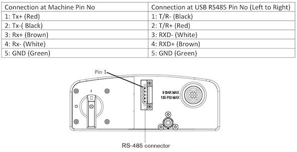
RS485 interfaces that are known to work:
DTECH DT-5019 USB to RS485 converter adapter:
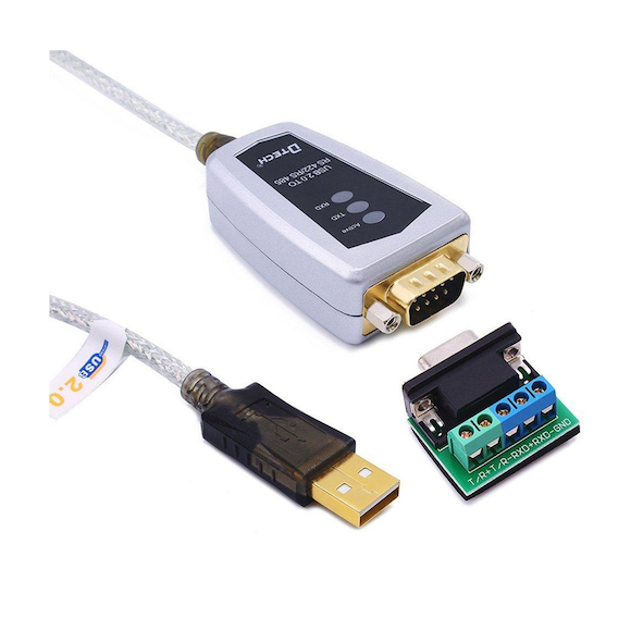
The following is necessary to convert a motherboard Serial connection or Serial card (RS232) to RS485:
DTECH RS232 to RS485 converter:

Serial card example (Sunnix SER5037A PCI Card shown with Breakout Board):
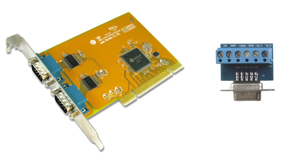
9.8. Arc OK With A Reed Relay
An effective and very reliable method of obtaining an Arc OK signal from a plasma power supply without a CNC port is to mount a reed relay inside a non-conductive tube and wrap and secure three turns of the work lead around the tube.
This assembly will now act as a relay that will switch on when current is flowing through the work lead which only occurs when a cutting arc has been established.
This will require that PlasmaC be operated in Mode 1 rather than Mode 0. See the INI File and PlasmaC Modes sections for more information.
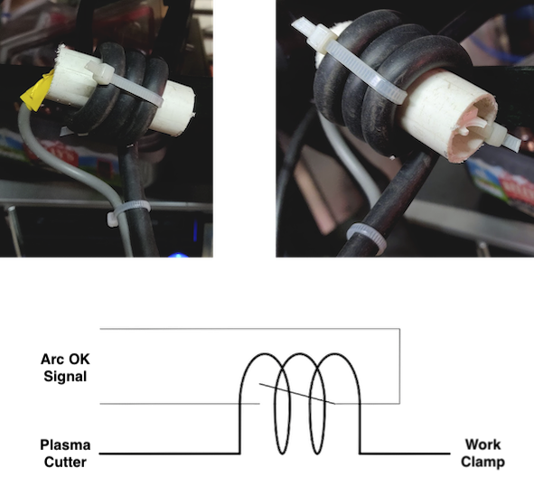
10. Support
Online help and support is available from the PlasmaC section of the LinuxCNC Forum.
The user can create a compressed file containing the complete machine configuration to aid in fault diagnosis by pressing following the directions in the backup section. The resulting file is suitable for attaching to a post on the LinuxCNC Forum to help the community diagnose specific issues.