1. Overview
The LinuxCNC G Code language is based on the RS274/NGC language. The G Code language is based on lines of code. Each line (also called a block) may include commands to do several different things. Lines of code may be collected in a file to make a program.
A typical line of code consists of an optional line number at the beginning followed by one or more words. A word consists of a letter followed by a number (or something that evaluates to a number). A word may either give a command or provide an argument to a command. For example, G1 X3 is a valid line of code with two words. G1 is a command meaning move in a straight line at the programmed feed rate to the programmed end point, and X3 provides an argument value (the value of X should be 3 at the end of the move). Most LinuxCNC G Code commands start with either G or M (for General and Miscellaneous). The words for these commands are called G codes and M codes.
The LinuxCNC language has no indicator for the start of a program. The Interpreter, however, deals with files. A single program may be in a single file, or a program may be spread across several files. A file may demarcated with percents in the following way. The first non-blank line of a file may contain nothing but a percent sign, %, possibly surrounded by white space, and later in the file (normally at the end of the file) there may be a similar line. Demarcating a file with percents is optional if the file has an M2 or M30 in it, but is required if not. An error will be signaled if a file has a percent line at the beginning but not at the end. The useful contents of a file demarcated by percents stop after the second percent line. Anything after that is ignored.
The LinuxCNC G Code language has two commands (M2 or M30), either of which ends a program. A program may end before the end of a file. Lines of a file that occur after the end of a program are not to be executed. The interpreter does not even read them.
2. Format of a line
A permissible line of input code consists of the following, in order, with the restriction that there is a maximum (currently 256) to the number of characters allowed on a line.
-
an optional block delete character, which is a slash /.
-
an optional line number.
-
any number of words, parameter settings, and comments.
-
an end of line marker (carriage return or line feed or both).
Any input not explicitly allowed is illegal and will cause the Interpreter to signal an error.
Spaces and tabs are allowed anywhere on a line of code and do not change the meaning of the line, except inside comments. This makes some strange-looking input legal. The line G0X +0. 12 34Y 7 is equivalent to G0 x+0.1234 Y7, for example.
Blank lines are allowed in the input. They are to be ignored.
Input is case insensitive, except in comments, i.e., any letter outside a comment may be in upper or lower case without changing the meaning of a line.
3. Block Delete
The optional block delete character the slash / when placed first on a line can be used by some user interfaces to skip lines of code when needed. In Axis the key combination Alt-m-/ toggles block delete on and off. When block delete is on any lines starting with the slash / are skipped.
4. Line Number
A line number is the letter N followed by an unsigned integer. Line numbers may be repeated or used out of order, although normal practice is to avoid such usage. Line numbers may also be skipped, and that is normal practice. A line number is not required to be used, but must be in the proper place if used.
5. Word
A word is a letter other than N followed by a real value.
Words may begin with any of the letters shown in the following Table. The table includes N for completeness, even though, as defined above, line numbers are not words. Several letters (I, J, K, L, P, R) may have different meanings in different contexts. Letters which refer to axis names are not valid on a machine which does not have the corresponding axis.
| Letter | Meaning |
|---|---|
A |
A axis of machine |
B |
B axis of machine |
C |
C axis of machine |
D |
Tool radius compensation number |
F |
Feed rate |
G |
General function (See table Modal Groups) |
H |
Tool length offset index |
I |
X offset for arcs and G87 canned cycles |
J |
Y offset for arcs and G87 canned cycles |
K |
Z offset for arcs and G87 canned cycles. |
Spindle-Motion Ratio for G33 synchronized movements. |
|
M |
Miscellaneous function (See table Modal Groups) |
N |
Line number |
P |
Dwell time in canned cycles and with G4. |
Key used with G10. |
|
Q |
Feed increment in G73, G83 canned cycles |
R |
Arc radius or canned cycle plane |
S |
Spindle speed |
T |
Tool selection |
U |
U axis of machine |
V |
V axis of machine |
W |
W axis of machine |
X |
X axis of machine |
Y |
Y axis of machine |
Z |
Z axis of machine |
6. Number
The following rules are used for (explicit) numbers. In these rules a digit is a single character between 0 and 9.
-
A number consists of (1) an optional plus or minus sign, followed by (2) zero to many digits, followed, possibly, by (3) one decimal point, followed by (4) zero to many digits - provided that there is at least one digit somewhere in the number.
-
There are two kinds of numbers: integers and decimals. An integer does not have a decimal point in it; a decimal does.
-
Numbers may have any number of digits, subject to the limitation on line length. Only about seventeen significant figures will be retained, however (enough for all known applications).
-
A non-zero number with no sign as the first character is assumed to be positive.
Notice that initial (before the decimal point and the first non-zero digit) and trailing (after the decimal point and the last non-zero digit) zeros are allowed but not required. A number written with initial or trailing zeros will have the same value when it is read as if the extra zeros were not there.
Numbers used for specific purposes in RS274/NGC are often restricted to some finite set of values or some to some range of values. In many uses, decimal numbers must be close to integers; this includes the values of indexes (for parameters and carousel slot numbers, for example), M codes, and G codes multiplied by ten. A decimal number which is supposed be close to an integer is considered close enough if it is within 0.0001 of an integer.
7. Parameters (Variables)
The RS274/NGC language supports parameters - what in other programming languages would be called variables. There are several types of parameter of different purpose and appearance, each described in the following sections. The only value type supported by parameters is floating-point; there are no string, boolean or integer types in G-code like in other programming languages. However, logic expressions can be formulated with boolean operators ( AND, OR, XOR, and the comparison operators EQ,NE,GT,GE,LT,LE), and the MOD, ROUND, FUP and FIX operators support integer arithmetic.
Parameters differ in syntax, scope, behavior when not yet initialized, mode, persistence and intended use.
- Syntax
-
There are three kinds of syntactic appearance:
-
numbered - #4711
-
named local - #<localvalue>
-
named global - #<_globalvalue>
-
- Scope
-
The scope of a parameter is either global, or local within a subroutine. Subroutine parameters and local named variables have local scope. Global named parameters and numbered parameters starting from number 31 are global in scope. RS274/NGC uses lexical scoping - in a subroutine only the local variables defined therein, and any global variables are visible. The local variables of a calling procedure are not visible in a called procedure.
- Behavior of uninitialized parameters
-
-
unitialized global parameters, and unused subroutine parameters return the value zero when used in an expression.
-
unitialized named parameters signal an error when used in an expression.
-
- Mode
-
Most parameters are read/write and may be assigned to within an assignment statement. However, for many predefined parameters this does not make sense, so they are are read-only - they may appear in expressions, but not on the left-hand side of an assignment statement.
- Persistence
-
When LinuxCNC is shut down, volatile parameters lose their values. All parameters except numbered parameters in the current persistent range
[The range of persistent parameters may change as development progresses. This range is currently 5161- 5390. It is defined in the _required_parameters array in file the src/emc/rs274ngc/interp_array.cc .]
are volatile. Persistent parameters are saved in the .var file and restored to their previous values when LinuxCNC is started again. Volatile numbered parameters are reset to zero. - Intended Use
-
-
user parameters:: numbered parameters in the range 31..5000, and named global and local parameters except predefined parameters. These are available for general-purpose storage of floating-point values, like intermediate results, flags etc, throughout program execution. They are read/write (can be assigned a value).
-
subroutine parameters - these are used to hold the actual parameters passed to a subroutine.
-
numbered parameters - most of these are used to access offsets of coordinate systems.
-
system parameters - used to determine the current running version. They are read-only.
-
7.1. Numbered Parameters
A numbered parameter is the pound character # followed by an integer between 1 and 5399. The parameter is referred to by this integer, and its value is whatever number is stored in the parameter.
A value is stored in a parameter with the = operator; for example:
#3 = 15 (set parameter 3 to 15)
A parameter setting does not take effect until after all parameter values on the same line have been found. For example, if parameter 3 has been previously set to 15 and the line #3=6 G1 X#3 is interpreted, a straight move to a point where X equals 15 will occur and the value of parameter 3 will be 6.
The character takes precedence over other operations, so that, for example, #1+2 means the number found by adding 2 to the value of parameter 1, not the value found in parameter 3. Of course, [1+2] does mean the value found in parameter 3. The character may be repeated; for example #2 means the value of the parameter whose index is the (integer) value of parameter 2.
The interpreter maintains a number of read-only parameters for a loaded tool:
-
1-30 - Subroutine local parameters of call arguments. These parameters are local to the subroutine. See the O Codes Section.
-
1-5000 - G-Code user parameters. These parameters are global in the G Code file.
-
5061-5070 - Result of G38.2 Probe (X Y Z A B C U V W)
-
5161-5169 - G28 Home for (X Y Z A B C U V W)
-
5181-5189 - G30 Home for (X Y Z A B C U V W)
-
5211-5219 - G92 offset (X Y Z A B C U V W)
-
5220 - Current Coordinate System number 1 - 9 for G54 - G59.3
-
5221-5229 - Coordinate System 1, G54 (X Y Z A B C U V W)
-
5241-5249 - Coordinate System 2, G55 (X Y Z A B C U V W)
-
5261-5269 - Coordinate System 3, G56 (X Y Z A B C U V W)
-
5281-5289 - Coordinate System 4, G57 (X Y Z A B C U V W)
-
5301-5309 - Coordinate System 5, G58 (X Y Z A B C U V W)
-
5321-5329 - Coordinate System 6, G59 (X Y Z A B C U V W)
-
5341-5349 - Coordinate System 7, G59.1 (X Y Z A B C U V W)
-
5361-5369 - Coordinate System 8, G59.2 (X Y Z A B C U V W)
-
5381-5389 - Coordinate System 9, G59.3 (X Y Z A B C U V W)
-
5399 - Result of M66 - Check or wait for input
-
5400 - Current Tool Number
-
5401-5409 - Tool Offset (X Y Z A B C U V W)
-
5410 - Current Tool Diameter
-
5411 - Current Tool Front Angle
-
5412 - Current Tool Back Angle
-
5413 - Current Tool Orientation
-
5420-5428 - Current Position including offsets in current program units (X Y Z A B C U V W)
7.2. Subroutine Parameters
- 1-30
-
Subroutine local parameters of call arguments. These parameters are local to the subroutine. Volatile. See also the chapter on O-Codes.
7.3. Named Parameters
Named parameters work like numbered parameters but are easier to read. All parameter names are converted to lower case and have spaces and tabs removed. Named parameters must be enclosed with < > marks.
#<named parameter here> is a local named parameter. By default, a named parameter is local to the scope in which it is assigned. You can’t access a local parameter outside of its subroutine - this is so that two subroutines can use the same parameter names without fear of one subroutine overwriting the values in another.
#<_global named parameter here> is a global named parameter. They are accessible from within called subroutines and may set values within subroutines that are accessible to the caller. As far as scope is concerned, they act just like regular numeric parameters. They are not stored in files.
Examples:
-
Declaration of named global variable
#<_endmill_dia> = 0.049
-
Reference to previously declared global variable
#<_endmill_rad> = [#<_endmill_dia>/2.0]
-
Mixed literal and named parameters
o100 call [0.0] [0.0] [#<_inside_cutout>-#<_endmill_dia>] [#<_Zcut>] [#<_feedrate>]
Notes:
The global parameters _a, _b, _c, … _z have been reserved for special use. In the future, they may provide access to the last A word, B word, C word, etc.
7.4. System Parameters
Two global read only named parameters are available to check which version is running from G Code.
-
#<_vmajor> - Major package version. If current version was 2.5.2 would return 2.5.
-
#<_vminor> - Minor package version. If current version was 2.5.2 would return 0.2.
8. Expressions
An expression is a set of characters starting with a left bracket [ and ending with a balancing right bracket ] . In between the brackets are numbers, parameter values, mathematical operations, and other expressions. An expression is evaluated to produce a number. The expressions on a line are evaluated when the line is read, before anything on the line is executed. An example of an expression is [1 + acos[0] - [#3 ** [4.0/2]]].
9. Binary Operators
Binary operators only appear inside expressions. There are four basic mathematical operations: addition (+), subtraction (-), multiplication (*), and division (/). There are three logical operations: non-exclusive or (OR), exclusive or (XOR), and logical and (AND). The eighth operation is the modulus operation (MOD). The ninth operation is the power operation (**) of raising the number on the left of the operation to the power on the right. The relational operators are equality (EQ), inequality (NE), strictly greater than (GT), greater than or equal to (GE), strictly less than (LT), and less than or equal to (LE).
The binary operations are divided into several groups according to their precedence. (see table [cap:Operator-Precedence]) If operations in different precedence groups are strung together (for example in the expression [2.0 / 3 * 1.5 - 5.5 / 11.0]), operations in a higher group are to be performed before operations in a lower group. If an expression contains more than one operation from the same group (such as the first / and * in the example), the operation on the left is performed first. Thus, the example is equivalent to: [ [ [2.0 / 3] * 1.5] - [5.5 / 11.0] ] , which is equivalent to to [1.0 - 0.5] , which is 0.5.
The logical operations and modulus are to be performed on any real numbers, not just on integers. The number zero is equivalent to logical false, and any non-zero number is equivalent to logical true.
10. Functions
A function is either ATAN followed by one expression divided by another expression (for example ATAN[2]/[1+3]) or any other function name followed by an expression (for example SIN[90]). The available functions are shown in table [cap:Functions]. Arguments to unary operations which take angle measures (COS, SIN, and TAN ) are in degrees. Values returned by unary operations which return angle measures (ACOS, ASIN, and ATAN) are also in degrees.
The FIX function rounds towards the left (less positive or more negative) on a number line, so that FIX[2.8] =2 and FIX[-2.8] = -3, for example. The FUP operation rounds towards the right (more positive or less negative) on a number line; FUP[2.8] = 3 and FUP[-2.8] = -2, for example.
The EXISTS function checks for the existence of a single named parameter. It takes only one named parameter and returns 1 if it exists and 0 if it does not exist. It is an error if you use a numbered parameter or an expression.
11. Repeated Items
A line may have any number of G words, but two G words from the same modal group may not appear on the same line See the Modal Groups Section for more information.
A line may have zero to four M words. Two M words from the same modal group may not appear on the same line.
For all other legal letters, a line may have only one word beginning with that letter.
If a parameter setting of the same parameter is repeated on a line, #3=15 #3=6, for example, only the last setting will take effect. It is silly, but not illegal, to set the same parameter twice on the same line.
If more than one comment appears on a line, only the last one will be used; each of the other comments will be read and its format will be checked, but it will be ignored thereafter. It is expected that putting more than one comment on a line will be very rare.
12. Item order
The three types of item whose order may vary on a line (as given at the beginning of this section) are word, parameter setting, and comment. Imagine that these three types of item are divided into three groups by type.
The first group (the words) may be reordered in any way without changing the meaning of the line.
If the second group (the parameter settings) is reordered, there will be no change in the meaning of the line unless the same parameter is set more than once. In this case, only the last setting of the parameter will take effect. For example, after the line #3=15 #3=6 has been interpreted, the value of parameter 3 will be 6. If the order is reversed to #3=6 #3=15 and the line is interpreted, the value of parameter 3 will be 15.
If the third group (the comments) contains more than one comment and is reordered, only the last comment will be used.
If each group is kept in order or reordered without changing the meaning of the line, then the three groups may be interleaved in any way without changing the meaning of the line. For example, the line g40 g1 #3=15 (foo) #4=-7.0 has five items and means exactly the same thing in any of the 120 possible orders (such as #4=-7.0 g1 #3=15 g40 (foo)) for the five items.
13. Commands and Machine Modes
Many commands cause the controller to change from one mode to another, and the mode stays active until some other command changes it implicitly or explicitly. Such commands are called modal. For example, if coolant is turned on, it stays on until it is explicitly turned off. The G codes for motion are also modal. If a G1 (straight move) command is given on one line, for example, it will be executed again on the next line if one or more axis words is available on the line, unless an explicit command is given on that next line using the axis words or canceling motion.
Non-modal codes have effect only on the lines on which they occur. For example, G4 (dwell) is non-modal.
14. Polar Coordinates
Polar Coordinates can be used to specify the XY coordinate of a move. The @n is the distance and ^n is the angle. The advantage of this is for things like bolt hole circles which can be done very simply by moving to a point in the center of the circle, setting the offset and then moving out to the first hole then run the drill cycle. Polar Coordinates always are from the current XY zero position. To shift the Polar Coordinates from machine zero use an offset or select a coordinate system.
In Absolute Mode the distance and angle is from the XY zero position and the angle starts with 0 on the X Positive axis and increases in a CCW direction about the Z axis. The code G1 @1^90 is the same as G1 Y1.
In Relative Mode the distance and angle is also from the XY zero position but it is cumulative. This can be confusing at first how this works in incremental mode.
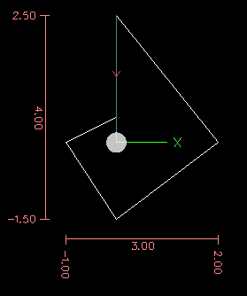
For example if you have the following program you might expect it to be a square pattern.
F100 G1 @.5 ^90
G91 @.5 ^90
@.5 ^90
@.5 ^90
@.5 ^90
G90 G0 X0 Y0 M2
You can see from the following figure that the output is not what you might expect. Because we added 0.5 to the distance each time the distance from the XY zero position increased with each line.
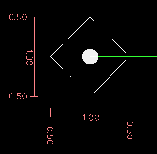
The following code will produce our square pattern.
F100 G1 @.5 ^90
G91 ^90
^90
^90
^90
G90 G0 X0 Y0 M2
As you can see by only adding to the angle by 90 degrees each time the end point distance is the same for each line.
It is an error if:
-
An incremental move is started at the origin
-
A mix of Polar and and X or Y words are used
15. Modal Groups
Modal commands are arranged in sets called modal groups, and only one member of a modal group may be in force at any given time. In general, a modal group contains commands for which it is logically impossible for two members to be in effect at the same time - like measure in inches vs. measure in millimeters. A machining center may be in many modes at the same time, with one mode from each modal group being in effect. The modal groups are shown in the following Table.
For several modal groups, when a machining center is ready to accept commands, one member of the group must be in effect. There are default settings for these modal groups. When the machining center is turned on or otherwise re-initialized, the default values are automatically in effect.
Group 1, the first group on the table, is a group of G codes for motion. One of these is always in effect. That one is called the current motion mode.
It is an error to put a G-code from group 1 and a G-code from group 0 on the same line if both of them use axis words. If an axis word-using G-code from group 1 is implicitly in effect on a line (by having been activated on an earlier line), and a group 0 G-code that uses axis words appears on the line, the activity of the group 1 G-code is suspended for that line. The axis word-using G-codes from group 0 are G10, G28, G30, and G92.
It is an error to include any unrelated words on a line with O- flow control.
16. Comments
Comments can be added to lines of G code to help clear up the intention of the programmer. Comments can be embedded in a line using parentheses () or for the remainder of a line using a semi-colon. The semi-colon is not treated as the start of a comment when enclosed in parentheses.
Comments may appear between words, but not between words and their corresponding parameter. So, S100(set speed)F200(feed) is OK while S(speed)100F(feed) is not.
G0 (Rapid to start) X1 Y1
G0 X1 Y1 (Rapid to start; but don't forget the coolant)
M2 ; End of program.
There are several active comments which look like comments but cause some action, like (debug,..) or (print,..). If there are several comments on a line, only the last comment will be interpreted according to these rules. Hence, a normal comment following an active comment will in effect disable the active comment. For example, (foo) (debug,#1) will print the value of parameter #1, however (debug,#1)(foo) will not.
A comment introduced by a semicolon is by definition the last comment on that line, and will always be interpreted for active comment syntax.
17. Messages
-
(MSG,) - displays message if MSG appears after the left parenthesis and before any other printing characters. Variants of MSG which include white space and lower case characters are allowed. The rest of the characters before the right parenthesis are considered to be a message. Messages should be displayed on the message display device of the user interface if provided.
(MSG, This is a message)
18. Probe Logging
-
(PROBEOPEN filename.txt) - will open filename.txt and store the 9-number coordinate consisting of XYZABCUVW of each successful straight probe in it.
-
(PROBECLOSE) - will close the open probelog file.
For more information on probing see the G38 Section.
19. Logging
-
(LOGOPEN,filename.txt) - opens the named log file. If the file already exists, it is truncated.
-
(LOGAPPEND,filename) - opens the named log file. If the file already exists, the data is appended.
-
(LOGCLOSE) - closes an open log file.
-
(LOG,) - everything past the , is written to the log file if it is open. Supports expansion of parameters as described below.
20. Debug Messages
-
(DEBUG,) - displays a message like (MSG,) with the addition of special handling for comment parameters as described below.
21. Print Messages
-
(PRINT,) - messages are output to stderr with special handling for comment parameters as described below.
22. Comment Parameters
In the DEBUG, PRINT and LOG comments, the values of parameters in the message are expanded.
For example: to print a named global variable to stderr (the default console window) add a line to your G code like…
(print,endmill dia = #<_endmill_dia>)
Inside the above types of comments, sequences like 123 are replaced by the value of the parameter 123. Sequences like <named parameter> are replaced by the value of the named parameter. Named parameters will have white space removed from them. So, <named parameter> will be converted to <namedparameter>.
23. File Requirements
A G code file must contain one or more lines of G code and be terminated with a Program End. Any G code past the program end is not evaluated.
If a program end code is not used a pair of percent signs % with the first percent sign on the first line of the file followed by one or more lines of G code and a second percent sign. Any code past the second percent sign is not evaluated.
|
Note
|
The file must be created with a text editor like Gedit and not a word processor like Open Office Word Processor. |
24. File Size
The interpreter and task are carefully written so that the only limit on part program size is disk capacity. The TkLinuxCNC and Axis interface both load the program text to display it to the user, though, so RAM becomes a limiting factor. In Axis, because the preview plot is drawn by default, the redraw time also becomes a practical limit on program size. The preview can be turned off in Axis to speed up loading large part programs. In Axis sections of the preview can be turned off using preview control comments.
25. G Code Order of Execution
The order of execution of items on a line is defined not by the position of each item on the line, but by the following list:
-
Comment (including message)
-
Set feed rate mode (G93, G94).
-
Set feed rate (F).
-
Set spindle speed (S).
-
Select tool (T).
-
HAL pin I/O (M62-M68).
-
Change tool (M6) and Set Tool Number (M61).
-
Spindle on or off (M3, M4, M5).
-
Save State (M70, M73), Restore State (M72), Invalidate State (M71).
-
Coolant on or off (M7, M8, M9).
-
Enable or disable overrides (M48, M49,M50,M51,M52,M53).
-
User-defined Commands (M100-M199).
-
Dwell (G4).
-
Set active plane (G17, G18, G19).
-
Set length units (G20, G21).
-
Cutter radius compensation on or off (G40, G41, G42)
-
Cutter length compensation on or off (G43, G49)
-
Coordinate system selection (G54, G55, G56, G57, G58, G59, G59.1, G59.2, G59.3).
-
Set path control mode (G61, G61.1, G64)
-
Set distance mode (G90, G91).
-
Set retract mode (G98, G99).
-
Go to reference location (G28, G30) or change coordinate system data (G10) or set axis offsets (G92, G92.1, G92.2, G94).
-
Perform motion (G0 to G3, G33, G73, G76, G80 to G89), as modified (possibly) by G53.
-
Stop (M0, M1, M2, M30, M60).
26. G Code Best Practices
26.1. Use an appropriate decimal precision
Use at least 3 digits after the decimal when milling in millimeters, and at least 4 digits after the decimal when milling in inches.
26.2. Use consistent white space
G-code is most legible when at least one space appears before words. While it is permitted to insert white space in the middle of numbers, there is no reason to do so.
26.3. Use Center-format arcs
Center-format arcs (which use I- J- K- instead of R- ) behave more consistently than R-format arcs, particularly for included angles near 180 or 360 degrees.
26.4. Put important modal settings at the top of the file
When correct execution of your program depends on modal settings, be sure to set them at the beginning of the part program. Modes can carry over from previous programs and from the MDI commands.
As a good preventative measure, put a line similar to the following at the top of all your programs:
G17 G20 G40 G49 G54 G80 G90 G94
(XY plane, inch mode, cancel diameter compensation, cancel length offset, coordinate system 1, cancel motion, non-incremental motion, feed/minute mode)
Perhaps the most critical modal setting is the distance units—If you do not include G20 or G21, then different machines will mill the program at different scales. Other settings, such as the return mode in canned cycles may also be important.
26.5. Don’t put too many things on one line
Ignore everything in Section [sec:Order-of-Execution], and instead write no line of code that is the slightest bit ambiguous.
26.6. Don’t set & use a parameter on the same line
Don’t use and set a parameter on the same line, even though the semantics are well defined. Updating a variable to a new value, such as #1=[#1+#2] is OK.
26.7. Don’t use line numbers
Line numbers offer no benefits. When line numbers are reported in error messages, the numbers refer to the line number in the file, not the N-word value.
27. Linear and Rotary Axis
Because the meaning of an F-word in feed-per-minute mode varies depending on which axes are commanded to move, and because the amount of material removed does not depend only on the feed rate, it may be easier to use G93 inverse time feed mode to achieve the desired material removal rate.
28. Common Error Messages
-
G code out of range - A G code greater than G99 was used, the scope of G codes in LinuxCNC is 0 - 99. Not every number between 0 and 99 is a valid G code.
-
Unknown g code used - A G code was used that is not part of the LinuxCNC G code language.
-
i,j,k word with no Gx to use it - i, j and k words must be used on the same line as the G code.
-
Cannot use axis values without a g code that uses them - Axis values can not be used on a line without either a modal G code in effect or a G code on the same line.
-
File ended with no percent sign or program end - Every G code file must end in a M2 or M30 or be wrapped with the percent sign %.