Table of Contents
List of figures
1 Mesa HostMot2
1.1 Introduction
HostMot2 is an FPGA configuration developed by Mesa Electronics for their line of "Anything I/O" motion control cards. The firmware is open source, portable and flexible. It can be configured (at compile-time) with zero or more instances (an object created at runtime) of each of several Modules: encoders (quadrature counters), PWM generators, and step/dir generators. The firmware can be configured (at run-time) to connect each of these instances to pins on the I/O headers. I/O pins not driven by a Module instance revert to general-purpose bi-directional digital I/O.
1.2 Firmware Binaries
Several pre-compiled HostMot2 firmware binaries are available for the different Anything I/O boards. (This list may be incomplete, check the EMC distribution and Mesa's web site for more up-to-date firmware lists.)
5i20, 5i23, 4i65, 4i68 (72 I/O pins): using hm2_pci module
- 12-channel servo
- 8-channel servo plus 4 step/dir generators
- 4-channel servo plus 8 step/dir generators
5i22 (96 I/O pins): using hm2_pci module
- 16-channel servo
- 8-channel servo plus 24 step/dir generators
7i43 (48 I/O pins): using hm2_7i43 module
- 8-channel servo (8 PWM generators & 8 encoders)
- 4-channel servo plus 4 step/dir generators
1.3 Installing Firmware
Depending on how you installed EMC2 you may have to open the Synaptic Package Manager from the System menu and install the package for your Mesa card. The quickest way to find them is to do a search for "emc" in the Synaptic Package Manager. Mark the firmware for installation then apply.
1.4 Loading HostMot2
The EMC support for the HostMot2 firmware is split into a generic driver called "hostmot2" and two low-level I/O drivers for the Anything I/O boards. The low-level I/O drivers are "hm2_7i43" and "hm2_pci" (for all the PCI- and PC-104/Plus-based AnyIO boards). The hostmot2 driver must be loaded first, using a HAL command like this:
loadrt hostmot2
See the hostmot2(9) man page for details.
The hostmot2 driver by itself does nothing, it needs access to actual boards running the HostMot2 firmware. The low-level I/O drivers provide this access. The low-level I/O drivers are loaded with commands like this:
loadrt hm2_pci config="firmware=hm2/5i20/SVST8_4.BIT num_encoders=3 num_pwmgens=3 num_stepgens=1"
The config parameters are described in the hostmot2 man page.
1.5 Watchdog
The HostMot2 firmware may include a watchdog Module; if it does, the hostmot2 driver will use it.
The watchdog must be petted by EMC2 periodically or it will bite.
When the watchdog bites, all the board's I/O pins are disconnected from their Module instances and become high-impedance inputs (pulled high), and all communication with the board stops. The state of the HostMot2 firwmare modules is not disturbed (except for the configuration of the IO Pins). Encoder instances keep counting quadrature pulses, and pwm- and step-generators keep generating signals (which are not relayed to the motors, because the IO Pins have become inputs).
Resetting the watchdog resumes communication and resets the I/O pins to the configuration chosen at load-time.
If the firmware includes a watchdog, the following HAL objects will be exported:
1.5.1 Pins:
- .has_bit:
- (bit i/o) True if the watchdog has bit, False if the watchdog has not bit. If the watchdog has bit and the has_bit bit is True, the user can reset it to False to resume operation.
1.5.2 Parameters:
- .timeout_ns:
- (u32 read/write) Watchdog timeout, in nanoseconds. This is initialized to 1,000,000,000 (1 second) at module load time. If more than this amount of time passes between calls to the pet_watchdog() function, the watchdog will bite.
1.5.3 Functions:
- .pet_watchdog():
- Calling this function resets the watchdog timer and postpones the watchdog biting until timeout_ns nanoseconds later. This function should be added to the servo thread.
1.6 HostMot2 Functions
- hm2_<BoardType>.<BoardNum>.read
- Read all inputs, update input HAL pins.
- hm2_<BoardType>.<BoardNum>.write
- Write all outputs.
- hm2_<BoardType>.<BoardNum>.pet-watchdog
- Pet the watchdog to keep it from biting us for a while.
- hm2_<BoardType>.<BoardNum>.read_gpio
- Read the GPIO input pins. (This function is not available on the 7i43 due to limitations of the EPP bus.)
- hm2_<BoardType>.<BoardNum>.write_gpio
- Write the GPIO control registers and output pins. (This function is not available on the 7i43 due to limitations of the EPP bus.)
1.7 Pinouts
The hostmot2 driver does not have a particular pinout. The pinout comes from the firmware that the hostmot2 driver sends to the AnyIO board. Each firmware has different pinout, and the pinout depends on how many of the available encoders, pwmgens, and stepgens are used. To get a pinout list for your configuration after loading EMC2 in the terminal window type:
dmesg > hm2.txt
The resulting text file will contain lots of information as well as the pinout for the HostMot2 and any error and warning messages.
To reduce the clutter by clearning the message buffer before loading EMC type the following in the terminal window:
sudo dmesg -c
Now when you run EMC and then do a "dmesg > hm2.txt" in the terminal only the info from the time you loaded EMC will be in your file along with your pinout. The file will be in the current directory of the terminal window. Each line will contain the card name, the card number, the I/O Pin number, the connector and pin, and the usage. From this printout you will know the physical connections to your card based on your configuration.
An example of a 5i20 configuration:
[HOSTMOT2]
DRIVER=hm2_pci
BOARD=5i20
CONFIG="firmware=hm2/5i20/SVST8_4.BIT num_encoders=1 num_pwmgens=1 num_stepgens=3"
The above configuration produced this printout .
[ 1141.053386] hm2/hm2_5i20.0: 72 I/O Pins used:
[ 1141.053394] hm2/hm2_5i20.0: IO Pin 000 (P2-01): IOPort
[ 1141.053397] hm2/hm2_5i20.0: IO Pin 001 (P2-03): IOPort
[ 1141.053401] hm2/hm2_5i20.0: IO Pin 002 (P2-05): Encoder #0, pin B (Input)
[ 1141.053405] hm2/hm2_5i20.0: IO Pin 003 (P2-07): Encoder #0, pin A (Input)
[ 1141.053408] hm2/hm2_5i20.0: IO Pin 004 (P2-09): IOPort
[ 1141.053411] hm2/hm2_5i20.0: IO Pin 005 (P2-11): Encoder #0, pin Index (Input)
[ 1141.053415] hm2/hm2_5i20.0: IO Pin 006 (P2-13): IOPort
[ 1141.053418] hm2/hm2_5i20.0: IO Pin 007 (P2-15): PWMGen #0, pin Out0 (PWM or Up) (Output)
[ 1141.053422] hm2/hm2_5i20.0: IO Pin 008 (P2-17): IOPort
[ 1141.053425] hm2/hm2_5i20.0: IO Pin 009 (P2-19): PWMGen #0, pin Out1 (Dir or Down) (Output)
[ 1141.053429] hm2/hm2_5i20.0: IO Pin 010 (P2-21): IOPort
[ 1141.053432] hm2/hm2_5i20.0: IO Pin 011 (P2-23): PWMGen #0, pin Not-Enable (Output)
<snip>...
[ 1141.053589] hm2/hm2_5i20.0: IO Pin 060 (P4-25): StepGen #2, pin Step (Output)
[ 1141.053593] hm2/hm2_5i20.0: IO Pin 061 (P4-27): StepGen #2, pin Direction (Output)
[ 1141.053597] hm2/hm2_5i20.0: IO Pin 062 (P4-29): StepGen #2, pin (unused) (Output)
[ 1141.053601] hm2/hm2_5i20.0: IO Pin 063 (P4-31): StepGen #2, pin (unused) (Output)
[ 1141.053605] hm2/hm2_5i20.0: IO Pin 064 (P4-33): StepGen #2, pin (unused) (Output)
[ 1141.053609] hm2/hm2_5i20.0: IO Pin 065 (P4-35): StepGen #2, pin (unused) (Output)
[ 1141.053613] hm2/hm2_5i20.0: IO Pin 066 (P4-37): IOPort
[ 1141.053616] hm2/hm2_5i20.0: IO Pin 067 (P4-39): IOPort
[ 1141.053619] hm2/hm2_5i20.0: IO Pin 068 (P4-41): IOPort
[ 1141.053621] hm2/hm2_5i20.0: IO Pin 069 (P4-43): IOPort
[ 1141.053624] hm2/hm2_5i20.0: IO Pin 070 (P4-45): IOPort
[ 1141.053627] hm2/hm2_5i20.0: IO Pin 071 (P4-47): IOPort
[ 1141.053811] hm2/hm2_5i20.0: registered
[ 1141.053815] hm2_5i20.0: initialized AnyIO board at 0000:02:02.0
Note that the IO Pin nnn will correspond to the pin number shown on the HAL Configuration screen for GPIO's. Some of the Stepgen, Encoder and PWMGen will also show up as GPIO's in the HAL Configuration screen.
1.8 PIN Files
The default pinout is described in a .PIN file.
If if you installed EMC2 the file is located in:
/usr/share/doc/emc2-firmware-mesa-<board>-hostmot2
In the source tree, the pin files are located in:
src/hal/drivers/mesa-hostmot2/firmware/<board>
1.9 Firmware Location
If your using Run In Place you will have to create a symbolic link to the bit files.
sudo ln -s <path to trunk>/src/hal/drivers/mesa-hostmot2/firmware /lib/firmware/hm2-trunk
And change the "firmware=hm2..." to "firmware=hm2-trunk..." in your ini file.
1.10 HAL Pins
The HAL pins for each configuration can be seen by opening up "Show HAL Configuration" from the Machine menu. All the HAL pins and parameters can be found there. The following figure is of the 5i20 configuration used above.
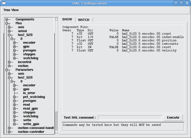 Figure: 5i20 HAL Pins
1.11 Configurations
5i20 & 5i23 Default Configurations
|
Firmware |
5i20 |
5i23 |
Encoder |
PWM |
StepGen |
GPIO |
|
SV12 |
X |
X |
12 |
12 |
0 |
0 |
|
SVST2_8 |
X |
|
2 |
2 |
8 |
12 |
|
SVST4_8 |
|
X |
4 |
4 |
8 |
0 |
|
SVST8_4 |
X |
X |
8 |
8 |
4 |
0 |
|
SVST8_4IM2 |
X |
X |
8 |
8 |
4 |
8 |
|
SVST8_8IM2 |
|
X |
8 |
8 |
8 |
0 |
4i65 & 4i68 Default Configurations
|
Firmware |
4i65 |
4i68 |
Encoder |
PWM |
StepGen |
GPIO |
|
SV12 |
X |
X |
12 |
12 |
0 |
0 |
|
SVST4_8 |
|
X |
4 |
4 |
8 |
0 |
|
SVST8_4 |
X |
X |
8 |
8 |
4 |
0 |
|
SVST8_4IM2 |
X |
X |
8 |
8 |
4 |
8 |
|
SVST8_8IM2 |
|
X |
8 |
8 |
8 |
0 |
7i43 Default Configurations
|
Firmware |
200K |
400K |
Encoder |
PWM |
StepGen |
GPIO |
|
SV8B |
|
X |
8 |
8 |
0 |
0 |
|
SV8S |
X |
|
8 |
8 |
0 |
0 |
|
SVST4_4B |
|
X |
4 |
4 |
4 |
0 |
|
SVST4_4S |
X |
|
4 |
4 |
4 |
0 |
|
SVST4_6B |
|
X |
4 |
4 |
6 |
0 |
|
SVST4_6S |
X |
|
4 |
4 |
6 |
0 |
|
SVST4_12B |
|
X |
4 |
4 |
12 |
0 |
The 7i43 comes in 200K and 400K gate versions.
Even though several cards may have the same .BIT file you can not use a .BIT file that is not for that card. Different cards have different clock frequencies so make sure you load the proper .BIT file for your card. Custom hm2 firmwares can be created for special applications and you may see some custom hm2 firmwares in the directories with the default ones.
When you load the board-driver (hm2_pci or hm2_7i43), you can tell it to disable instances of the three primary modules (pwmgen, stepgen, and encoder) by setting the count lower. Any I/O pins belonging to disabled module instances become gpios.
1.12 GPIO
General Purpose I/O pins on the board which are not used by a module instance are exported to HAL as "full" GPIO pins. Full GPIO pins can be configured at run-time to be inputs, outputs, or open drains, and have a HAL interface that exposes this flexibility. IO pins that are owned by an active module instance are constrained by the requirements of the owning module, and have a restricted HAL interface.
GPIOs have names like "hm2_<BoardType>.<BoardNum>.gpio.<IONum>." IONum. is a three-digit number. The mapping from IONum to connector and pin-on-that-connector is written to the syslog when the driver loads, and it's documented in Mesa's manual for the Anything I/O boards.
The hm2 GPIO representation is modeled after the Digital Inputs and Digital Outputs described in the Canonical Device Interface (part of the HAL General Reference document).
GPIO pins default to input.
1.12.1 Pins
- .in
- (Bit, Out) Normal state of the hardware input pin. Both full GPIO pins and IO pins used as inputs by active module instances have this pin.
- .in_not
- (Bit, Out) Inverted state of the hardware input pin. Both full GPIO pins and IO pins used as inputs by active module instances have this pin.
- .out
- (Bit, In) Value to be written (possibly inverted) to the hardware output pin. Only full GPIO pins have this pin.
1.12.2 Parameters
- .invert_output
- (Bit, RW) This parameter only has an effect if the "is_output" parameter is true. If this parameter is true, the output value of the GPIO will be the inverse of the value on the "out" HAL pin. Only full GPIO pins and IO pins used as outputs by active module instances have this parameter.
- .is_opendrain
- (Bit, RW) This parameter only has an effect if the "is_output" parameter is true. If this parameter is false, the GPIO behaves as a normal output pin: the IO pin on the connector is driven to the value specified by the "out" HAL pin (possibly inverted), and the value of the "in" and "in_not" HAL pins is undefined. If this parameter is true, the GPIO behaves as an open-drain pin. Writing 0 to the "out" HAL pin drives the IO pin low, writing 1 to the "out" HAL pin puts the IO pin in a high-impedance state. In this high-impedance state the IO pin floats (weakly pulled high), and other devices can drive the value; the resulting value on the IO pin is available on the "in" and "in_not" pins. Only full GPIO pins and IO pins used as outputs by active module instances have this parameter.
- .is_output
- (Bit, RW) If set to 0, the GPIO is an input. The IO pin is put in a high-impedance state (weakly pulled high), to be driven by other devices. The logic value on the IO pin is available in the "in" and "in_not" HAL pins. Writes to the "out" HAL pin have no effect. If this parameter is set to 1, the GPIO is an output; its behavior then depends on the "is_opendrain" parameter. Only full GPIO pins have this parameter.
1.13 StepGen
Stepgens have names like "hm2_<BoardType>.<BoardNum>.stepgen.<Instance>.". "Instance" is a two-digit number that corresponds to the HostMot2 stepgen instance number. There are "num_stepgens" instances, starting with 00.
Each stepgen allocates 2-6 IO pins (selected at firmware compile time), but currently only uses two: Step and Direction outputs.
The stepgen representation is modeled on the stepgen software component. Stepgen default is active high step output (high during step time low during step space).
Each stepgen instance has the following pins and parameters:
1.13.1 Pins
- .counts
- (s32, Out) Feedback position in counts (number of steps).
- .enable
- (Bit, In) Enables output steps. When false, no steps are generated.
- .position-cmd
- (Float, In) Target of stepper motion, in arbitrary position units.
- .position-fb
- (Float, Out) Feedback position in arbitrary position units (counts / position_scale).
- .velocity-fb
- (Float, Out) Feedback velocity in arbitrary position units per second.
1.13.2 Parameters
- .dirhold
- (u32, RW) Minimum duration of stable Direction signal after a step ends, in nanoseconds.
- .dirsetup
- (u32, RW) Minimum duration of stable Direction signal before a step begins, in nanoseconds.
- .maxaccel
- (Float, RW) Maximum acceleration, in position units per second per second. If set to 0, the driver will not limit its acceleration.
- .maxvel
- (Float, RW) Maximum speed, in position units per second. If set to 0, the driver will choose the maximum velocity based on the values of steplen and stepspace (at the time that maxvel was set to 0).
- .position-scale
- (Float, RW) Converts from counts to position units. position = counts / position_scale
- .step_type
- (u32, RW) Output format, like the step_type modparam to the software stegen(9) component. 0 = Step/Dir, 1 = Up/Down, 2 = Quadrature. In Quadrature mode (step_type=2), the stepgen outputs one complete Gray cycle (00 -> 01 -> 11 -> 10 -> 00) for each "step" it takes.
- .steplen
- (u32, RW) Duration of the step signal, in nanoseconds.
- .stepspace
- (u32, RW) Minimum interval between step signals, in nanoseconds.
1.13.3 Step and Direction Parameters
The Step and Direction pins of each StepGen have two additional parameters. To find which I/O pin belongs to which step and direction output run dmesg as described above.
- .invert_output
- (Bit, RW) This parameter only has an effect if the "is_output" parameter is true. If this parameter is true, the output value of the GPIO will be the inverse of the value on the "out" HAL pin.
- .is_opendrain
- (Bit, RW) If this parameter is false, the GPIO behaves as a normal output pin: the IO pin on the connector is driven to the value specified by the "out" HAL pin (possibly inverted). If this parameter is true, the GPIO behaves as an open-drain pin. Writing 0 to the "out" HAL pin drives the IO pin low, writing 1 to the "out" HAL pin puts the IO pin in a high-impedance state. In this high-impedance state the IO pin floats (weakly pulled high), and other devices can drive the value; the resulting value on the IO pin is available on the "in" and "in_not" pins. Only full GPIO pins and IO pins used as outputs by active module instances have this parameter.
1.14 PWMGen
PWMgens have names like "hm2_<BoardType>.<BoardNum>.pwmgen.<Instance>.". "Instance" is a two-digit number that corresponds to the HostMot2 pwmgen instance number. There are "num_pwmgens" instances, starting with 00.
In HM2, each pwmgen uses three output IO pins: Not-Enable, Out0, and Out1.
The function of the Out0 and Out1 IO pins varies with output-type parameter (see below).
The hm2 pwmgen representation is similar to the software pwmgen component. Each pwmgen instance has the following pins and parameters:
1.14.1 Pins
- .enable
- (Bit, In) If true, the pwmgen will set its Not-Enable pin false and output its pulses. If "enable" is false, pwmgen will set its Not-Enable pin true and not output any signals.
- .value
- (Float, In) The current pwmgen command value, in arbitrary units.
1.14.2 Parameters
- .output-type
- (s32, RW) This emulates the output_type load-time argument to the software pwmgen component. This parameter may be changed at runtime, but most of the time you probably want to set it at startup and then leave it alone. Accepted values are 1 (PWM on Out0 and Direction on Out1), 2 (Up on Out0 and Down on Out1), 3 (PDM mode, PDM on Out0 and Dir on Out1), and 4 (Direction on Out0 and PWM on Out1, "for locked antiphase").
- .scale
- (Float, RW) Scaling factor to convert "value" from arbitrary units to duty cycle: dc = value / scale. Duty cycle has an effective range of -1.0 to +1.0 inclusive, anything outside that range gets clipped.
- .pdm_frequency
- (u32, RW) This specifies the PDM frequency, in Hz, of all the pwmgen instances running in PDM mode (mode 3). This is the "pulse slot frequency"; the frequency at which the pdm generator in the AnyIO board chooses whether to emit a pulse or a space. Each pulse (and space) in the PDM pulse train has a duration of 1/pdm_frequency seconds. For example, setting the pdm_frequency to 2e6 (2 MHz) and the duty cycle to 50% results in a 1 MHz square wave, identical to a 1 MHz PWM signal with 50% duty cycle. The effective range of this parameter is from about 1525 Hz up to just under 100 MHz. Note that the max frequency is determined by the ClockHigh frequency of the Anything IO board; the 5i20 and 7i43 both have a 100 MHz clock, resulting in a 100 Mhz max PDM frequency. Other boards may have different clocks, resulting in different max PDM frequencies. If the user attempts to set the frequency too high, it will be clipped to the max supported frequency of the board.
- .pwm_frequency
- (u32, RW) This specifies the PWM frequency, in Hz, of all the pwmgen instances running in the PWM modes (modes 1 and 2). This is the frequency of the variable-duty-cycle wave. Its effective range is from 1 Hz up to 193 KHz. Note that the max frequency is determined by the ClockHigh frequency of the Anything IO board; the 5i20 and 7i43 both have a 100 MHz clock, resulting in a 193 KHz max PWM frequency. Other boards may have different clocks, resulting in different max PWM frequencies. If the user attempts to set the frequency too high, it will be clipped to the max supported frequency of the board. Frequencies below about 5 Hz are not terribly accurate, but above 5 Hz they're pretty close.
1.14.3 Output Parameters
The output pins of each PWMGen have two additional parameters. To find which I/O pin belongs to which output run dmesg as described above.
- .invert_output
- (Bit, RW) This parameter only has an effect if the "is_output" parameter is true. If this parameter is true, the output value of the GPIO will be the inverse of the value on the "out" HAL pin.
- .is_opendrain
- (Bit, RW) If this parameter is false, the GPIO behaves as a normal output pin: the IO pin on the connector is driven to the value specified by the "out" HAL pin (possibly inverted). If this parameter is true, the GPIO behaves as an open-drain pin. Writing 0 to the "out" HAL pin drives the IO pin low, writing 1 to the "out" HAL pin puts the IO pin in a high-impedance state. In this high-impedance state the IO pin floats (weakly pulled high), and other devices can drive the value; the resulting value on the IO pin is available on the "in" and "in_not" pins. Only full GPIO pins and IO pins used as outputs by active module instances have this parameter.
1.15 Encoder
Encoders have names like "hm2_<BoardType>.<BoardNum>.encoder.<Instance>.". "Instance" is a two-digit number that corresponds to the HostMot2 encoder instance number. There are "num_encoders" instances, starting with 00.
Each encoder uses three or four input IO pins, depending on how the firmware was compiled. Three-pin encoders use A, B, and Index (sometimes also known as Z). Four-pin encoders use A, B, Index, and Index-mask.
The hm2 encoder representation is similar to the one described by the Canonical Device Interface (in the HAL General Reference document), and to the software encoder component. Each encoder instance has the following pins and parameters:
1.15.1 Pins
- .count
- (s32, Out) Number of encoder counts since the previous reset.
- .index-enable
- (Bit, I/O) When this pin is set to True, the count (and therefore also position) are reset to zero on the next Index (Phase-Z) pulse. At the same time, index-enable is reset to zero to indicate that the pulse has occurred.
- .position
- (Float, Out) Encoder position in position units (count / scale).
- .rawcounts
- (s32, Out) Total number of encoder counts since the start, not adjusted for index or reset.
- .reset
- (Bit, In) When this pin is TRUE, the count and position pins are set to 0. (The value of the velocity pin is not affected by this.) The driver does not reset this pin to FALSE after resetting the count to 0, that is the user's job.
- .velocity
- (Float, Out) Estimated encoder velocity in position units per second.
1.15.2 Parameters
- .counter-mode
- (Bit, RW) Set to False (the default) for Quadrature. Set to True for Up/Down or for single input on Phase A. Can be used for a frequency to velocity converter with a single input on Phase A when set to true.
- .filter
- (Bit, RW) If set to True (the default), the quadrature counter needs 15 clocks to register a change on any of the three input lines (any pulse shorter than this is rejected as noise). If set to False, the quadrature counter needs only 3 clocks to register a change. The encoder sample clock runs at 33 MHz on the PCI AnyIO cards and 50 MHz on the 7i43.
- .index-invert
- (Bit, RW) If set to True, the rising edge of the Index input pin triggers the Index event (if index-enable is True). If set to False, the falling edge triggers.
- .index-mask
- (Bit, RW) If set to True, the Index input pin only has an effect if the Index-Mask input pin is True (or False, depending on the index-mask-invert pin below).
- .index-mask-invert
- (Bit, RW) If set to True, Index-Mask must be False for Index to have an effect. If set to False, the Index-Mask pin must be True.
- .scale
- (Float, RW) Converts from "count" units to "position" units. A quadrature encoder will normally have 4 counts per pulse so a 100 PPR encoder would have 400 counts per revolution. In .counter-mode a 100 PPR encoder would have 100 counts per revelution as it only uses the rising edge of A and direction is B.
- .vel-timeout
- (Float, RW) When the encoder is moving slower than one pulse for each time that the driver reads the count from the FPGA (in the hm2_read() function), the velocity is harder to estimate. The driver can wait several iterations for the next pulse to arrive, all the while reporting the upper bound of the encoder velocity, which can be accurately guessed. This parameter specifies how long to wait for the next pulse, before reporting the encoder stopped. This parameter is in seconds.
1.16 Examples
Several example configurations are included with EMC for both stepper and servo applications. The configurations are located in the hm2-servo and hm2-stepper sections of the EMC2 Configuration Selector window. You will need the same board installed for the configuration you pick to load. The examples are a good place to start and will save you time. Just pick the proper example from the EMC2 Configuration Selector and save a copy to your computer so you can edit it. To see the exact pins and parameters that your configuration gave you open the Show HAL Configuration window from the Machine menu or do dmesg as outlined above.
Index