1. 简介
In this chapter, we will try to demystify coordinate systems. It is a very important concept to understand the operation of a CNC machine, its configuration and its use.
We will also show that it is very interesting to use a reference point on the blank or the part and to make the program work from this point, without having to take into account where the part is placed on the table.
This chapter introduces you to offsets as they are used by the LinuxCNC. These include:
-
Machine Coordinates (G53)
-
Nine Coordinate System Offsets (G54-G59.3)
-
Global Offsets (G92) and Local Offsets (G52)
2. Machine Coordinate System
When LinuxCNC is started the positions of each axis is the machine origin. Once an axis is homed, the machine origin for that axis is set to the homed position. The machine origin is the machine coordinate system on which all other coordinate systems are based. The G53 G-code can be used to move in the machine coordinate system.
2.1. Machine coordinates moves: G53
Regardless of any offset that may be active, a G53 in a line of code tells the interpreter to move to the actual axes positions (absolute positions) specified. For example:
will move from the current position to the position where the machine coordinates of the three axes will be at zero. You can use this command if you have a fixed position for the tool change or if your machine has an automatic tool changer. You can also use this command to clear the work area and access the workpiece in the vise.
G53 is a non modal command. It must be used in every block where a move in machine coordinate system is desired.
3. Coordinate Systems
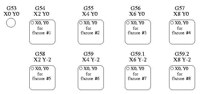
-
G54 - use coordinate system 1
-
G55 - use coordinate system 2
-
G56 - use coordinate system 3
-
G57 - use coordinate system 4
-
G58 - use coordinate system 5
-
G59 - use coordinate system 6
-
G59.1 - use coordinate system 7
-
G59.2 - use coordinate system 8
-
G59.3 - use coordinate system 9
Coordinate system offsets are used to shift the coordinate system from the machine coordinate system. This allows the G-code to be programmed for the part without regard to the part location on the machine. Using coordinate system offsets would allow you to machine parts in multiple locations with the same G-code.
The values for offsets are stored in the VAR file that is requested by the INI file during the startup of an LinuxCNC. In the example below, which uses G55, the position of each axis for G55 origin is stored in a numbered variable.
In the VAR file scheme, the first variable number stores the X offset, the second the Y offset and so on for all nine axes. There are numbered sets like this for each of the coordinate system offsets.
Each of the graphical interfaces has a way to set values for these offsets. You can also set these values by editing the VAR file itself and then restart LinuxCNC so that the LinuxCNC reads the new values however this is not the recommended way. Using G10, G52, G92, G28.1, etc are better ways to set the variables. For our example, we will directly edit the file so that G55 will take the following values:
| Axis | Variable | Value |
|---|---|---|
X |
5241 |
2.000000 |
Y |
5242 |
1.000000 |
Z |
5243 |
-2.000000 |
A |
5244 |
0.000000 |
B |
5245 |
0.000000 |
C |
5246 |
0.000000 |
U |
5247 |
0.000000 |
V |
5248 |
0.000000 |
W |
5249 |
0.000000 |
You should read this as moving the zero positions of G55 to X = 2 units, Y= 1 unit, and Z = -2 units away from the absolute zero position.
Once there are values assigned, a call to G55 in a program block would shift the zero reference by the values stored. The following line would then move each axis to the new zero position. Unlike G53, G54 through G59.3 are modal commands. They will act on all blocks of code after one of them has been set. The program that might be run using fixture offsets would require only a single coordinate reference for each of the locations and all of the work to be done there. The following code is offered as an example of making a square using the G55 offsets that we set above.
In this example the G54 near the end leaves the G54 coordinate system with all zero offsets so that there is a modal code for the absolute machine based axis positions. This program assumes that we have done that and use the ending command as a command to machine zero. It would have been possible to use G53 and arrive at the same place but that command would not have been modal and any commands issued after it would have returned to using the G55 offsets because that coordinate system would still be in effect.
G10 L2 P1 X0 Y0 Z0 (ensure that G54 is set to machine zero) G0 X-0.1 Y0 Z0 G1 F1 Z-0.25 G3 X-0.1 Y0 I0.1 J0 G0 Z0 M2
We can issue a set of commands to create offsets for the four other circles like this.

[source, {ngc}]
G10 L2 P2 X0.5 (offsets G55 X value by 0.5 inch) G10 L2 P3 X-0.5 (offsets G56 X value by -0.5 inch) G10 L2 P4 Y0.5 (offsets G57 Y value by 0.5 inch) G10 L2 P5 Y-0.5 (offsets G58 Y value by -0.5 inch)
We put these together in the following program:

[source, {ngc}]
(a program for milling five small circles in a diamond shape)
G10 L2 P1 X0 Y0 Z0 (ensure that G54 is machine zero) G10 L2 P2 X0.5 (offsets G55 X value by 0.5 inch) G10 L2 P3 X-0.5 (offsets G56 X value by -0.5 inch) G10 L2 P4 Y0.5 (offsets G57 Y value by 0.5 inch) G10 L2 P5 Y-0.5 (offsets G58 Y value by -0.5 inch)
G54 G0 X-0.1 Y0 Z0 (center circle) G1 F1 Z-0.25 G3 X-0.1 Y0 I0.1 J0 G0 Z0
G55 G0 X-0.1 Y0 Z0 (first offset circle) G1 F1 Z-0.25 G3 X-0.1 Y0 I0.1 J0 G0 Z0
G56 G0 X-0.1 Y0 Z0 (second offset circle) G1 F1 Z-0.25 G3 X-0.1 Y0 I0.1 J0 G0 Z0
G57 G0 X-0.1 Y0 Z0 (third offset circle) G1 F1 Z-0.25 G3 X-0.1 Y0 I0.1 J0 G0 Z0
G58 G0 X-0.1 Y0 Z0 (fourth offset circle) G1 F1 Z-0.25 G3 X-0.1 Y0 I0.1 J0 G54 G0 X0 Y0 Z0
4. M2
Now comes the time when we might apply a set of G92 offsets to this program. You’ll see that it is running in each case at Z0. If the mill were at the zero position, a G92 Z1.0000 issued at the head of the program would shift everything an inch. You might also shift the whole pattern around in the XY plane by adding some X and Y offsets with G92. If you do this you should add a G92.1 command just before the M2 that ends the program. If you do not, other programs that you might run after this one will also use that G92 offset. Furthermore it would save the G92 values when you shut down the LinuxCNC and they will be recalled when you start up again.
4.1. Sample Program Using G52 Offsets
(To be written)