1. Stepper Voltage
What Voltage should the power supply be?
To calculate the voltage needed empirically take a 24 VDC power supply or any power supply that you have on hand that is above the minimum for the drive and hook it to the heaviest loaded axis.
Run that axis and increase the speed until you find the fastest speed that it will run without missing steps with the test voltage.
Using the following formula you can determine your voltage needed. Speed you want ÷ (Speed you got * 0.9) * Test voltage used = Voltage needed Example (300IPM ÷ (150IPM * 0.9) * 24VDC = 53.3VDC Just make sure that the voltage is within the range of your stepper driver.
What Voltage is my Stepper?
Some steppers just have the resistance and current on the tag. Using Ohm’s Law R x I = E (Resistance x Current = Voltage) Example 1.1 Ohms x 2.8 Amps = 3.08 Volts
Compute Maximum Voltage vs Inductance
To compute the maximum voltage that you should use depending on the inductance of the motor use this formula. Maximum Voltage = 1000 * SQRT(inductance)
Example a motor that is rated at 1.5mH inductance per phase. 1000 * SQRT(0.0015) = 38.73 Volts MAXIMUM. Example a motor that is rated at 6mH per phase 1000 * SQRT(0.006) = 77 Volts MAXIMUM. Example a motor that is rated 2.5mH 1000 * SQRT(0.0025) = 50VDC MAXIMUM.
|
Note
|
Not all motors are created equal. If you use this formula and your motor seems to be excessively hot, turn down the voltage until the temperature is acceptable. Stepper motors are designed to run hot, but there’s no need to stink up the place with fried insulation. Many motors are rated to withstand an 80 C temperature rise. For my own purposes, I limit the temperature rise to 60 C. |
Compute Value and Wattage of Current-Limiting Resistors
Note: For L/R systems only.
This is a basic application of Ohms Law for a series circuit. Your resistor must drop the difference in voltage between the voltage at which your stepper is rated and your supply voltage:
Resistor voltage drop = Supply voltage - stepper rated voltage
Applying Ohms Law, divide by the rated current to get the resistance:
Resistor value = Resistor voltage drop / stepper current
Finally, and very importantly, you need to know how much wattage you will be dissipating as heat, which your resistors must be rated to handle:
Resistor wattage rating = Resistor voltage drop * stepper current
For example: Steppers rated at 2.5V @ 5A, with a 26V power supply
Resistor voltage drop = 26V - 2.5V = 23.5V Resistor value = 23.5V / 5A = 4.7 Ohms Resistor wattage rating = 23.5V * 5A = 117.5 Watts
2. Stepper Motor Speed
Among the things that slow down a stepper motor are: Coil Inductance, drive voltage, resonance, decay mode, microstepping, and the clocking limitations introduced by using the main thread to drive through the parallel port. Here at the beginning I would like to discuss what the implications are for using stepper motors instead of very high speed (and high cost) servo systems.
3. Stepper Torque
What will be consuming the torque of the system? If allthread is used for the leadscrew, it will consume a lot of the torque applied. ACME threaded leadscrews will consume less, but a ballscrew will consume nearly none of the available torque. Acceleration and deceleration will use some of the torque until the axis reaches the speed that is set. For high speed moves like to and from the tool changer, these are the only drains on the torque. When you start cutting, the hardness of the material along with the cubic inches per minute that is being removed and the sharpness of the tool affect the torque requirements.
Let’s start with a system with a standard 200 step per revolution stepper motor running in full step mode. Let’s choose a motor that will need 100uS per step if it is to maintain full torque. If it drives a 20 thread per inch all thread leadscrew, it will require 4000 steps per inch, giving ¼ of a thousandth of an inch resolution. This requires .4 seconds per inch, which is 150 Inches Per Minute (IPM). If this motor is sized to provide a lot of torque for cutting, then when doing high speed moves, the motor can be driven faster, into the region where the torque decreases. This system in practice might be suitable for 300 IPM high speed moves without losing steps. For most hobby uses this is quite fast.
The most torque will be needed when you are cutting a large amount of metal with a large bit, as in shell milling. Wood milling requires less force per cubic inch per second than most metals, but the torque is still needed most when making a heavy cut. When making a heavy cut, the spindle power, and the strength of the tool will probably limit the maximum speed of the cut. I’ve rarely seen a machine tool cutting at more than 25 IPM, though some videos on YouTube show a router cutting MDF at a pretty good clip. For most stepper motor systems the speed used for cutting will be slow enough that the stepper motor will be putting out it’s full torque during cutting, even if it’s not fast at full speed.
Tormach machine tool maker has a PDF on the design of their PCNC1100, and they describe the design decisions made for that machine. I find it worth quoting them about speed and power.
“A 1.5 hp CNC mill with 65 IPM rapids and no tool changer is ludicrous in a production environment, where minutes per piece are crucial. However, in prototype development, where run time is a tiny fraction of setup time, those extra minutes are simply not relevant.“
I believe 65 IPM rapids are easily attainable with careful selection of stepper motor components, so I believe steppers are useful for most of us.
4. Coil Inductance
Probably the most limiting factor in the ultimate speed of a stepper motor system is the inductance designed into the stepper motor. If you wind a 2 milliHenry coil using 18 guage wire you’ll need about 3x times more turns if you use an air core than if you use an iron core. In a stepper motor the structure of the motor requires an iron core to get 200 steps per revolution. with air core coils you might get 20 steps per revolution.
Because of the structure of the stepper motor, the lowest inductance I have seen quoted for a stepper motor is around 1 mH (milliHenry) per coil, while many rate 12 mH or higher. In the graphs below you will see plots of charge time for a 2mH (red), a 4mH (blue), and an 8mH (green) coil charged from a 90Volt supply.
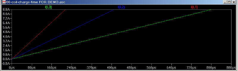
By 80 uS (microseconds) the 2 mH coil has achieved 3.2 Amps. At that same time, the 8 mH coil has only achieved about 0.9 Amps. If the stepper motor is rated at a certain torque at 3 Amps, but it only gets to 0.9 Amps it would seem like you have a little less than 1/3 of the rated torque at 80 uS per step, but it’s even less than that, since it only starts exerting that 1/3 torque at the 80 uS mark. At 40 uS it may only be delivering 1/6 of the full rated torque.
5. Drive Voltage
Below is a graph of a 2 mH coil charged from a 12V supply (red), a 24V supply (blue) and a 48V supply (green).
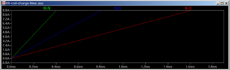
If you are using the same 3A motor, it takes about 150uS for a 48V supply to bring this motor up to 3A. It takes the 24V supply about 300uS to achieve the same current level. The 12V supply takes about 4 times as long as the 48V supply. Most switch mode IC stepper motor controllers limit the supply voltage you may use. The Allegro A3977 which is a great bipolar stepper motor controller chip has limits at 2.5A and 35V. The unipolar Sanken SLA7062M limits you to 3A and a 46V supply. Usually the insulation in the stepper motor can handle more voltage than 46, so with a discreet transistor solution you may be able to use 80V to 90V for your supply. 90V should allow your stepper motor to charge in about ½ the time that it would take a 45V supply. In case a suitable discreet option is available to you, <b>there are plenty of 80 to 90V supplies available for free. An old 100Watt stereo amplifier will have bipolar supplies over +-40V giving a differential of over 80V</b>. You can use one half of this supply for the SLA7062M, and a lower power amplifier could have a power supply suitable for the Allegro A3977. In the users manual for the Geckodrive G540 which is a complete system with four stepper motor controllers and inputs for limit switches, etc.; when discussing the selection of stepper motors says:
“Never use a power supply voltage greater than 32 times the square-root of the motor inductance expressed in milli-Henries (mH)” That would limit the power supply to 45 volts for a 2mH stepper motor used with this controller, which is not a terrible limitation.
While I’m talking about the power supply, it’s worth noting that a stepper motor controller that uses a linear current regulator (IE the LiniStepper) would put the full 6A load on the power supply continuously. That would tax the power capability of most audio amplifier power supplies. A switching regulator only draws from the power supply for brief amounts of time, so a stepper motor that draws 3A at 2 volts per coil, would draw 3A x 2V = 6 Watts per coil or 12 Watts. At 48 volts 12 Watts would only require .25A. Three such motors would require 75A. This is well within the limits of a 100W per channel audio amplifier power supply. If you over rate your power supply by a factor of 2, you should be safe, except that the capacitors of an audio amplifier are not designed to take the peak currents that switching regulators draw, so having an additional capacitor rated for switching supplies would be necessary. A commercial switching stepper motor controller may have the high frequency capacitor built in.
6. Resonance
Resonance is a little gremlin that tries to hide in your machine, and eat your torque. Usually it can only eat your torque at a certain speed. The trouble is, if that speed is below your system’s top speed, you can never get past it to your top speed. If you put a weight on a spring, and pull the weight down then let go, the weight will oscillate up and down at a particular speed. If you double the stiffness of the spring, it will oscillate twice as fast. If you cut the weight in half, it will oscillate twice as fast. Anything in your machine that flexes is one of those springs. If it’s stiff enough, the oscillation (resonance) will be fast enough that you will never excite it. You will never lose torque to that resonance. If you can’t make that part stiff enough, there are other techniques to reduce the effects of the resonance.
# Rubber Couplings. # Friction. # Loosely coupled weights.
Rubber couplings are often used to reduce the resonance. A short piece of rubber hose coupling your stepper motor to your leadscrew can help a lot.
The friction in an allthread leadscrew can damp out a resonance, but it also uses up some of your torque all the time.
7. Decay Mode
To understand decay mode, and it’s effect on a stepper motor, I found the data sheet for the Allegro A3955 (a 423kB PDF) very informative. Allegro has a patent on a mixed decay mode that gives us the best of both worlds. If the decay is slow, then when the current in the coil needs to be reduced, it doesn’t reduce the current quickly enough to match the commanded current level, if the decay mode is too fast, the motor performs quickly, but it can get noisy, and some power gets wasted in eddy currents that normally wouldn’t have to.
8. Microstepping
The benefits of microstepping include:
# increasing the resolution of a given motor or system # reducing noise in a stepper motor system and # it may reduce or eliminate a resonance in the system.
Microstepping shouldn’t affect the step motor speed much because of coil charging since while you are increasing the steps per revolution, each step now has to change the coil current a smaller amount. With a fast controller microstepping should only be a small percentage slower than full stepping. Where microstepping can slow the system down is by bumping into the limitations of the parallel port earlier, at lower RPM.
Microstepping does have a limitation though. Let’s consider a stepper motor which draws 707mA through each coil when full stepping, and therefore providing full torque for each step. If it is microstepped at 4X microstepping, the current levels for each coil will step through a sequence of 0.0 mA, 382 mA, 707 mA, 924 mA, and finally 1000 mA. 4X microstepping gives torque as if you were running a motor designed for 707 mA at 382 mA full step. That is about 0.54 times the full torque. Jeramé Chamberlain of Nippon Pulse America put out 2 PDFs on servicing stepper motor systems, and here is a portion of his list of the torque for different microstepping modes:
| MICROSTEPS | % FULLSTEP TORQUE |
|---|---|
1 |
100% |
2 |
70.17% |
4 |
38.27% |
8 |
19.51% |
16 |
9.80% |
Some lists have full stepping and half stepping at full rated torque, assuming that when only one coil is driven, you can increase the current by 1.414 and still pump the same power into the motor, but since that power would be localized in just one coil, it’s best not to use the full 100% torque at half stepping, unless you reduce current in the motor, and the extra current doesn’t create a field large enough to degauss the permanent magnets.
When you choose microstepping, though you get extra resolution, it comes at the cost of torque AT that resolution. If there is too much static friction for this much torque, the motor may pile a few microsteps together before it provides enough torque to break the static friction. Then, the machine may move 2 or 3 microsteps before stopping again to wait. If the machine has low friction, but is cutting a heavy cut that requires lots of torque, the stepper motor’s position may get a few microsteps behind the commanded position.
When making square cuts, like cutting the outside of a square housing, though the machine may get behind the commanded position in the middle of the cut, the machine will decelerate to 0 before making a change of direction at the corner. At this really low speed, the low torque may be able to catch up to the commanded position before changing direction. Even a poorly tuned servo system can get behind while doing a heavy cut, yet it may not be noticed on rectangular shapes since it can catch up in the corners. Where this may cause problems is when cutting out a continual circular pocket or post. In this case being behind the commanded position can make the inside diameter smaller than commanded, or the outside diameter larger than commanded. If you are doing art, the smoothness of the cut may be more desirable than the absolute accuracy. In this case microstepping may be the right choice.
The crux? Be aware of the liabilities as well as the benefits of microstepping before you choose to use it. A cogged belt reduction may be more useful than microstepping in some instances.
9. Force Calculations
This is a spreadsheet to calculate force for steppers or servos. Mechanical Spreadsheet
10. Parallel Port Limitations
If you are running a stepper system from a parallel port, the latency test is the first thing you need to run. Be aware that on board video can cause an otherwise fine motherboard to have terrible latency, but a cheap external video card usually fixes that.
Now let’s suppose you have a great latency reading of 6000 nS, or 6 uS. This should allow you to run a main thread at 10uS. Lets further assume your stepper motor controller accepts quadrature as it’s input, which allows one step per thread, or one step per 10 uS. We are ignoring the signal timing requirements of the stepper controller for now. At 10uS per step, if you have resolution of .001 inch per step, theoretically you can step an inch in 10 mS. That’s 100 inches per second or 6000 inches per minute. WOW! That parallel port shouldn’t be any limit at all! Well, not so fast. .001” resolution is not that great, let’s cut it down by a factor of 4. 250 micro inches per step seems usable. Now we’re down to 1500 IPM. Still seems very fast! But we’re still not done running into the wall physics puts in front of us. Let’s consider the change in speed we need as we approach this 1500 IPM which occurs at 10 uS per step. Consider this table:
MICROSECONDS PER STEP |
10 |
20 |
30 |
40 |
50 |
60 |
70 |
80 |
100 |
200 |
% CHANGE IN SPEED |
100 |
50 |
33.3 |
25 |
20 |
16.7 |
14.3 |
12.5 |
10 |
5 |
It is unrealistic to expect a stepper motor to double it’s speed from 20 uS per step to 10 uS per step. 50%, 33.3%, 25%, and 20% changes in speed seem to be unrealistic too. At what percent change can your system make the change? I can’t answer that. Experimentation is probably the only way to find that answer. This is the reason why an FPGA board often used for servo systems, may be useful for a stepper system. When the resolution at 100 MHz is 10 nS, at 10 uS per step the % change is 0.1%, and realistic to expect a stepper to keep up with.
If our stepper motor can handle a 5% change in speed at high speed, our 6000 nS latency is only good for 75 IPM high speed. At 200 uS per step, a well selected stepper motor, and a stepper controller that works at 40V should allow near full torque at high speed. If you opted for an FPGA board, then the stepper motor/controller combination (or resonance) will be your speed limiter.
11. For More Information
For (perhaps) more information than you ever wanted to know about stepper motors, search the web for "Jones on stepping motors". A generous soul has given a great tutorial on all aspects of stepping motor operation.