HAL stands for Hardware Abstraction Layer. At the highest level, it is simply a way to allow a number of building blocks to be loaded and interconnected to assemble a complex system. The Hardware part is because HAL was originally designed to make it easier to configure LinuxCNC for a wide variety of hardware devices. Many of the building blocks are drivers for hardware devices. However, HAL can do more than just configure hardware drivers.
1. HAL is based on traditional system design techniques
HAL is based on the same principles that are used to design hardware circuits and systems, so it is useful to examine those principles first.
Any system (including a CNC machine), consists of interconnected components. For the CNC machine, those components might be the main controller, servo amps or stepper drives, motors, encoders, limit switches, pushbutton pendants, perhaps a VFD for the spindle drive, a PLC to run a toolchanger, etc. The machine builder must select, mount and wire these pieces together to make a complete system.
1.1. Part Selection
The machine builder does not need to worry about how each individual part works. He treats them as black boxes. During the design stage, he decides which parts he is going to use - steppers or servos, which brand of servo amp, what kind of limit switches and how many, etc. The integrator’s decisions about which specific components to use is based on what that component does and the specifications supplied by the manufacturer of the device. The size of a motor and the load it must drive will affect the choice of amplifier needed to run it. The choice of amplifier may affect the kinds of feedback needed by the amp and the velocity or position signals that must be sent to the amp from a control.
In the HAL world, the integrator must decide what HAL components are needed. Usually every interface card will require a driver. Additional components may be needed for software generation of step pulses, PLC functionality, and a wide variety of other tasks.
1.2. Interconnection Design
The designer of a hardware system not only selects the parts, he also decides how those parts will be interconnected. Each black box has terminals, perhaps only two for a simple switch, or dozens for a servo drive or PLC. They need to be wired together. The motors connect to the servo amps, the limit switches connect to the controller, and so on. As the machine builder works on the design, he creates a large wiring diagram that shows how all the parts should be interconnected.
When using HAL, components are interconnected by signals. The designer must decide which signals are needed, and what they should connect.
1.3. Implementation
Once the wiring diagram is complete it is time to build the machine. The pieces need to be acquired and mounted, and then they are interconnected according to the wiring diagram. In a physical system, each interconnection is a piece of wire that needs to be cut and connected to the appropriate terminals.
HAL provides a number of tools to help build a HAL system. Some of the tools allow you to connect (or disconnect) a single wire. Other tools allow you to save a complete list of all the parts, wires, and other information about the system, so that it can be rebuilt with a single command.
1.4. Testing
Very few machines work right the first time. While testing, the builder may use a meter to see whether a limit switch is working or to measure the DC voltage going to a servo motor. He may hook up an oscilloscope to check the tuning of a drive, or to look for electrical noise. He may find a problem that requires the wiring diagram to be changed; perhaps a part needs to be connected differently or replaced with something completely different.
HAL provides the software equivalents of a voltmeter, oscilloscope, signal generator, and other tools needed for testing and tuning a system. The same commands used to build the system can be used to make changes as needed.
1.5. Summary
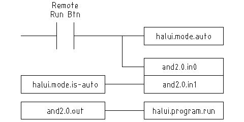
This document is aimed at people who already know how to do this kind of hardware system integration, but who do not know how to connect the hardware to LinuxCNC. See the Remote Start Example section in the HAL UI Examples documentation.
The traditional hardware design as described above ends at the edge of the main control. Outside the control are a bunch of relatively simple boxes, connected together to do whatever is needed. Inside, the control is a big mystery — one huge black box that we hope works.
HAL extends this traditional hardware design method to the inside of the big black box. It makes device drivers and even some internal parts of the controller into smaller black boxes that can be interconnected and even replaced just like the external hardware. It allows the system wiring diagram to show part of the internal controller, rather than just a big black box. And most importantly, it allows the integrator to test and modify the controller using the same methods he would use on the rest of the hardware.
Terms like motors, amps, and encoders are familiar to most machine integrators. When we talk about using extra flexible eight conductor shielded cable to connect an encoder to the servo input board in the computer, the reader immediately understands what it is and is led to the question, what kinds of connectors will I need to make up each end. The same sort of thinking is essential for the HAL but the specific train of thought may take a bit to get on track. Using HAL words may seem a bit strange at first, but the concept of working from one connection to the next is the same.
This idea of extending the wiring diagram to the inside of the controller is what HAL is all about. If you are comfortable with the idea of interconnecting hardware black boxes, you will probably have little trouble using HAL to interconnect software black boxes.
2. HAL Concepts
This section is a glossary that defines key HAL terms but it is a bit different than a traditional glossary because these terms are not arranged in alphabetical order. They are arranged by their relationship or flow in the HAL way of things.
- Component
-
When we talked about hardware design, we referred to the individual pieces as parts, building blocks, black boxes, etc. The HAL equivalent is a component or HAL component. (This document uses HAL component when there is likely to be confusion with other kinds of components, but normally just uses component.) A HAL component is a piece of software with well-defined inputs, outputs, and behavior, that can be installed and interconnected as needed.
- Parameter
-
Many hardware components have adjustments that are not connected to any other components but still need to be accessed. For example, servo amps often have trim pots to allow for tuning adjustments, and test points where a meter or scope can be attached to view the tuning results. HAL components also can have such items, which are referred to as parameters. There are two types of parameters: Input parameters are equivalent to trim pots - they are values that can be adjusted by the user, and remain fixed once they are set. Output parameters cannot be adjusted by the user - they are equivalent to test points that allow internal signals to be monitored.
- Pin
-
Hardware components have terminals which are used to interconnect them. The HAL equivalent is a pin or HAL pin. (HAL pin is used when needed to avoid confusion.) All HAL pins are named, and the pin names are used when interconnecting them. HAL pins are software entities that exist only inside the computer.
- Physical_Pin
-
Many I/O devices have real physical pins or terminals that connect to external hardware, for example the pins of a parallel port connector. To avoid confusion, these are referred to as physical pins. These are the things that stick out into the real world.
- Signal
-
In a physical machine, the terminals of real hardware components are interconnected by wires. The HAL equivalent of a wire is a signal or HAL signal. HAL signals connect HAL pins together as required by the machine builder. HAL signals can be disconnected and reconnected at will (even while the machine is running).
- Type
-
When using real hardware, you would not connect a 24 volt relay output to the +/-10V analog input of a servo amp. HAL pins have the same restrictions, which are based upon their type. Both pins and signals have types, and signals can only be connected to pins of the same type. Currently there are 4 types, as follows:
-
bit - a single TRUE/FALSE or ON/OFF value
-
float - a 64 bit floating point value, with approximately 53 bits of resolution and over 1000 bits of dynamic range.
-
u32 - a 32 bit unsigned integer, legal values are 0 to 4,294,967,295
-
s32 - a 32 bit signed integer, legal values are -2,147,483,647 to +2,147,483,647
-
- Function
-
Real hardware components tend to act immediately on their inputs. For example, if the input voltage to a servo amp changes, the output also changes automatically. However software components cannot act automatically. Each component has specific code that must be executed to do whatever that component is supposed to do. In some cases, that code simply runs as part of the component. However in most cases, especially in realtime components, the code must run in a specific sequence and at specific intervals. For example, inputs should be read before calculations are performed on the input data, and outputs should not be written until the calculations are done. In these cases, the code is made available to the system in the form of one or more functions. Each function is a block of code that performs a specific action. The system integrator can use threads to schedule a series of functions to be executed in a particular order and at specific time intervals.
- Thread
-
A thread is a list of functions that runs at specific intervals as part of a realtime task. When a thread is first created, it has a specific time interval (period), but no functions. Functions can be added to the thread, and will be executed in order every time the thread runs.
As an example, suppose we have a parport component named hal_parport. That component defines one or more HAL pins for each physical pin. The pins are described in that component’s doc section: their names, how each pin relates to the physical pin, are they inverted, can you change polarity, etc. But that alone doesn’t get the data from the HAL pins to the physical pins. It takes code to do that, and that is where functions come into the picture. The parport component needs at least two functions: one to read the physical input pins and update the HAL pins, the other to take data from the HAL pins and write it to the physical output pins. Both of these functions are part of the parport driver.
3. HAL components
Each HAL component is a piece of software with well-defined inputs, outputs, and behavior, that can be installed and interconnected as needed. This section lists some of the available components and a brief description of what each does. Complete details for each component are available later in this document.
3.1. External Programs with HAL hooks
- motion
-
A realtime module that accepts NML
[Neutral Message Language provides a mechanism for handling multiple types of messages in the same buffer as well as simplifying the interface for encoding and decoding buffers in neutral format and the configuration mechanism.]
motion commands and interacts with HAL - iocontrol
-
A user space module that accepts NML I/O commands and interacts with HAL
- classicladder
-
A PLC using HAL for all I/O
- halui
-
A user space program that interacts with HAL and sends NML commands, it is intended to work as a full User Interface using external knobs & switches
3.2. Internal Components
- stepgen
-
Software step pulse generator with position loop. See section [sec:stepgen]
- encoder
-
Software based encoder counter. See section [sec:encoder]
- pid
-
Proportional/Integral/Derivative control loops. See section [sec:pid]
- siggen
-
A sine/cosine/triangle/square wave generator for testing. See section [sec:siggen]
- supply
-
a simple source for testing
3.3. Hardware Drivers
- hal_ax5214h
-
A driver for the Axiom Measurement & Control AX5241H digital I/O board
- hal_gm
-
General Mechatronics GM6-PCI board
- hal_m5i20
-
Mesa Electronics 5i20 board
- hal_motenc
-
Vital Systems MOTENC-100 board
- hal_parport
-
PC parallel port.
- hal_ppmc
-
Pico Systems family of controllers (PPMC, USC and UPC)
- hal_stg
-
Servo To Go card (version 1 & 2)
- hal_vti
-
Vigilant Technologies PCI ENCDAC-4 controller
3.4. Tools and Utilities
- halcmd
-
Command line tool for configuration and tuning. See section [sec:halcmd]
- halmeter
-
A handy multimeter for HAL signals. See section [sec:halmeter].
- halscope
-
A full featured digital storage oscilloscope for HAL signals. See the Halscope section.
Each of these building blocks is described in detail in later chapters.
4. Timing Issues In HAL
Unlike the physical wiring models between black boxes that we have said that HAL is based upon, simply connecting two pins with a hal-signal falls far short of the action of the physical case.
True relay logic consists of relays connected together, and when a contact opens or closes, current flows (or stops) immediately. Other coils may change state, etc, and it all just happens. But in PLC style ladder logic, it doesn’t work that way. Usually in a single pass through the ladder, each rung is evaluated in the order in which it appears, and only once per pass. A perfect example is a single rung ladder, with a NC contact in series with a coil. The contact and coil belong to the same relay.
If this were a conventional relay, as soon as the coil is energized, the contacts begin to open and de-energize it. That means the contacts close again, etc, etc. The relay becomes a buzzer.
With a PLC, if the coil is OFF and the contact is closed when the PLC begins to evaluate the rung, then when it finishes that pass, the coil is ON. The fact that turning on the coil opens the contact feeding it is ignored until the next pass. On the next pass, the PLC sees that the contact is open, and de-energizes the coil. So the relay still switches rapidly between on and off, but at a rate determined by how often the PLC evaluates the rung.
In HAL, the function is the code that evaluates the rung(s). In fact, the HAL-aware realtime version of ClassicLadder exports a function to do exactly that. Meanwhile, a thread is the thing that runs the function at specific time intervals. Just like you can choose to have a PLC evaluate all its rungs every 10 ms, or every second, you can define HAL threads with different periods.
What distinguishes one thread from another is not what the thread does - that is determined by which functions are connected to it. The real distinction is simply how often a thread runs.
In LinuxCNC you might have a 50 us thread and a 1 ms thread. These would be created based on BASE_PERIOD and SERVO_PERIOD, the actual times depend on the values in your ini file.
The next step is to decide what each thread needs to do. Some of those decisions are the same in (nearly) any LinuxCNC system—For instance, motion-command-handler is always added to servo-thread.
Other connections would be made by the integrator. These might include hooking the STG driver’s encoder read and DAC write functions to the servo thread, or hooking stepgen’s function to the base-thread, along with the parport function(s) to write the steps to the port.