1. Tool Length Offsets
1.1. Touch Off
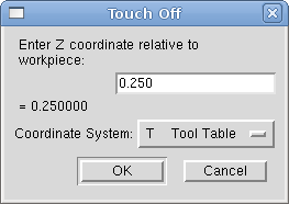
Using the Touch Off Screen in the AXIS interface you can update the tool table automatically.
Typical steps for updating the tool table:
-
After homing load a tool with Tn M6 where n is the tool number.
-
Move tool to an established point using a gauge or take a test cut and measure.
-
Click the "Touch Off" button in the Manual Control tab (or hit the End button on your keyboard).
-
Select Tool Table in the Coordinate System drop down box.
-
Enter the gauge or measured dimension and select OK.
The Tool Table will be changed with the correct Z length to make the DRO display the correct Z position and a G43 command will be issued so the new tool Z length will be in effect. Tool table touch off is only available when a tool is loaded with Tn M6.
1.2. Using G10 L1/L10/L11
The G10 L1/L10/L11 commands can be used to set tool table offsets: (these are just quick summaries, see the G code section for full details)
2. Tool Table
The Tool Table is a text file that contains information about each tool. The file is located in the same directory as your configuration and is called tool.tbl. The tools might be in a tool changer or just changed manually. The file can be edited with a text editor or be updated using G10 L1. See the Lathe Tool Table Section for an example of the lathe tool table format. The maximum number of entries in the tool table is 56. The maximum tool and pocket number is 99999.
The Tool Editor or a text editor can be used to edit the tool table. If you use a text editor make sure you reload the tool table in the GUI.
2.1. Tool Table Format
| T# | P# | X | Y | Z | A | B | C | U | V | W | Dia | FA | BA | Ori | Rem |
|---|---|---|---|---|---|---|---|---|---|---|---|---|---|---|---|
; |
(no data after opening semicolon) |
||||||||||||||
T1 |
P17 |
X0 |
Y0 |
Z0 |
A0 |
B0 |
C0 |
U0 |
V0 |
W0 |
D0 |
I0 |
J0 |
Q0 |
;rem |
T2 |
P5 |
X0 |
Y0 |
Z0 |
A0 |
B0 |
C0 |
U0 |
V0 |
W0 |
D0 |
I0 |
J0 |
Q0 |
;rem |
T3 |
P12 |
X0 |
Y0 |
Z0 |
A0 |
B0 |
C0 |
U0 |
V0 |
W0 |
D0 |
I0 |
J0 |
Q0 |
;rem |
In general, the new tool table line format is:
-
; - opening semicolon, no data
-
T - tool number, 0-99999 (tool numbers must be unique)
-
P - pocket number, 1-99999 (pocket numbers must be unique)
-
X..W - tool offset on specified axis - floating-point
-
D - tool diameter - floating-point, absolute value
-
I - front angle (lathe only) - floating-point
-
J - back angle (lathe only) - floating-point
-
Q - tool orientation (lathe only) - integer, 0-9
-
; - beginning of comment or remark - text
The file consists of one opening semicolon on the first line,
followed by up to a maximum of 56 tool entries.
[Although tool numbers up to 99999 are allowed, the number
of entries in the tool table, at the moment, is still limited to a
maximum of 56 tools for technical reasons. The LinuxCNC developers plan
to remove that limitation eventually. If you have a very large
tool changer, please be patient.]
Earlier versions of LinuxCNC had two different tool table formats for mills and lathes, but since the 2.4.x release, one tool table format is used for all machines. Just ignore the parts of the tool table that don’t pertain to your machine, or which you don’t need to use.
Each line of the tool table file after the opening semicolon contains the data for one tool. One line may contain as many as 16 entries, but will likely contain much fewer.
The units used for the length, diameter, etc., are in machine units.
You will probably want to keep the tool entries in ascending order, especially if you are going to be using a randomizing tool changer. Although the tool table does allow for tool numbers in any order.
Each line may have up to 16 entries. The first two entries are required. The last entry (a remark or comment, preceded by a semicolon) is optional. It makes reading easier if the entries are arranged in columns, as shown in the table, but the only format requirement is that there be at least one space or tab after each of the entries on a line and a newline character at the end of each entry.
The meanings of the entries and the type of data to be put in each are as follows.
The T column contains the number (unsigned integer) which represents a code number for the tool. The user may use any code for any tool, as long as the codes are unsigned integers.
The P column contains the number (unsigned integer) which represents the pocket number (slot number) of the tool changer slot where the tool can be found. The entries in this column must all be different.
The pocket numbers will typically start at 1 and go up to the highest available pocket on your tool changer. But not all tool changers follow this pattern. Your pocket numbers will be determined by the numbers that your tool changer uses to refer to the pockets. So all this is to say that the pocket numbers you use will be determined by the numbering scheme used in your tool changer, and the pocket numbers you use must make sense on your machine.
The Data Offset columns (XYZABCUVW) contain real numbers which represent tool offsets in each axis. This number will be used if tool length offsets are being used and this tool is selected. These numbers can be positive, zero, or negative, and are in fact completely optional. Although you will probably want to make at least one entry here, otherwise there would be little point in making an entry in the tool table to begin with.
In a typical mill, you probably want an entry for Z (tool length offset). In a typical lathe, you probably want an entry for X (X tool offset) and Z (Z tool offset). In a typical mill using cutter diameter compensation (cutter comp), you probably also want to add an entry for D (cutter diameter). In a typical lathe using tool nose diameter compensation (tool comp), you probably also want to add an entry for D (tool nose diameter).
A lathe also requires some additional information to describe the shape and orientation of the tool. So you probably want to have entries for I (tool front angle) and J (tool back angle). You probably also want an entry for Q (tool orientation).
A complete description of the lathe entries can be found in the lathe section of the user manual here.
The Diameter column contains a real number. This number is used only if cutter compensation is turned on using this tool. If the programmed path during compensation is the edge of the material being cut, this should be a positive real number representing the measured diameter of the tool. If the programmed path during compensation is the path of a tool whose diameter is nominal, this should be a small number (positive or negative, but near zero) representing only the difference between the measured diameter of the tool and the nominal diameter. If cutter compensation is not used with a tool, it does not matter what number is in this column.
The Comment column may optionally be used to describe the tool. Any type of description is OK. This column is for the benefit of human readers only. The comment must be preceded by a semicolon.
2.2. Tool Changers
LinuxCNC supports three types of tool changers: manual, random location and fixed location. Information about configuring an LinuxCNC tool changer is in the Integrator Manual.
Manual tool changer (you change the tool by hand) is treated like a fixed location tool changer and the P number is ignored. Using the manual tool changer only makes sense if you have tool holders that remain with the tool (Cat, NMTB, Kwik Switch etc.) when changed thus preserving the location of the tool to the spindle. Machines with R-8 or router collet type tool holders do not preserve the location of the tool and the manual tool changer should not be used.
Fixed location tool changers always return the tools to a fixed position in the tool changer. This would also include designs like lathe turrets. When LinuxCNC is configured for a fixed location tool changer the P number is ignored (but read, preserved and rewritten) by LinuxCNC, so you can use P for any bookkeeping number you want.
Random location tool changers swap the tool in the spindle with the one in the changer. With this type of tool changer the tool will always be in a different pocket after a tool change. When a tool is changed LinuxCNC rewrites the pocket number to keep track of where the tools are. T can be any number but P must be a number that makes sense for the machine.
3. Cutter Compensation
Cutter Compensation allows the programmer to program the tool path without knowing the exact tool diameter. The only caveat is the programmer must program the lead in move to be at least as long as the largest tool radius that might be used.
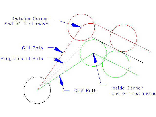
There are two possible paths the cutter can take while cutter compensation is on to the left or right side of a line when facing the direction of cutter motion from behind the cutter. To visualize this imagine you were standing on the part walking behind the tool as it progresses across the part. G41 is your left side of the line and G42 is the right side of the line.
The end point of each move depends on the next move. If the next move creates an outside corner the move will be to the end point of the compensated cut line. If the next move creates in an inside corner the move will stop short so to not gouge the part. The following figure shows how the compensated move will stop at different points depending on the next move.
3.1. Overview
Cutter compensation uses the data from the tool table to determine the offset needed. The data can be set at run time with G10 L1.
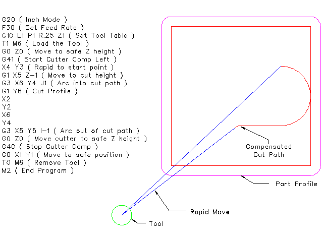
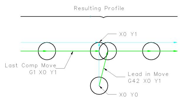
Any move that is long enough to perform the compensation will work as the entry move. The minimum length is the cutter radius. This can be a rapid move above the work piece. If several rapid moves are issued after a G41/42 only the last one will move the tool to the compensated position.
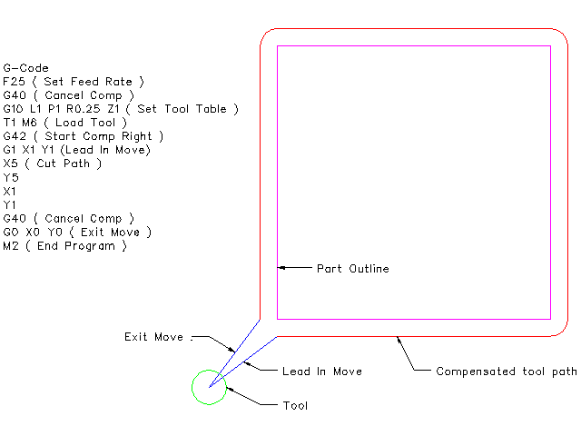
In the following figure you can see that the entry move is compensated to the right of the line. This puts the center of the tool to the right of X0 in this case. If you were to program a profile and the end is at X0 the resulting profile would leave a bump due to the offset of the entry move.
Z axis motion may take place while the contour is being followed in the XY plane. Portions of the contour may be skipped by retracting the Z axis above the part and by extending the Z-axis at the next start point.
Rapid moves may be programed while compensation is turned on.
-
Start a program with G40 to make sure compensation is off.