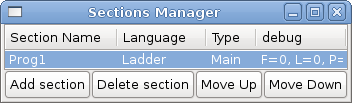
 Figure: Sections Manager Default Window
Classic Ladder is a free implementation of a ladder interpreter, released under the LGPL. It has been written by Marc Le Douarain.
He describes the beginning of the project on his website Original project homepage:
“I decided to program a ladder language only for test purposes at the start, in February 2001. It was planned, that I would have to participate to a new product after leaving the enterprise in which I was working at that time. And I was thinking that to have a ladder language in those products could be a nice option to considerate. And so I started to code the first lines for calculating a rung with minimal elements and displaying dynamically it under Gtk, to see if my first idea to realize all this works.
And as quickly I've found that it advanced quite well, I've continued with more complex elements : timer, multiples rungs, etc...
Voila, here is this work... and more : I've continued to add features since then.”
Classic Ladder has been adapted to work with EMC2's HAL, and is currently being distributed along with EMC2. If there are issues/problems/bugs please report them to the Enhanced Machine Controller project.
Classic Ladder is a type of programming language originally implemented on industrial PLC's (it's called Ladder Programming). It is based on the concept of relay contacts and coils, and can be used to construct logic checks and functions in a manner that is familiar to many systems integrators. It is important to know how ladder programs are evaluated when running:
It seems natural that each line would be evaluated left to right then the next line down etc-but it doesn't work this way. ALL the inputs are read, ALL the logic is figured out, then ALL the outputs are set. This can presents a problem in certain circumstance if the output of one line feeds the input of another. Another gotcha with ladder programming is the "Last One Wins" rule. If you have the same output in different locations of your ladder the state of the last one will be what the output is set to.
Classic Ladder version 7.124 has been adapted for EMC 2.3 This document describes that version.
The most common language used when working with Classic Ladder is 'ladder'. Classic Ladder also supports Sequential Function Chart (Grafcet).
There are 2 components to Classic Ladder.
Typically classic ladder components are placed in the custom.hal file if your working from a Stepconf generated configuration. These must not be placed in the custom_postgui.hal file or the Ladder Editor menu will be grayed out.
Ladder files (.clp) must not contain any blank spaces in the name.
Loading the Classic Ladder real time module (classicladder_rt) is possible from a hal file, or directly using a halcmd instruction. The first line loads real time the Classic Ladder module. The second line adds the function classicladder.0.refresh to the servo thread. This line makes Classic Ladder update at the servo thread rate.
loadrt classicladder_rt
addf classicladder.0.refresh servo-thread
The speed of the thread that Classic Ladder is running in directly effects the responsiveness to inputs and outputs. If you can turn a switch on and off faster than Classic Ladder can notice it then you may need to speed up the thread. The fastest that Classic Ladder can update the rungs is one millisecond. You can put it in a faster thread but it will not update any faster. If you put it in a slower then one microsecond thread then Classic Ladder will update the rungs slower. The current scan time will be displayed on the section display, it is rounded to microseconds. If the scan time is longer than one millisecond you may want to shorten the ladder or put it in a slower thread.
It is possible to configure the number of each type of ladder object while loading the Classic Ladder real time module. If you do not configure the number of ladder objects Classic Ladder will use the default values.
| Object Name | Variable Name | Default Value |
| Number of rungs | (numRungs) | 100 |
| Number of bits | (numBits) | 20 |
| Number of word variables | (numWords) | 20 |
| Number of timers | (numTimers) | 10 |
| Number of timers IEC | (numTimersIec) | 10 |
| Number of monostables | (numMonostables) | 10 |
| Number of counters | (numCounters) | 10 |
| Number of hal inputs bit pins | (numPhysInputs) | 15 |
| Number of hal output bit pins | (numPhysOutputs) | 15 |
| Number of arithmetic expressions | (numArithmExpr) | 50 |
| Number of Sections | (numSections) | 10 |
| Number of Symbols | (numSymbols) | Auto |
| Number of S32 inputs | (numS32in) | 10 |
| Number of S32 outputs | (numS32out) | 10 |
| Number of Float inputs | (numFloatIn) | 10 |
| Number of Float outputs | (numFloatOut) | 10 |
Objects of most interest are numPhysInputs, numPhysOutputs, numS32in, and numS32out.
Changing these numbers will change the number of HAL bit pins available. numPhysInputs and numPhysOutputs control how many HAL bit (on/off) pins are available. numS32in and numS32out control how many HAL signed integers (+- integer range) pins are available.
For example (you don't need all of these to change just a few):
loadrt classicladder_rt numRungs=12 numBits=100 numWords=10 numTimers=10 numMonostables=10 numCounters=10 numPhysInputs=10 numPhysOutputs=10 numArithmExpr=100 numSections=4 numSymbols=200 numS32in=5 numS32out=5
To load the default number of objects:
loadrt classicladder_rt
Classic Ladder hal commands must executed before the GUI loads or the menu item Ladder Editor will not function. If you used the Stepper Config Wizard place any Classic Ladder hal commands in the custom.hal file.
To load the user module:
loadusr classicladder
To load a ladder file:
loadusr classicladder myladder.clp
Classic Ladder Loading Options
To use Classic Ladder with HAL without EMC. The -w tells HAL not to close down the HAL environment until Classic Ladder is finished.
loadusr -w classicladder
If you first load ladder program with the --nogui option then load Classic Ladder again with no options the GUI will display the last loaded ladder program.
In AXIS you can load the GUI from File/Ladder Editor...
If you load Classic Ladder with the GUI it will display two windows: section display, and section manager.
When you first start up Classic Ladder you get an empty Sections Manager window.
This window allows you to name, create or delete sections and choose what language that section uses. This is also how you name a subroutine for call coils.
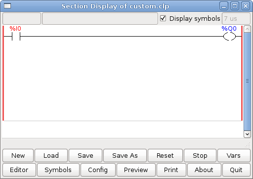
When you first start up Classic Ladder you get an empty Section Display window.
Most of the buttons are self explanatory:
The Vars button is for looking at variables, toggle it to display one, the other, both, then none of the windows.
The Config button is used for modbus and shows the max number of ladder elements that was loaded with the real time module.
The Symbols button will display an editable list of symbols for the variables (hint you can name the inputs, outputs, coils etc).
The Quit button will shut down the user program meaning Modbus and the display- the real time ladder program will still run in the back ground.
The check box at the top right allows you to select whether variable names or symbol names are displayed
You might notice that there is a line under the ladder program display that reads "Project failed to load..." That is the status bar that gives you info about elements of the ladder program that you click on in the display window. This status line will now display HAL signal names for variables %I, %Q and the first %W (in an equation) You might see some funny labels, such as (103) in the rungs. This is displayed (on purpose) because of an old bug- when erasing elements older versions sometimes didn't erase the object with the right code. You might have noticed that the long horizontal connection button sometimes didn't work in the older versions. This was because it looked for the 'free' code but found something else. The number in the brackets is the unrecognized code. The ladder program will still work properly, to fix it erase the codes with the editor and save the program.
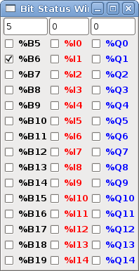
This are two variable windows: bool and signed integer. the vars button is in the section display window, toggle the Vars button to display one, the other, both, then none of the windows.
The Bool window displays some of all the bool (on/off) variable data . Notice all variable start with the % sign. The %I variable represents HAL input bit pins. The %Q represents the relay coil and HAL output bit pins. The %B represents an internal relay coil or internal contact The three edit areas at the top allow you to select what 15 variable will be displayed in each column. For instance if there were 30 %B variable and you entered 5 at the top of the column, variable %B5 to %B19 would be displayed. The check boxes allow you to set and unset %B variables manually as long as the ladder program isn't setting them as outputs. Any Bits that are set as outputs by the program when Classic Ladder is running can not be changed and will be displayed as checked if on and unchecked if off.
The Watch Window displays variable status. The edit box beside it is the number stored in the variable and the drop-down box beside that allow you to choose whether the number to be displayed in hex, decimal or binary. If there are symbol names defined in the symbols window for the word variables showing and the 'display symbols' checkbox is checked the the section display window, symbol names will be displayed. To change the variable displayed type the variable number eg. %W2 (if display symbols check box is not checked) or symbol name (if the display symbols checkbox is checked) over an existing variable number/name and press the Enter Key.
This is a list of 'symbol' names to use instead of variable names to be displayed in the section window when the 'display symbols' check box is checked. You add the variable name (remember the '%' symbol and capital letters), symbol name . If the variable can have a HAL signal connected to it (%I, %Q, and %W-if you have loaded s32 pin with the real time module) then the comment section will show the current HAL signal name or lack there of. symbol names should be kept short to display better. keep in mind that you can display the longer HAL signal name of %I, %Q and %W variable by clicking on them in the section window. Between the two on should be able to keep track of what the ladder program is connected to!
Starting from the top left image:
A short description of each of the buttons:
The config window shows the current project status and has the Modbus setup tabs.
Represent switches or relay contacts. They are controlled by the variable letter and number assigned to them.
The variable letter can be B, I, or Q and the number can be up to a three digit number eg. %I2, %Q3, or %B123. Variable I is controlled by a Hal input pin with a corresponding number . Variable B is for internal contacts, controlled by a B coil with a corresponding number. Variable Q is controlled by a Q coil with a corresponding number. (like a relay with multiple contacts). Eg. if HAL pin classicladder.0.in-00 is true then %I0 N.O. contact would be on (closed, true, whatever you like to call it). If %B7 coil is 'energized' (on, true, etc) then %B7 N.O. contact would be on. If %Q1 coil is 'energized' then %Q1 N.O. contact would be on (and HAL pin classicladder.0.out-01 would be true.)
Represent new count down timers! IEC Timers replace Timers and Monostables.
IEC Timers have 2 contacts.
There are three modes - TON, TOF, TP.
The time intervals can be set in multiples of 100ms, seconds, or minutes.
There are also Variables for IEC timers that can be read and/or written to in compare or operate blocks.
Represent count down timers. This is deprecated and replaced by IEC Timers.
Timers have 4 contacts.
The timer base can be multiples of milliseconds, seconds, or minutes.
There are also Variables for timers that can be read and/or written to in compare or operate blocks.
Represent are one-shot timers. This is deprecated and replaced by IEC Timers.
Monostables have 2 contacts I and R.
The I contact is rising edge sensitive meaning it starts the timer only when changing from false to true (or off to on). While the timer is running the I contact can change with no effect to the running timer. R will be true and stay true till the timer finishes counting to zero. The timer base can be multiples of milliseconds, seconds, or minutes.
There are also Variables for monostables that can be read and/or written to in compare or operate blocks.
- Represent up/down counters.
- There are 7 contacts:
The up and down count contacts are edge sensitive meaning they only count when the contact changes from false to true (or off to on if you rather).
The range is 0 to 9999.
There are also Variables for counters that can be read and/or written to in compare or operate blocks.
For arithmetic comparison. eg Is variable %XXX = to this number (or evaluated number)
The compare block will be true when comparison is true. you can use most math symbols +,-,*,/,=,<,>,<=,>=,(,),^ (exponent),% (modulus),& (and),| (or),! (not). - You can also use math functions. They are ABS (absolute), MOY (french for average) ,AVG (average). eg ABS(%W2)=1, MOY(%W1,%W2)<3. No spaces are allowed in the comparison equation. For example %C0.V>%C0.P is a valid comparison expression while %C0.V > %CO.P is not a valid expression.
There is a list of Variables down the page that can be used for reading writing to ladder objects. When a new compare block is opened be sure and delete the # symbol when you enter a compare.
To find out if word variable #1 is less than 2 times the current value of counter #0 the syntax would be:
%W1<2*%C0.V
To find out if S32in bit 2 is equal to 10 the syntax would be:
%IW2=10
Note: Compare uses the arithmetic equals not the double equals that programmers are use to.
For variable assignment. eg assign this number (or evaluated number) to this variable %xxx there are two math functions MINI and MAXI that check a variable for maximum (0x80000000) and minimum values (0x07FFFFFFF) (think signed values) and keeps them from going beyond.
When a new variable assignment block is opened be sure and delete the # symbol when you enter an assignment.
To assign a value of 10 to the timer preset of IEC Timer 0 the syntax would be:
%TM0.P=10
To assign the value of 12 to S32out bit 3 the syntax would be:
%QW3=12
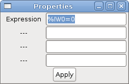
The following figure shows an Assignment and a Comparison Example. %QW0 is a S32out bit and %IW0 is a S32in bit. In this case the HAL pin classicladder.0.s32out-00 will be set to a value of 5 and when the HAL pin classicladder.0.s32in-00 is 0 the HAL pin classicladder.0.out-00 will be set to True.
Coils represent relay coils. They are controlled by the variable letter and number assigned to them.
The variable letter can be B or Q and the number can be up to a three digit number eg. %Q3, or %B123. Q coils control HAL out pins. eg if &Q15 is energized then HAL pin classicladder.0.out-15 will be true. B coils are internal coils used to control program flow.
***WARNING*** if you use a N.C. contact with a N.C. coil the logic will work (when the coil is energized the contact will be closed) but that is really hard to follow!
A JUMP COIL is used to 'JUMP' to another section-like a goto in BASIC programming language.
If you look at the top left of the sections display window you will see a small label box and a longer comment box beside it. Now go to Editor->Modify then go back to the little box, type in a name.
Go ahead and add a comment in the comment section. This label name is the name of this rung only and is used by the JUMP COIL to identify where to go.
When placing a JUMP COIL add it in the right most position and change the label to the rung you want to JUMP to.
A CALL COIL is used to go to a subroutine section then return-like a gosub in BASIC programming language.
If you go to the sections manager window hit the add section button. You can name this section, select what language it will use (ladder or sequential), and select what type (main or subroutine).
Select a subroutine number (SR0 for example). An empty section will be displayed and you can build your subroutine.
When you've done that, go back to the section manager and click on the your main section (default name prog1).
Now you can add a CALL COIL to your program. CALL COILs are to be placed at the right most position in the rung.
Remember to change the label to the subroutine number you choose before.
These Variables are used in COMPARE or OPERATE to get information about, or change specs of, ladder objects Such as changing a counter preset, or seeing if the a timer is done running.
List of variables :
* WARNING -These is probably the least used/known about feature of Classic Ladder. Sequential programming is used to make sure a series of ladder events always happen in a prescribed order. Sequential programs do not work alone-there is always a ladder program as well that controls the variables. Here are the basic rules governing sequential programs:
This is the SEQUENTIAL editor window Starting from the top left image: Selector arrow , Eraser Ordinary step , Initial (Starting) step Transition , Step and Transition Transition Link-Downside , Transition Link-Upside Pass-through Link-Downside , Pass-through Link-Upside Jump Link Comment Box [show sequential program]
To use links you must have steps already placed , select the type of link , then select the two steps or transactions one at a time- It takes practice!
With sequential programming: The variable %Xxxx (eg. %X5) is used to see if a step is active. The variable %Xxxx.V (eg. %X5.V) is used to see how long the step has been active. The %X and %X.v variables are use in LADDER logic. The variables assigned to the transitions (eg. %B) control whether the logic will pass to the next step. After a step has become active the transition variable that caused it to become active has no control of it anymore. The last step has to JUMP LINK back (only to the beginning step?)
Things to consider:
To get MODBUS to initialize you must specify that when loading the Classic Ladder userspace program eg. loadusr -w classicladder --modmaster myprogram.clp (assuming myprogram.clp is present -w makes HAL wait till you close Classic Ladder before closing realtime session) my idea behind this is to get a working modbus solution out there then we can decide how it should be done in the best way. As it stands now Classic Ladder also loads a TCP modbus slave (if you add --modserver on command line) - I have not tested this nor have I tested the TCP modbus master. I have done some testing with the serial port and had to add some functions to get it to talk to my VFD -but it does work. Modbus function 1,2,3,4,5,6,8,15,16 (read coils,read inputs, read holding registers, read input registers, write single coils, write single register, echo test, write multiple coils, write multiply registers) are currently available. If you do not specify a --modmaster when loading the Classic Ladder user program this (next) page will not be displayed.
In the example above: Port number- for my computer /dev/ttyS0 was my serial port
The serial speed is set to 9600 baud.
Slave address is set to 12 ( on my VFD I can set this from 1-31, meaning I can talk to 31 VFDs maximum on one system)
The first line is set up for 8 input bits starting at the first register number (register 1) so register numbers 1-8 and maps them on to Classic Ladder's %B variables starting at %B1 ending at %B8.
The second line is set for 2 output bits starting at the ninth register number (register 9) so register numbers 9-10 and maps them on to Classic Ladder's %Q variables starting at %Q9 ending at %Q10.
The third line is set to write 2 registers (16 bit each) starting at the 0th register number (register 0) so register numbers 0-1 and maps them on to Classic Ladder's %W variables starting at %W0 ending at %W1
It's easy to make an off-by-one error as sometimes the modbus elements are referenced starting at one rather then 0 (actually by the standard that is the way it's supposed to be!) You can use the modbus element offset radio button to help with this.
The documents for your modbus slave device will tell you how the registers are set up- there is no standard way.
The SERIAL PORT, PORT SPEED, PAUSE, and DEBUG level are editable for changes (when you close the config window values are applied though Radio buttons apply immediately)
To use the echo function select the echo function and add the slave number you wish to test. You don't need to specify any variables.
The number 257 will be sent to the slave number you specified and the slave should send it back. you will need to have Classic Ladder running in a terminal to see the message.
Serial:
Info on modbus protocol are available here:
http://www.sourceforge.net/projects/jamod
http://www.modicon.com/techpubs/toc7.html
If there is a communication error, a warning window will pop up (if the GUI is running) and %E0 will be true. Modbus will continue to try and communicate. The %E0 could be used to make a decision based on the error. A timer could be used to stop the machine if timed out etc.
In this section we will cover the steps needed to add Classic Ladder to a Stepconf Wizard generated config. On the advanced Configuration Options page of Stepconf Wizard check off "Include Classic Ladder PLC"
If you used the Stepconf Wizard to add Classic Ladder you can skip this step.
To manually add Classic Ladder you must first add the modules. This is done by adding a couple of lines to the custom.hal file.
This line loads the real time module:
loadrt classicladder_rt
This line adds the Classic Ladder function to the servo thread:
addf classicladder.0.refresh servo-thread
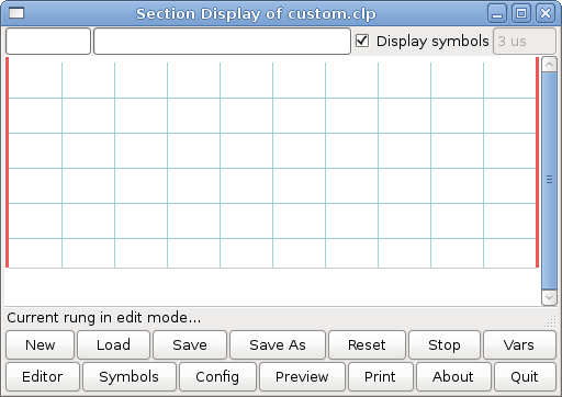
Now start up your config and select File/Ladder Editor... to open up the Classic Ladder GUI. You should see a blank Section Display and Sections Manager window as shown above. In the Section Display window open the Editor. In the Editor window select Modify. Now a Properties window pops up and the Section Display shows a grid. The grid is one rung of ladder. The rung can contain branches. A simple rung has one input, a connector line and one output.
Now click on the N.O. Input in the Editor Window.
Now click in the upper left grid to place the N.O. Input into the ladder.
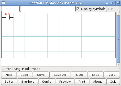
Repeat the above steps to add a N.O. Output to the upper right grid and use the Horizontal Connection to connect the two. It should look like the following. If not use the Eraser to remove unwanted sections.
Now click on the OK button in the Editor window. Now your Section Display should look like this.
To save the new file select Save As and give it a name. The .clp extension will be added automatically. It should default to the running config directory as the place to save it.
Again if you used the Stepconf Wizard to add Classic Ladder you can skip this step.
To manually add a ladder you need to add add a line to your custom.hal file that will load your ladder file. Close your EMC2 session and add this line to your custom.hal file.
loadusr -w classicladder --nogui MyLadder.clp
Now if you start up your EMC2 config your ladder program will be running as well. If you select File/Ladder Editor... the program you created will show up in the Section Display window.