 Figure: Velocity Example
All of these examples assume you are starting with a stepconf based configuration and have two threads base-thread and servo-thread. The stepconf wizard will create an empty custom.hal and a custom_postgui.hal file. The custom.hal file will be loaded after the configuration hal file and the custom_postgui.hal file is loaded after the GUI has been loaded.
In this example it is assumed that your "rolling your own" configuration and wish to add the HAL Manual Toolchange window. The HAL Manual Toolchange is primarily useful if you have presettable tools and you store the offsets in the tool table. If you need to touch off for each tool change then it is best just to split up your g code. To use the HAL Manual Toolchange window you basically have to load the hal manualtoolchange component then send the iocontrol "tool change" to the hal manualtoolchange "change" and send the hal manualtoolchange "changed" back to the iocontrol "tool changed".
This is an example of with the HAL Manual Toolchange from the stepconf wizard
loadusr -W hal_manualtoolchange
net tool-change iocontrol.0.tool-change => hal_manualtoolchange.change
net tool-changed iocontrol.0.tool-changed <= hal_manualtoolchange.changed
net tool-number iocontrol.0.tool-prep-number => hal_manualtoolchange.number
net tool-prepare-loopback iocontrol.0.tool-prepare => iocontrol.0.tool-prepared
This is an example of without the HAL Manual Toolchange from the stepconf wizard
net tool-number <= iocontrol.0.tool-prep-number
net tool-change-loopback iocontrol.0.tool.-change => iocontrol.0.tool-changed
net tool-prepare-loopback iocontrol.0.tool-prepare => iocontrol.0.tool-prepared
This example uses "ddt", "mult2" and "abs" to compute the velocity of a single axis. For more information on the real time components see the man pages or the Realtime Components section ([->]).
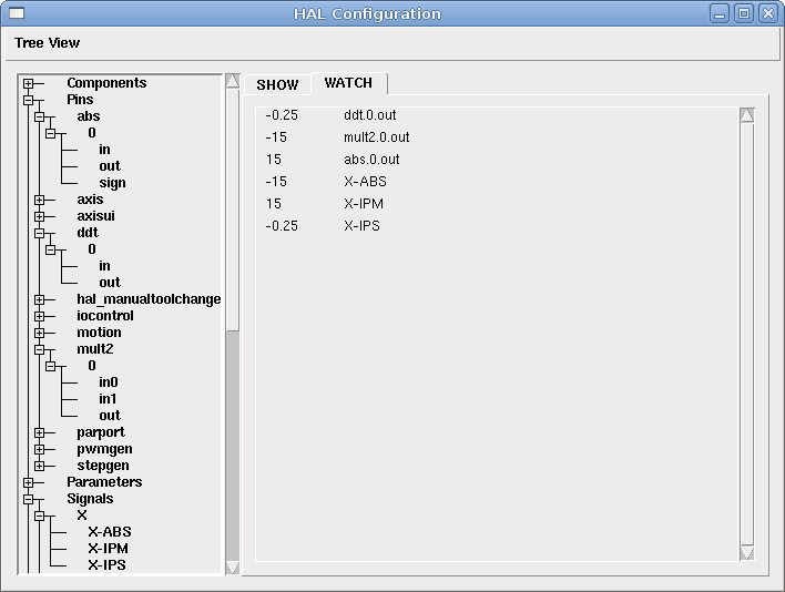
The first thing is to check your configuration to make sure you are not using any of the real time components all ready. You can do this by opening up the HAL Configuration window and look for the components in the pin section. If you are then find the .hal file that they are being loaded in and increase the counts and adjust the instance to the correct value. Add the following to your custom.hal file.
Load the realtime components.
loadrt ddt count=1
loadrt mult2 count =1
loadrt abs count=1
Add the functions to a thread so it will get updated.
addf ddt.0 servo-thread
addf mult2.0 servo-thread
addf abs.0 servo-thread
Make the connections.
setp mult2.in1 60
net xpos-cmd ddt.0.in
net X-IPS mult2.0.in0 <= ddt.0.out
net X-ABS abs.0.in <= mult2.0.out
net X-IPM abs.0.out
In this last section we are setting the mult2.0.in1 to 60 to convert the inch per second to inch per minute that we get from the ddt.0.out.
The xpos-cmd sends the comanded position to the ddt.0.in. The ddt computes the derivative of the change of the input.
The ddt2.0.out is multiplyed by 60 to give IPM.
The mult2.0.out is sent to the abs to get the absolute value.
The following figure shows the result when the X axis is moving at 15 IPM in the minus direction. Notice that we can get the absolute value from either the abs.0.out pin or the X-IPM signal.
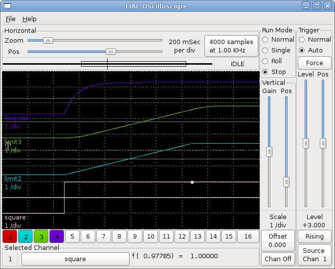
This example shows how the HAL components "lowpass", "limit2" or "limit3" can be used to limit how fast a signal changes.
In this example we have a servo motor driving a lathe spindle. If we just used the commanded spindle speeds on the servo it will try and go from present speed to commanded speed as fast as it can. This could cause a problem or damage the drive. To slow the rate of change we can send the motion.spindle-speed-out through a limiter before the PID, so that the PID command value varies slowly.
Three built-in components that limit a signal are:
To find more information on these HAL components check the man pages.
Place the following in a text file called softstart.hal. If you're not familiar with Linux place the file in your home directory.
##############################
loadrt threads period1=1000000 name1=thread
loadrt siggen
loadrt lowpass
loadrt limit2
loadrt limit3
net square siggen.0.square => lowpass.0.in limit2.0.in limit3.0.in
net lowpass <= lowpass.0.out
net limit2 <= limit2.0.out
net limit3 <= limit3.0.out
setp siggen.0.frequency .1
setp lowpass.0.gain .01
setp limit2.0.maxv 2
setp limit3.0.maxv 2
setp limit3.0.maxa 10
addf siggen.0.update thread
addf lowpass.0 thread
addf limit2.0 thread
addf limit3.0 thread
start
loadusr halscope
##############################
Open a terminal window and run the file with the following command.
halrun -I softstart.hal
When the HAL Oscilloscope first starts up click "OK" to accept the default thread.
Next you have to add the signals to the channels. Click on channel 1 then select "square" from the Signals tab. Repeat for channels 2-4 and add lowpass, limit2, and limit3.
Next to set up a trigger signal click on the Source None button and select square. The button will change to Source Chan 1.
Next click on Single in the Run Mode radio buttons box. This will start a run and when it finishes you will see your traces.
To separate the signals so you can see them better click on a channel then use the Pos slider in the Vertical box to set the positions.
To see the effect of changing the set point values of any of the components you can change them in the terminal window. To see what different gain settings do for lowpass just type the following in the terminal window and try different settings.
setp lowpass.0.gain .01
After changing a setting run the oscilloscope again to see the change.
When you're finished type "exit" in the terminal window to shut down halrun and close the halscope. Don't close the terminal window with halrun running as it might leave some things in memory that could prevent EMC from loading.
For more information on HalScope see the HAL manual.