 Figure: TkEMC Window
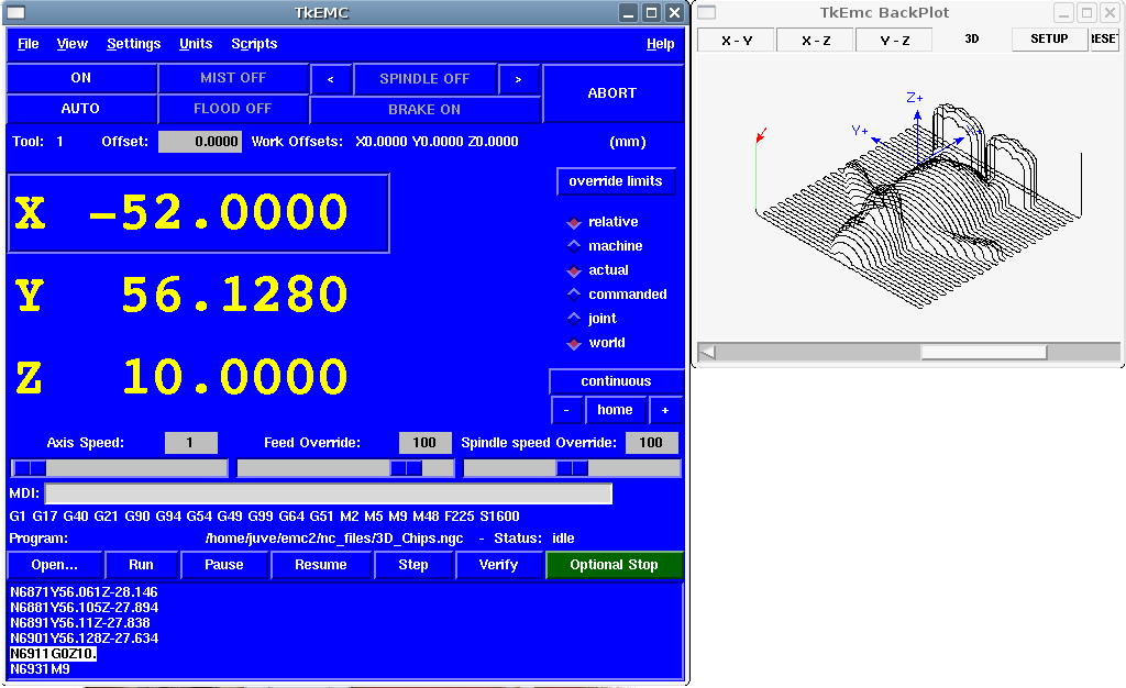
TkEMC is one of the most traditional graphical front-ends for EMC. It is written in Tcl and uses the Tk toolkit for the display. Being written in TCL makes it very portable (runs on a multitude of platforms). A separate backplot window can be displayed as shown in Figure([.]).
To select TkEMC as the front-end for EMC2, edit the .ini file. In the section [DISPLAY] change the DISPLAY line to read
DISPLAY = tkemc
Then, start EMC2 and select that ini file. The sample configuration sim/tkemc.ini is already configured to use TkEMC as its front-end.
When you start EMC2 with TkEMC, a window like the one in Figure [.] is shown.
The TkEMC window contains the following elements:
From left to right, the buttons are:
then on the second line:
The Offset display status bar displays the currently selected tool (selected with Txx M6), the tool length offset (if active), and the work offsets (set by right clicking the coordinates).
The main part of the display shows the current position of the tool. The colour of the position readout depends on the state of the axis. If the axis is unhomed the axis will be displayed in yellow letters. Once homed it will be displayed in green letters. If there is an error with the current axis TkEMC will use red letter to show that. (for example if an hardware limit switch is tripped).
To properly interpret these numbers, refer to the radio boxes on the right. If the position is “Machine”, then the displayed number is in the machine coordinate system. If it is “Relative”, then the displayed number is in the offset coordinate system. Further down the choices can be “actual” or “commanded”. Actual refers to the feedback coming from encoders (if you have a servo machine), and the “commanded” refers to the position command send out to the motors. These values can differ for several reasons: Following error, deadband, encoder resolution, or step size. For instance, if you command a movement to X 0.0033 on your mill, but one step of your stepper motor is 0.00125, then the “Commanded” position will be 0.0033 but the “Actual” position will be 0.0025 (2 steps) or 0.00375 (3 steps).
Another set of radio buttons allows you to choose between “joint” and “world” view. These make little sense on a normal type of machine (e.g. trivial kinematics), but helps on machines with non-trivial kinematics like robots or stewart platforms. (you can read more about kinematics in the Integrators Handbook).
When the machine moves, it leaves a trail called the backplot. You can start the backplot window by selecting View->Backplot.
The buttons in the lower part of TkEMC (seen in Figure [.]) are used to control the execution of a program: “Open” to load a program, “Verify” to check it for errors, “Run” to start the actual cutting, “Pause” to stop it while running, “Resume” to resume an already paused program, “Step” to advance one line in the program and “Optional Stop” to toggle the optional stop switch (if the button is green the program execution will be stopped on any M1 encountered).
When the program is running, the line currently being executed is highlighted in white. The text display will automatically scroll to show the current line.
TkEMC allows you to manually move the machine. This action is known as “jogging”. First, select the axis to be moved by clicking it. Then, click and hold the “+” or “-” button depending on the desired direction of motion. The first four axes can also be moved by the arrow keys (X and Y), PAGE UP and PAGE DOWN keys (Z) and the [ and ] keys (A).
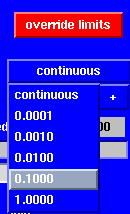
If “Continuous” is selected, the motion will continue as long as the button or key is pressed. If another value is selected, the machine will move exactly the displayed distance each time the button is clicked or the key is pressed. The available values are:
1.0000 0.1000 0.0100 0.0010 0.0001
By pressing “Home” or the HOME key, the selected axis will be homed. Depending on your configuration, this may just set the axis value to be the absolute position 0.0, or it may make the machine move to a specific home location through use of “home switches”. See the Integrators Manual for more information on homing.
By pressing “Override Limits”, the machine will temporarily be permitted to jog outside the limits defined in the .ini file. (Note: if “Override Limits” is active the button will be displayed using a red colour).
The button on the first row select the direction for the spindle to rotate: Counterclockwise, Stopped, Clockwise. The buttons next to it allow the user to increase or decrease the rotation speed. The button on the second row allows the spindle brake to be engaged or released. Depending on your machine configuration, not all the items in this group may have an effect.
The two buttons allow the “Mist” and “Flood” coolants to be turned on and off. Depending on your machine configuration, not all the items in this group may appear.
Manual Data Input (also called MDI), allows G-code programs to be entered manually, one line at a time. When the machine is not turned on, and not set to MDI mode, the code entry controls are unavailable.
This allows you to enter a g-code command to be executed. Execute the command by pressing Enter.
This shows the “modal codes” that are active in the interpreter. For instance, “G54” indicates that the “G54 offset” is applied to all coordinates that are entered.
By moving this slider, the speed of jogs can be modified. The numbers above refer to axis units / second. The text box with the number is clickable. Once clicked a popup window will appear, allowing for a number to be entered.
By moving this slider, the programmed feed rate can be modified. For instance, if a program requests F60 and the slider is set to 120%, then the resulting feed rate will be 72. The text box with the number is clickable. Once clicked a popup window will appear, allowing for a number to be entered.
The spindle speed override slider works exactly like the feed override slider, but it controls to the spindle speed. If a program requested S500 (spindle speed 500 RPM), and the slider is set to 80%, then the resulting spindle speed will be 400 RPM. This slider has a minimum and maximum value defined in the ini file. If those are missing the slider is stuck at 100%. The text box with the number is clickable. Once clicked a popup window will appear, allowing for a number to be entered.
Almost all actions in TkEMC can be accomplished with the keyboard. Many of the shortcuts are unavailable when in MDI mode.
The most frequently used keyboard shortcuts are shown in Table [.].
| Keystroke | Action Taken |
| F1 | Toggle Emergency Stop |
| F2 | Turn machine on/off |
| `, 1 .. 9, 0 | Set feed override from 0% to 100% |
| X, ` | Activate first axis |
| Y, 1 | Activate second axis |
| Z, 2 | Activate third axis |
| A, 3 | Activate fourth axis |
| Home | Send active axis Home |
| Left, Right | Jog first axis |
| Up, Down | Jog second axis |
| Pg Up, Pg Dn | Jog third axis |
| [, ] | Jog fourth axis |
| ESC | Stop execution |
1 for some of these actions it might be needed to change the mode emc2 currently is in. back