Figure: Step Pulse Generator Block Diagram (position mode)
Most components have unix-style manual pages. To view manual pages for real-time components, type “man 9 componentname” at the terminal prompt.
This document focuses on more complicated components which have figures which are hard to reproduce in the manual page format.
This component provides software based generation of step pulses in response to position or velocity commands. In position mode, it has a built in pre-tuned position loop, so PID tuning is not required. In velocity mode, it drives a motor at the commanded speed, while obeying velocity and acceleration limits. It is a realtime component only, and depending on CPU speed, etc, is capable of maximum step rates of 10kHz to perhaps 50kHz. Figure [.] shows three block diagrams, each is a single step pulse generator. The first diagram is for step type '0', (step and direction). The second is for step type '1' (up/down, or pseudo-PWM), and the third is for step types 2 through 14 (various stepping patterns). The first two diagrams show position mode control, and the third one shows velocity mode. Control mode and step type are set independently, and any combination can be selected.
emc2$ halcmd loadrt stepgen step_type=<type-array> [ctrl_type=<ctrl_array>]
<type-array> is a series of comma separated decimal integers. Each number causes a single step pulse generator to be loaded, the value of the number determines the stepping type. <ctrl_array> is a comma separated series of “p” or “v” characters, to specify position or velocity mode. ctrl_type is optional, if ommitted, all of the step generators will be position mode. For example:
emc2# halcmd loadrt stepgen.o step_type=0,0,2 ctrl_type=p,p,v
will install three step generators. The first two use step type '0' (step and direction) and run in position mode. The last one uses step type '2' (quadrature) and runs in velocity mode. The default value for <config-array> is “0,0,0” which will install three type '0' (step/dir) generators. The maximum number of step generators is 8 (as defined by MAX_CHAN in stepgen.c). Each generator is independent, but all are updated by the same function(s) at the same time. In the following descriptions, <chan> is the number of a specific generator. The first generator is number 0.
emc2$ halcmd unloadrt stepgen
Each step pulse generator will have only some of these pins, depending on the step type and control type selected.
In position mode, the values of maxvel and maxaccel are used by the internal position loop to avoid generating step pulse trains that the motor cannot follow. When set to values that are appropriate for the motor, even a large instantaneous change in commanded position will result in a smooth trapezoidal move to the new location. The algorithm works by measuring both position error and velocity error, and calculating an acceleration that attempts to reduce both to zero at the same time. For more details, including the contents of the “control equation” box, consult the code.
In velocity mode, maxvel is a simple limit that is applied to the commanded velocity, and maxaccel is used to ramp the actual frequency if the commanded velocity changes abruptly. As in position mode, proper values for these parameters ensure that the motor can follow the generated pulse train.
The step generator supports 15 different “step types”. Step type 0 is the most familiar, standard step and direction. When configured for step type 0, there are four extra parameters that determine the exact timing of the step and direction signals. See figure [.] for the meaning of these parameters. The parameters are in nanoseconds, but will be rounded up to an integer multiple of the thread period for the threaed that calls make_pulses(). For example, if make_pulses() is called every 16uS, and steplen is 20000, then the step pulses will be 2 x 16 = 32uS long. The default value for all four of the parameters is 1nS, but the automatic rounding takes effect the first time the code runs. Since one step requires steplen nS high and stepspace nS low, the maximum frequency is 1,000,000,000 divided by (steplen+stepspace). If maxfreq is set higher than that limit, it will be lowered automatically. If maxfreq is zero, it will remain zero, but the output frequency will still be limited.
Step type 1 has two outputs, up and down. Pulses appear on one or the other, depending on the direction of travel. Each pulse is steplen nS long, and the pulses are separated by at least stepspace nS. The maximum frequency is the same as for step type 0. If maxfreq is set higher than the limit it will be lowered. If maxfreq is zero, it will remain zero but the output frequency will still be limited.
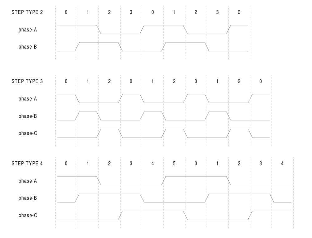
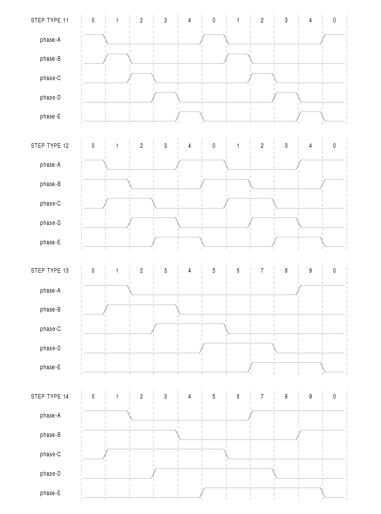
Step types 2 through 14 are state based, and have from two to five outputs. On each step, a state counter is incremented or decremented. Figures [.], [.], and [.] show the output patterns as a function of the state counter. The maximum frequency is 1,000,000,000 divided by steplen, and as in the other modes, maxfreq will be lowered if it is above the limit.
The component exports three functions. Each function acts on all of the step pulse generators - running different generators in different threads is not supported.
The high speed function stepgen.make-pulses should be run in a very fast thread, from 10 to 50uS depending on the capabilities of the computer. That thread's period determines the maximum step frequency, since steplen, stepspace, dirsetup, dirhold, and dirdelay are all rounded up to a integer multiple of the thread periond in nanoseconds. The other two functions can be called at a much lower rate.
This component provides software based generation of PWM (Pulse Width Modulation) and PDM (Pulse Density Modulation) waveforms. It is a realtime component only, and depending on CPU speed, etc, is capable of PWM frequencies from a few hundred Hertz at pretty good resolution, to perhaps 10KHz with limited resolution.
emc2$ halcmd loadrt pwmgen output_type=<config-array>
<config-array> is a series of comma separated decimal integers. Each number causes a single PWM generator to be loaded, the value of the number determines the output type. For example:
emc2$ halcmd loadrt pwmgen step_type=0,1,2
will install three PWM generators. The first one will use output type '0' (PWM only), the next uses output type 1 (PWM and direction) and the last one uses output type 2 (UP and DOWN). There is no default value, if <config-array> is not specified, no PWM generators will be installed. The maximum number of frequency generators is 8 (as defined by MAX_CHAN in pwmgen.c). Each generator is independent, but all are updated by the same function(s) at the same time. In the following descriptions, <chan> is the number of a specific generator. The first generator is number 0.
emc2$ halcmd unloadrt pwmgen
Each PWM generator will have the following pins:
Each PWM generator will also have some of these pins, depending on the output type selected:
The PWM generator supports three different “output types”. Type 0 has a single output pin. Only positive commands are accepted, negative values are treated as zero (and will be affected by min-dc if it is non-zero). Type 1 has two output pins, one for the PWM/PDM signal and one to indicate direction. The duty cycle on the PWM pin is based on the absolute value of the command, so negative values are acceptable. The direction pin is false for positive commands, and true for negative commands. Finally, type 2 also has two outputs, called up and down. For positive commands, the PWM signal appears on the up output, and the down output remains false. For negative commands, the PWM signal appears on the down output, and the up output remains false. Output type 2 is suitable for driving most H-bridges.
The component exports two functions. Each function acts on all of the PWM generators - running different generators in different threads is not supported.
The high speed function pwmgen.make-pulses should be run in a very fast thread, from 10 to 50uS depending on the capabilities of the computer. That thread's period determines the maximum PWM carrier frequency, as well as the resolution of the PWM or PDM signals. The other function can be called at a much lower rate.
This component provides software based counting of signals from quadrature encoders. It is a realtime component only, and depending on CPU speed, etc, is capable of maximum count rates of 10kHz to perhaps 50kHz. Figure [.] is a block diagram of one channel of encoder counter.
emc2$ halcmd loadrt encoder [num_chan=<counters>]
<counters> is the number of encoder counters that you want to install. If numchan is not specified, three counters will be installed. The maximum number of counters is 8 (as defined by MAX_CHAN in encoder.c). Each counter is independent, but all are updated by the same function(s) at the same time. In the following descriptions, <chan> is the number of a specific counter. The first counter is number 0.
emc2$ halcmd unloadrt encoder
The component exports two functions. Each function acts on all of the encoder counters - running different counters in different threads is not supported.
This component provides Proportional/Integeral/Derivative control loops. It is a realtime component only. For simplicity, this discussion assumes that we are talking about position loops, however this component can be used to implement other feedback loops such as speed, torch height, temperature, etc. Figure [.] is a block diagram of a single PID loop.
emc2$ halcmd loadrt pid [num_chan=<loops>] [debug=1]
<loops> is the number of PID loops that you want to install. If numchan is not specified, one loop will be installed. The maximum number of loops is 16 (as defined by MAX_CHAN in pid.c). Each loop is completely independent. In the following descriptions, <loopnum> is the loop number of a specific loop. The first loop is number 0.
If debug=1 is specified, the component will export a few extra parameters that may be useful during debugging and tuning. By default, the extra parameters are not exported, to save shared memory space and avoid cluttering the parameter list.
emc2$ halcmd unloadrt pid
The three most important pins are
For a position loop, 'command' and 'feedback' are in position units. For a linear axis, this could be inches, mm, meters, or whatever is relevant. Likewise, for an angular axis, it could be degrees, radians, etc. The units of the 'output' pin represent the change needed to make the feedback match the command. As such, for a position loop 'Output' is a velocity, in inches/sec, mm/sec, degrees/sec, etc. Time units are always seconds, and the velocity units match the position units. If command and feedback are in meters, then output is in meters per second.
Each loop has two other pins which are used to monitor or control the general operation of the component.
The PID gains, limits, and other 'tunable' features of the loop are implemented as parameters.
All of the max ??? limits are implemented such that if the parameter value is zero, there is no limit.
If debug=1 was specified when the component was installed, four additional parameters will be exported:
The component exports one function for each PID loop. This function performs all the calculations needed for the loop. Since each loop has its own function, individual loops can be included in different threads and execute at different rates.
If you want to understand the exact algorithm used to compute the output of the PID loop, refer to figure [.], the comments at the beginning of emc2/src/hal/components/pid.c, and of course to the code itself. The loop calculations are in the C function calc_pid().
The simulated encoder is exactly that. It produces quadrature pulses with an index pulse, at a speed controlled by a HAL pin. Mostly useful for testing.
emc2$ halcmd loadrt sim-encoder num_chan=<number>
<number> is the number of encoders that you want to simulate. If not specified, one encoder will be installed. The maximum number is 8 (as defined by MAX_CHAN in sim_encoder.c).
emc2$ halcmd unloadrt sim-encoder
When .speed is positive, .phase-A leads .phase-B.
Note that pulses per revolution is not the same as counts per revolution. A pulse is a complete quadrature cycle. Most encoder counters will count four times during one complete cycle.
The component exports two functions. Each function affects all simulated encoders.
Debounce is a realtime component that can filter the glitches created by mechanical switch contacts. It may also be useful in other applications where short pulses are to be rejected.
emc2$ halcmd loadrt debounce cfg=”<config-string>”
<config-string> is a series of space separated decimal integers. Each number installs a group of identical debounce filters, the number determines how many filters are in the group. For example:
emc2$ halcmd loadrt debounce cfg=”1 4 2”
will install three groups of filters. Group 0 contains one filter, group 1 contains four, and group 2 contains two filters. The default value for <config-string> is “1” which will install a single group containing a single filter. The maximum number of groups 8 (as defined by MAX_GROUPS in debounce.c). The maximum number of filters in a group is limited only by shared memory space. Each group is completely independent. All filters in a single group are identical, and they are all updated by the same function at the same time. In the following descriptions, <G> is the group number and <F> is the filter number within the group. The first filter is group 0, filter 0.
emc2$ halcmd unloadrt debounce
Each individual filter has two pins.
Each group of filters has one parameter2.
The filter delay is in units of thread periods. The minimum delay is zero. The output of a zero delay filter exactly follows its input - it doesn't filter anything. As delay increases, longer and longer glitches are rejected. If delay is 4, all glitches less than or equal to four thread periods will be rejected.
Each group of filters has one function, which updates all the filters in that group “simultaneously”. Different groups of filters can be updated from different threads at different periods.
Siggen is a realtime component that generates square, triangle, and sine waves. It is primarily used for testing.
emc2$ halcmd loadrt siggen [num_chan=<chans>]
<chans> is the number of signal generators that you want to install. If numchan is not specified, one signal generator will be installed. The maximum number of generators is 16 (as defined by MAX_CHAN in siggen.c). Each generator is completely independent. In the following descriptions, <chan> is the number of a specific signal generator (the numbers start at 0).
emc2$ halcmd unloadrt siggen
Each generator has five output pins.
All five outputs have the same frequency, amplitude, and offset.
In addition to the output pins, there are three control pins:
For example, if siggen.0.amplitude is 1.0 and siggen.0.offset is 0.0, the outputs will swing from -1.0 to +1.0. If siggen.0.amplitude is 2.5 and siggen.0.offset is 10.0, then the outputs will swing from 7.5 to 12.5.
None. 3
1 FF2 is not currently implemented, but it will be added. Consider this note a “FIXME” for the code back
2 Each individual filter also has an internal state variable. There is a compile time switch that can export that variable as a parameter. This is intended for testing, and simply wastes shared memory under normal circumstances. back
3 Prior to version 2.1, frequency, amplitude, and offset were parameters. They were changed to pins to allow control by other components. back