×
Forum Header
Light Machines Company Mill
22 Sep 2010 20:08 #4287
by shaworth
Replied by shaworth on topic Re:Light Machines Company Mill
rexhunt wrote:
You do have that controller (The only LMC controller I'm aware of), right?
Shannon
I have no idea. However the cable is only designed to work with the controller photographed on the bottom of this page: build.spaceopera.org/site/reverseenginee...ontroller/index.htmlIs there a difference between the Intelletek and the Light Machines Corporation mils?
You do have that controller (The only LMC controller I'm aware of), right?
Shannon
Please Log in or Create an account to join the conversation.
12 Oct 2010 00:45 #4631
by rexhunt
Replied by rexhunt on topic Re:Light Machines Company Mill
sorry i was taking a break during the school holidays
yep that is the controler box that I am using... that could have been quite embarassing
printed on the big PCB inside it should be the revision... I am thinking that I may have a different one or the jumpers inside may be configured differently
yep that is the controler box that I am using... that could have been quite embarassing
printed on the big PCB inside it should be the revision... I am thinking that I may have a different one or the jumpers inside may be configured differently
Please Log in or Create an account to join the conversation.
14 Oct 2010 00:03 #4665
by rexhunt
Replied by rexhunt on topic Re:Light Machines Company Mill
on a closer inspection, my controller box has not got a wire guard over the fan... not sure if that means anything though?
hopefully soon i will have a faster machine completely set up to run the software... does it absolutely have to have the 300 odd megabytes of ram?
hopefully soon i will have a faster machine completely set up to run the software... does it absolutely have to have the 300 odd megabytes of ram?
Please Log in or Create an account to join the conversation.
12 Nov 2010 23:18 #5282
by shaworth
Replied by shaworth on topic Re:Light Machines Company Mill
So, did you ever get anywhere with this?
Shannon
Shannon
Please Log in or Create an account to join the conversation.
13 Nov 2010 09:42 #5286
by rexhunt
Replied by rexhunt on topic Re:Light Machines Company Mill
sorry I didnt reply sooner, I had exams...
the control box is a different version which means that I am just going to try it with the old software. So untill I can get the windows based one working and seeing the spectracam thing then I will have to install the dos version we have and dos or win 95.
thanks for all your help all the same,
Rex
Please Log in or Create an account to join the conversation.
- Contract_Pilot
-

- Offline
- Senior Member
-

Less
More
- Posts: 79
- Thank you received: 11
15 Sep 2015 06:00 - 15 Sep 2015 06:26 #62600
by Contract_Pilot
Replied by Contract_Pilot on topic Light Machines Company Mill
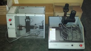
Recently acquired 2 machines and a controller box. Installed LCNC on a box last week for my other machine build but since I got these and they are 80% ready to run what a way to learn LCNC!
Anyone have an archive of the cable plans and Linux cnc file. I did find this is there anything else needed but to just rewire a DB25 Cable? And are these pin-outs correct for both lathe and mill's? The lathe has a encoder on the spindle i do not see it on the pin outs.
Parallel port (Male) Controller box cable (Female) Notes
1 22 Enables the spindle
2 6 X Dir
3 21 X Step
4 18 Y Dir
5 20 Y Step
6 5 Z Dir
7 19 Z Step
8 4 Spindle on/off
13 23 ESTOP Warning: May or may not work, if connecting this causes EMC to stop (thinking the button has been pressed at random times), disable it in the stepconf. Placing a 10uf (and possibly much smaller) capacitor in parallel with this signal and grounding it acts as a filter. Problems with this line were resolved using this technique.
14 17 Mill Amp on/off
25 7 GND
Machines.
Last edit: 15 Sep 2015 06:26 by Contract_Pilot.
Please Log in or Create an account to join the conversation.
- Contract_Pilot
-
- Offline
- Senior Member
-
Less
More
- Posts: 79
- Thank you received: 11
17 Sep 2015 06:06 #62661
by Contract_Pilot
Replied by Contract_Pilot on topic Light Machines Company Mill
Wired up the cable figured out what Limit Switches, Spindle, E-stop works but no movement on steppers. I am going to say maybe it is the voltage on the parallel port. Thinking maybe a
C26 - OUTPUT BUFFER BOARD
may work? Any Ideas?
Please Log in or Create an account to join the conversation.

17 Sep 2015 06:15 #62663
by andypugh
Wire the p-port to sink current rather than source, and invert the step signals in stepconf.
Replied by andypugh on topic Light Machines Company Mill
Wired up the cable figured out what Limit Switches, Spindle, E-stop works but no movement on steppers. I am going to say maybe it is the voltage on the parallel port. Thinking maybe a C26 - OUTPUT BUFFER BOARD may work? Any Ideas?
Wire the p-port to sink current rather than source, and invert the step signals in stepconf.
Please Log in or Create an account to join the conversation.
- Contract_Pilot
-
- Offline
- Senior Member
-
Less
More
- Posts: 79
- Thank you received: 11
17 Sep 2015 07:02 - 17 Sep 2015 07:19 #62668
by Contract_Pilot
Replied by Contract_Pilot on topic Light Machines Company Mill
OK, Sink then Source has me lost??? Please explain! I understand invert the step signals!
How I have it Now on the light machines.
PC EPP - Controller
1 -> 22 Spindle CW (Working Turns On Spindle)
2 -> 6 X DIR
3 -> 21 X Step
4 -> 18 Y Dir
5 -> 20 Y Step
6 -> 5 Z Dir
7 -> 19 Z Step
9 -> 4 Spindle on/off (Working)
10 -> 23 E-stop (Working)
12 -> 13 Home (Invert)
13 -> 24 limit (Invert working)
8 -> 17 Amp Enable
15 -> 11 Cover Motor Switch (Working)
18 -> 7 Ground
20 -> 10 UF Cap to 23 for e-Stop to work (Working)
Last edit: 17 Sep 2015 07:19 by Contract_Pilot.
Please Log in or Create an account to join the conversation.
17 Sep 2015 07:17 #62669
by andypugh
Replied by andypugh on topic Light Machines Company Mill
My stepper drivers have opto-isolator inputs.
To make them work with a parallel port I had to connect the high-side of the opto to +5V and the low side to the parallel port.
So, P-port @5V = no current flow. P-port at zero volts current flow through the LED of the opto from +5V, through the Led + resistor (in the drive) and then onto the parport to GND.
Some parports can only source 3mA, but most can sink 15mA.
Please Log in or Create an account to join the conversation.
Time to create page: 0.092 seconds