1. Stepper Motor Operation
Stepper motors operate by sequentially energising and de-energising several coils surrounding the rotor in such a way that the shaft is magnetically forced to rotate around in discrete steps. Steps of 0.9 - 1.8 degrees are quite common, giving 400 - 200 steps per full revolution of the shaft.
As in real life, nothing can change from one state to another with absolutely no time delay. In the case of the stepper motor, the current passing through each coil, and thus the magnetic field that pulls the rotor around to each step of rotation takes some time to take effect. This is due to the coil having inductance (expressed in Henries, abbreviated to the letter H) which has a natural tendency to resist the flow of a rapidly changing current. More coil inductance results in a slower rate of current change and thus a slower rate of magnetic field expansion and contraction.
The maximum torque that the stepper motor can achieve is when the motor is stationary with one winding energised. This figure may be quoted on a stepper motor datasheet as the holding torque. As the rate at which each coil is energised and de-energised increases to induce rotation in the shaft, the time that each coil can exert its full magnetic attraction on the rotor reduces, thereby reducing the overall torque. This relationship between speed and torque is largely inversely proportional.
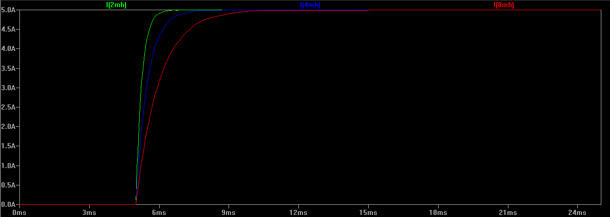
In the below example, the charging time for three coils is shown when the applied voltage is stepped from 0 V to 40 V. While all three coils can easily reach the full current limit of 5 amps (A), the time taken varies for each coil. The 4 milli-Henry (mH) coil (blue trace) takes twice as long to reach full current than the 2 mH coil (green trace), and the 8 mH (red trace) coil takes twice as long again:
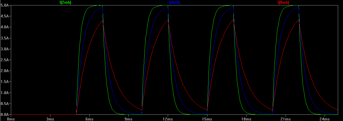
If the rate at which step changes are applied to the coils is significantly shorter than the rise time, it’s easy to see that the winding has less time to attain full magnetic attraction on the rotor, and thus maximum torque is curtailed. In the below example the 2 mH coil can achieve the full 5 A limit before the step voltage is removed, but the 4 mH and 8 mH coils cannot:
The accepted way of improving motor speed while maintaining torque is to increase the speed at which the magnetic field of the motor coils can expand and collapse. The easiest way to accomplish this is to increase the supply voltage to force the current in each winding to rise and fall much more rapidly. A quicker magnetising time equates to faster step rates while improving torque at higher speeds, both of which are obviously desirable in a CNC system.
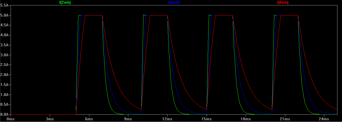
Using the same example as above, but increasing the step voltage to 80 V it can be seen that all three coils can now reach the 5 A maximum quite easily:
However, careful management of a higher drive voltage is required, as a higher voltage will increase current flowing in each coil with a corresponding increase in temperature of the winding. Excessive temperature rise in the winding will lead to eventual overheating and failure of the motor.
In most stepper-based CNC systems the voltage of the supply feeding the stepper driver is several orders of magnitude greater than the voltage of the motor itself. A typical NEMA23 stepper motor may have a rating of only a handful of volts, yet the power supply and driver could be operating at 48 VDC or more.
Nearly all modern stepper motor drivers on the market today are constant-current types. That is, the current being applied to each winding is fixed irrespective of how much voltage is being applied. Most drivers accomplish this by monitoring the current being drawn through the motor windings and rapidly switching the outputs on and off at a very high frequency to maintain this current. Depending on the drivers being used, it may even be possible to hear this high frequency whistling in the motors themselves when stationary. Because the voltage is rapidly switched on and off to maintain the winding current at an approximate fixed value, these types of drivers are also known as chopper drive.
2. Selecting a Stepper Power Supply
While a higher voltage is directly related to more speed and torque, obviously there comes a limit where increasing supply voltage is no longer beneficial. The first limitation to the maximum power supply voltage is likely to be what the stepper driver itself is capable of withstanding. This value should be provided in the datasheet for the stepper driver, and exceeding this voltage will result in the destruction of the driver. Ideally the power supply voltage should be chosen with a degree of headroom that falls under this maximum voltage limit of around 10%. If, for example a stepper driver has a Vmax rating of 80 VDC, the maximum power supply voltage should be limited to 72 VDC.
As mentioned above, excessive motor supply voltage also leads to excessive heat rise in the motor windings, which can lead to eventual failure of the motor through overheating. A commonly used equation for providing a guideline in determining the maximum voltage to prevent excessive heat rise is to take the square-root of the winding inductance quoted in the motor datasheet (expressed in mill-Henries) and multiply by 32. For example, choosing a stepper with a coil inductance of 4 mH will result in a maximum power supply voltage of 32 x SQRT (4) = 64 VDC.
Many stepper motor datasheets will also provide speed/torque curves, often plotted using different supply voltages. By studying the graphs it may be determined that increasing the supply voltage by a factor of two will not result in a corresponding improvement in speed/torque by the same degree. If there is little to be gained in running a stepper motor at 64 VDC, this may help in narrowing down the proposed power supply to 32 VDC which will also help minimise excessive heat rise in the motor windings.
The other factor to consider is the current rating of the power supply. This is based from the motor’s winding current ratings and whether the motor windings are wired in series or parallel, both of which should be listed in the motor’s datasheet. A good rule of thumb is to size the power supply current rating at 2/3 of the rated phase current of the stepper motor if the windings are in parallel, or 1/3 of the rated current if wired in series. Thus, for a stepper motor rated at 4 A wired in parallel, the power supply needs to have a current rating of at least 2.7 A, or 1.3 A if wired in series. The total current rating of the complete system is then the sum of all stepper motors' current requirements.
3. Resonance
Motor resonance occurs when the rate at which the steps are applied to the windings matches the natural frequency of the motor itself. Applying steps for a prolonged period of time at this rate results in the torque dropping dramatically, and the motor may stall or even rotate in random directions. Some stepper motor datasheets provide plots of the torque/speed relationship and show a dip in the graph where resonance is likely to occur. It should be noted that this resonant peak provided in the datasheet is only for the motor itself - as soon as the motor is coupled to other components (i.e., installed in a CNC system) the resonant frequency may be altered, or even multiple new resonances introduced.
Several methods exist to help control the effects of resonance, all with varying degrees of complexity, effectiveness and side effects:
-
Microstepping can help reduce resonance by using smaller step changes in current between each step. These smaller step changes cause less ringing in the motor and windings and thus cause less excitation at the point of resonance.
-
Ensuring the motor is never operated at a particular frequency for a sustained period is a very basic method of reducing resonance, always accelerating or decelerating through the resonant peak.
-
Increasing inertial load will damp unwanted resonances at the expense of some torque and potentially some accuracy. Elastomeric motor mounts, shaft couplings or bearing mounts can be employed.
-
More advanced stepper motor drives may have the ability to switch between stepping modes such that the resonant peak is managed at certain rates of operation. Other systems exist to place electrical load on the windings, which has a similar effect to mechanical damping, above.
4. Microstepping
A stepper motor operating with each winding being fully energised in a sequential fashion is operating in full-step mode. That is, the maximum rotation resolution possible for that motor is the same as the number of whole steps that motor is manufactured to perform at (e.g., 200 steps per revolution for a 1.8 degree/step motor). As each winding is energised the rotor clocks around fully from one detent to the next.
Additional rotational resolution from a stepper motor can be obtained by performing microstepping, whereby the current being driven into each winding can essentially be ramped in discrete intermediate steps. This then causes the rotor to gradually straddle across each rotational detent rather than making the full jump from one step to the next.
Microstepping is commonly performed in multiples of 2 (4x, 8x, 16x, 32x etc). For example, a drive set to 4x microstepping will divide each step into four discrete current levels in the motor windings, thus affording an improvement in rotational resolution by a factor of four. This obviously means that for a typical step/direction control interface there will need to be four times as many step pulses generated to make the motor move the same amount had it been operating in full-step mode. To make the motor rotate at the same speed the rate at which pulses need to be applied to the drive also needs to be four times as fast.
At low rotational speeds, microstepping actually results in slightly higher torque than when full stepping. This is due to the smaller changes in current between intermediate steps resulting in less energy being wasted exciting natural resonances in the motor. As RPM increases however, torque tends to fall off at a similar rate as full stepping.
However, continuing to increase the degree of microstepping will eventually lead to some real-life limitations. Step pulse generation, particularly when using the parallel port, is limited in frequency. This will inevitably limit the maximum speed at which the drive can be commanded to step at. With high degrees of microstepping this will result in unacceptably slow RPM of the motor.
Excessively-high rates of microstepping have no real benefit if the resultant accuracy is too small to be mechanically useful. A 1.8 degree per step motor running at 16x microstepping is theoretically capable of 0.1125 degrees per step. Coupled with a 20 TPI leadscrew this should result in a positional resolution of 0.000016” or 0.0004 mm. In reality it is incredibly difficult to achieve such fine degrees of control. All components in the CNC system will contain tolerances and countering forces (backlash in leadscrews, flex in gantries, runout in the spindle and cutting tool, static friction in the stepper motor itself, stepper detent error , etc.) that will render such small amounts of resolution completely meaningless. In practice, microstepping at rates in excess of 4x or 8x on a CNC machine fitted with leadscrews serves little purpose. In some cases it may even be more beneficial to run at lower degrees of microstepping or even full steps, and operate the stepper motor through a gear reduction to obtain the necessary resolution and torque gains.
5. Open and Closed Loop
In the simplest CNC systems employing stepper motors, the host computer and/or stepper driver receives no feedback from the motor that it has achieved the desired outcome when commanded to begin stepping. The assumption by the software, driver and end user is that the motor operated correctly and the axis has moved to the expected new position. A system operating in this fashion is said to be running in open loop, where the device at the end of the signal chain (the stepper motor) does not provide any indication to the device at the start of the chain (the computer) that the target was reached.
A further enhancement to the basic stepper motor is to run the system in a closed loop. This is achieved by equipping the stepper motor with a rotary encoder whose positional signal is returned back to a device higher up in the signal chain. In this way the motors' actual position can be compared to the expected position at all times, and the drive parameters adjusted in real time to ensure that the motor does not fall behind. This enables closed loop stepper systems to be able to achieve better speed and torque performance than open loop systems, due to the system constantly compensating for any deviation to the stepper’s performance under varying loads.
Basic systems operating in this fashion may only close the loop between the motor and the driver, leaving the software on the host computer out of the loop. The software issues step/direction pulses to the downstream driver as it would normally when running in open loop. In these situations the drivers usually include an alarm output which signals the software to halt when the load placed on the stepper becomes too great for the driver to compensate without losing steps.
More advanced implementations of closed loop operation bring the encoder signal all the way back to the host computer, but require that a much higher hardware and software overhead be installed to manage the encoder feedback and calculation and delivery of drive compensation.