1. SPS / Kontaktplan Konzepte
ClassicLadder is a type of programming language originally implemented on industrial PLCs (it’s called Ladder Programming). It is based on the concept of relay contacts and coils, and can be used to construct logic checks and functions in a manner that is familiar to many systems integrators. Ladder consists of rungs that may have branches and resembles an electrical circuit. It is important to know how ladder programs are evaluated when running.
Entsprechend unserer Gewohnheiten würden wir erwarten, dass jede Zeile von links nach rechts ausgewertet wird, dann die nächste Zeile nach unten usw., aber in der Kontaktplanlogik funktioniert das nicht so. In der Kontaktplanlogik werden die Kontaktsprossen 3 Mal "gescannt", um den Zustand der Ausgänge zu ändern.
-
die Eingänge werden gelesen und aktualisiert
-
die Logik wird abgeleitet
-
die Ausgänge (engl. outputs) werden gesetzt
This can be confusing at first if the output of one line is read by the input of a another rung. There will be one scan before the second input becomes true after the output is set.
Another gotcha with ladder programming is the "Last One Wins" rule. If you have the same output in different locations of your ladder the state of the last one will be what the output is set to.
2. Sprachen
The most common language used when working with ClassicLadder is ladder. ClassicLadder also supports Sequential Function Chart (Grafcet).
3. Komponenten
ClassicLadder besteht aus zwei Komponenten.
-
The realtime module classicladder_rt
-
The non-realtime module (including a GUI) classicladder
3.1. Dateien
Typically ClassicLadder components are placed in the custom.hal file if your working from a StepConf generated configuration. These must not be placed in the custom_postgui.hal file or the Ladder Editor menu will be grayed out.
|
Anmerkung
|
Kontaktplan-Dateien (.clp) dürfen keine Leerzeichen im Namen enthalten. |
3.2. Echtzeit-Modul
Loading the ClassicLadder real time module (classicladder_rt) is possible from a HAL file, or directly using a halcmd instruction. The first line loads real time the ClassicLadder module. The second line adds the function classicladder.0.refresh to the servo thread. This line makes ClassicLadder update at the servo thread rate.
loadrt classicladder_rt
addf classicladder.0.refresh servo-thread
The speed of the thread that ClassicLadder is running in directly affects the responsiveness to inputs and outputs. If you can turn a switch on and off faster than ClassicLadder can notice it then you may need to speed up the thread. The fastest that ClassicLadder can update the rungs is one millisecond. You can put it in a faster thread but it will not update any faster. If you put it in a slower than one millisecond thread then ClassicLadder will update the rungs slower. The current scan time will be displayed on the section display, it is rounded to microseconds. If the scan time is longer than one millisecond you may want to shorten the ladder or put it in a slower thread.
3.3. Variablen
It is possible to configure the number of each type of ladder object while loading the ClassicLadder real time module. If you do not configure the number of ladder objects ClassicLadder will use the default values.
| Objektname | Variablenname | Standardwert |
|---|---|---|
Anzahl der Sprossen |
(numRungs) |
100 |
Anzahl der Bits |
(numBits) |
20 |
Anzahl der Wortvariablen |
(numWords) |
20 |
Anzahl der Timer |
(numTimers) |
10 |
Anzahl der Timer IEC |
(numTimersIec) |
10 |
Anzahl der Monostabilen |
(numMonostables) |
10 |
Anzahl der Zähler |
(numCounters) |
10 |
Anzahl der Bitpins der HAL-Eingänge |
(numPhysInputs) |
15 |
Anzahl der HAL-Ausgangsbit-Pins |
(numPhysOutputs) |
15 |
Anzahl der arithmetischen Ausdrücke |
(numArithmExpr) |
50 |
Anzahl der Abschnitte |
(numSections) |
10 |
Anzahl der Symbole |
(numSymbols) |
Auto |
Anzahl der S32-Eingänge |
(numS32in) |
10 |
Anzahl der S32-Ausgänge |
(numS32out) |
10 |
Anzahl der Float-Eingänge |
(numFloatIn) |
10 |
Anzahl der Float-Ausgänge |
(numFloatOut) |
10 |
Objekte von größtem Interesse sind numPhysInputs, numPhysOutputs, numS32in und numS32out.
Changing these numbers will change the number of HAL bit pins available. numPhysInputs and numPhysOutputs control how many HAL bit (on/off) pins are available. numS32in and numS32out control how many HAL signed integers (+- integer range) pins are available.
Zum Beispiel (Sie brauchen nicht alle, nur einige wenige zu ändern):
loadrt classicladder_rt numRungs=12 numBits=100 numWords=10
numTimers=10 numMonostables=10 numCounters=10 numPhysInputs=10
numPhysOutputs=10 numArithmExpr=100 numSections=4 numSymbols=200
numS32in=5 numS32out=5
Um die Standardanzahl von Objekten zu laden:
loadrt classicladder_rt
4. Loading the ClassicLadder non-realtime module
ClassicLadder HAL commands must executed before the GUI loads or the menu item Ladder Editor will not function. If you used the Stepper Config Wizard place any ClassicLadder HAL commands in the custom.hal file.
To load the non-realtime module:
loadusr classicladder
|
Anmerkung
|
Es kann nur eine .clp-Datei geladen werden. Wenn Sie Ihren Kontaktplan unterteilen müssen, dann verwenden Sie Abschnitte. |
Um eine Kontaktplan-Datei zu laden:
loadusr classicladder myladder.clp
ClassicLadder Lade-Optionen
-
--nogui' - (lädt ohne den Kontaktplan-Editor) wird normalerweise verwendet, wenn die Fehlersuche beendet ist.
-
--modbus_port=port - (lädt die Modbus-Portnummer)
-
--modmaster - (initialisiert den MODBUS-Master) sollte das Kontaktplanprogramm zur gleichen Zeit laden oder der TCP-Port ist Standard.
-
--modslave - (initialisiert MODBUS-Slave) nur TCP
Zur Verwendung von ClassicLadder mit HAL ohne EMC:
loadusr -w classicladder
Die Option -w weist HAL an, die HAL-Umgebung nicht zu schließen, bevor Classic Ladder beendet ist.
Wenn Sie zuerst ein Kontaktplanprogramm mit der Option --nogui laden und dann ClassicLadder erneut ohne Optionen laden, zeigt die GUI das zuletzt geladene Kontaktplanprogramm an.
In AXIS können Sie die GUI über Datei/Kontaktplan-Editor… laden.
5. ClassicLadder GUI
If you load ClassicLadder with the GUI it will display two windows: Section display, and section manager.
5.1. Sektions-Manager
Wenn Sie ClassicLadder zum ersten Mal starten, sehen Sie ein leeres Fenster des Abschnittsmanagers.
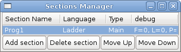
This window allows you to name, create or delete sections and choose what language that section uses. This is also how you name a subroutine for call coils.
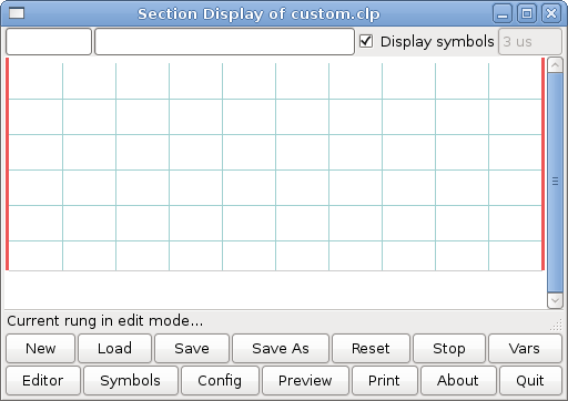
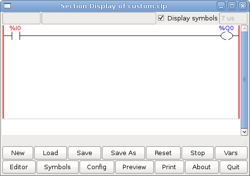
5.2. Abschnittsanzeige
Wenn Sie ClassicLadder zum ersten Mal starten, sehen Sie ein leeres Abschnittsanzeigefenster. Es wird eine leere Sprosse angezeigt.
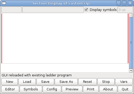
Die meisten Buttons sind selbsterklärend:
Die Button Vars dient zur Anzeige von Variablen. Sie können sie umschalten, um das eine, das andere, beide oder keines der Fenster anzuzeigen.
Der Button Config wird für Modbus verwendet und zeigt die maximale Anzahl von Kontaktplanelementen an, die mit dem Echtzeitmodul geladen wurden.
Der Button Symbole zeigt eine editierbare Liste von Symbolen für die Variablen an (Hinweis: Sie können die Eingänge, Ausgänge, Spulen usw. benennen).
The Quit button will shut down the non-realtime program, i.e. Modbus and the display. The realtime ladder program will still run in the background.
Über das Kontrollkästchen oben rechts können Sie auswählen, ob Variablennamen oder Symbolnamen angezeigt werden
You might notice that there is a line under the ladder program display that reads "Project failed to load…". That is the status bar that gives you info about elements of the ladder program that you click on in the display window. This status line will now display HAL signal names for variables %I, %Q and the first %W (in an equation). You might see some funny labels, such as (103) in the rungs. This is displayed (on purpose) because of an old bug- when erasing elements older versions sometimes didn’t erase the object with the right code. You might have noticed that the long horizontal connection button sometimes did not work in the older versions. This was because it looked for the free code but found something else. The number in the brackets is the unrecognized code. The ladder program will still work properly, to fix it erase the codes with the editor and save the program.
5.3. Die Variablenfenster
This are two variable windows: the Bit Status Window (boolean) and the Watch Window (signed integer). The Vars button is in the Section Display Window, toggle the Vars button to display one, the other, both, then none of the variable windows.
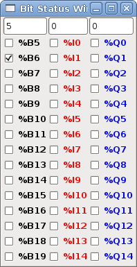
The Bit Status Window displays some of the boolean (on/off) variable data. Notice all variables start with the % sign. The %I variables represent HAL input bit pins. The %Q represents the relay coil and HAL output bit pins. The %B represents an internal relay coil or internal contact. The three edit areas at the top allow you to select what 15 variables will be displayed in each column. For instance, if the %B Variable column were 15 entries high, and you entered 5 at the top of the column, variables %B5 to %B19 would be displayed. The check boxes allow you to set and unset %B variables manually as long as the ladder program isn’t setting them as outputs. Any Bits that are set as outputs by the program when ClassicLadder is running can not be changed and will be displayed as checked if on and unchecked if off.
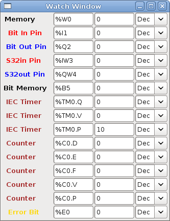
The Watch Window displays variable status. The edit box beside it is the number stored in the variable and the drop-down box beside that allow you to choose whether the number to be displayed in hex, decimal or binary. If there are symbol names defined in the symbols window for the word variables showing and the display symbols checkbox is checked in the section display window, symbol names will be displayed. To change the variable displayed, type the variable number, e.g. %W2 (if the display symbols check box is not checked) or type the symbol name (if the display symbols checkbox is checked) over an existing variable number/name and press the Enter Key.
5.4. Symbol-Fenster
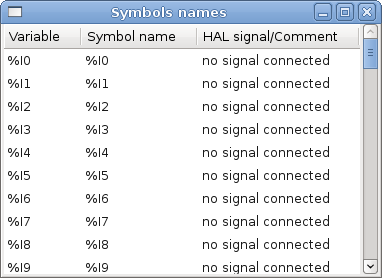
This is a list of symbol names to use instead of variable names to be displayed in the section window when the display symbols check box is checked. You add the variable name (remember the % symbol and capital letters), symbol name. If the variable can have a HAL signal connected to it (%I, %Q, and %W-if you have loaded s32 pin with the real time module) then the comment section will show the current HAL signal name or lack thereof. Symbol names should be kept short to display better. Keep in mind that you can display the longer HAL signal names of %I, %Q and %W variable by clicking on them in the section window. Between the two, one should be able to keep track of what the ladder program is connected to!
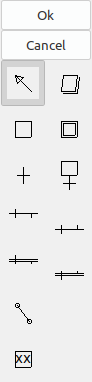
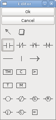
5.5. Das Editor-Fenster
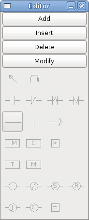
-
Hinzufügen (engl. add) - fügt eine Sprosse nach der ausgewählten Sprosse hinzu
-
Einfügen (engl. insert) - fügt eine Sprosse vor der ausgewählten Sprosse ein
-
Löschen (engl. delete) - löscht die ausgewählte Sprosse
-
Bearbeiten (engl. modify) - öffnet die ausgewählte Sprosse zur Bearbeitung
Beginnend mit dem Bild oben links:
-
Objektauswahl, Radiergummi
-
N.O. Input, N.C. Input, Rising Edge Input, Falling Edge Input
-
Horizontal Connection, Vertical Connection, Long Horizontal Connection
-
Timer IEC-Block, Zähler (engl. counter-)block, Vergleichsvariable
-
Alter Timer-Block, alter monostabiler Block (diese wurden durch den IEC-Timer ersetzt)
-
SPULEN (engl. coils) - N.O. Ausgang, N.C. Ausgang, den Ausgang setzen, Ausgang zurücksetzen
-
Jump Coil, Call Coil, Variable Zuweisung
Eine kurze Beschreibung der einzelnen Buttons:
-
Selector - ermöglicht es Ihnen, vorhandene Objekte auszuwählen und die Informationen zu ändern.
-
Radiergummi (engl. eraser) - löscht ein Objekt.
-
N.O. Contact - creates a normally open contact. It can be an external HAL-pin (%I) input contact, an internal-bit coil (%B) contact or a external coil (%Q) contact. The HAL-pin input contact is closed when the HAL-pin is true. The coil contacts are closed when the corresponding coil is active (%Q2 contact closes when %Q2 coil is active).
-
N.C. Kontakt - erstellt einen normalerweise geschlossenen Kontakt. Es ist das gleiche wie der N.O. Kontakt, außer dass der Kontakt offen ist, wenn der HAL-Pin wahr ist oder die Spule aktiv ist.
-
Rising Edge Contact - erzeugt einen Kontakt, der geschlossen wird, wenn der HAL-Pin von False auf True oder die Spule von nicht-aktiv auf aktiv wechselt.
-
Falling Edge Contact - erzeugt einen Kontakt, der geschlossen wird, wenn der HAL-Pin von true nach false oder die Spule von aktiv zu not wechselt.
-
Horizontale Verbindung - erzeugt eine horizontale Verbindung zu Objekten.
-
Vertikale Verbindung - erzeugt eine vertikale Verbindung zu horizontalen Linien.
-
Horizontal Running Connection - erstellt eine horizontale Verbindung zwischen zwei Objekten und ist eine schnelle Möglichkeit, Objekte zu verbinden, die mehr als einen Block voneinander entfernt sind.
-
IEC Timer - erstellt einen Timer und ersetzt den Timer.
-
Timer - erstellt ein Timer-Modul (veraltet, verwenden Sie stattdessen IEC-Timer).
-
Monostabil - erstellt ein monostabiles One-Shot-Modul
-
Counter - erstellt ein Zählermodul.
-
Compare - creates a compare block to compare variable to values or other variables, e.g.
%W1<=5or%W1=%W2. Compare cannot be placed in the right most side of the section display. -
Variable Assignment - creates an assignment block so you to assign values to variables, e.g.
%W2=7or%W1=%W2. ASSIGNMENT functions can only be placed at the right most side of the section display.
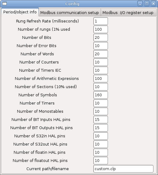
5.6. Konfigurationsfenster
Das Konfigurationsfenster zeigt den aktuellen Projektstatus und enthält die Registerkarten für die Modbus-Einrichtung.
6. SPS Objekte
6.1. KONTAKTE
Stellen Schalter oder Relaiskontakte dar. Sie werden durch den ihnen zugewiesenen variablen Buchstaben und die Nummer gesteuert.
The variable letter can be B, I, or Q and the number can be up to a three digit number, e.g. %I2, %Q3, or %B123. Variable I is controlled by a HAL input pin with a corresponding number. Variable B is for internal contacts, controlled by a B coil with a corresponding number. Variable Q is controlled by a Q coil with a corresponding number (like a relay with multiple contacts). E.g., if HAL pin classicladder.0.in-00 is true then %I0 N.O. contact would be on (closed, true, whatever you like to call it). If %B7 coil is energized (on, true, etc) then %B7 N.O. contact would be on. If %Q1 coil is energized then %Q1 N.O. contact would be on (and HAL pin classicladder.0.out-01 would be true).
-
N.O. Contact' -
 (Schließer) Ist die Variable mit false belegt, dann ist der Schalter aus.
-
N.C. Contact -
 (Normally Closed) When the variable is false the switch is on.
-
Rising Edge Contact - Wenn die Variable von false in true wechselt, wird der Schalter gepulst.
-
Falling Edge Contact - Wenn die Variable von true zu false wechselt, wird der Schalter gepulst eingeschaltet.
6.2. IEC-TIMER
Stellt neue Countdown-Timer dar. IEC-Timer ersetzen Timer und Monoflops.
IEC Timer haben 2 Kontakte.
-
I - Eingabekontakt
-
Q - Ausgangskontakt
Es gibt drei Modi - TON, TOF, TP.
-
TON - When timer input is true countdown begins and continues as long as input remains true. After countdown is done and as long as timer input is still true the output will be true.
-
TOF - Wenn die Timereingabe true ist, wird die Ausgabe auf true gesetzt. Wenn die Eingabe false ist, zählt der Timer herunter und setzt die Ausgabe auf false.
-
TP - Wenn der Timer-Eingang auf wahr gepulst oder wahr gehalten wird, setzt der Timer den Ausgang auf wahr, bis der Timer herunterzählt. (einmalig)
The time intervals can be set in multiples of 100&8239;ms, seconds, or minutes.
Es gibt auch Variablen für IEC-Timer, die in Vergleichs- oder Betriebsblöcken gelesen und/oder beschrieben werden können.
-
%TMxxx.Q - Timer beendet (Boolesch, Lesen/Schreiben)
-
%TMxxx.P - Timer-Voreinstellung (Lesen/Schreiben)
-
%TMxxx.V - Timer-Wert (lesender Schreibvorgang)
6.3. ZEITGLIEDER (engl. timers)
Repräsentiert Countdown-Timer. Dies ist veraltet und wird durch IEC Timers ersetzt.
Timer haben 4 Kontakte.
-
E - aktivieren (engl. enable) (Eingang) startet den Timer, wenn wahr, setzt zurück, wenn er falsch wird
-
C - Steuerung (engl. control) (Eingang) muss eingeschaltet sein, damit der Timer läuft (normalerweise mit E verbinden)
-
D - fertig (engl. done) (Ausgang) wahr, wenn der Timer abläuft und solange E wahr bleibt
-
R - läuft (engl. running) (Ausgang) true, wenn Timer läuft
Die Basis des Timers kann ein Vielfaches von Millisekunden, Sekunden oder Minuten sein.
Es gibt auch Variablen für Zeitgeber, die in Vergleichs- oder Operationsblöcken gelesen und/oder beschrieben werden können.
-
%Txx.R - Timer xx läuft (boolesch, nur Lesen)
-
%Txx.D - Timer xx fertig (Boolesch, nur lesbar)
-
%Txx.V - Timer xx aktueller Wert (Ganzzahl, nur lesbar)
-
%Txx.P - Timer xx voreingestellt (Ganzzahl, lesen oder schreiben)
6.4. KIPPSTUFEN (engl. monostables)
Repräsentieren die ursprünglichen One-Shot-Timer. Dies ist jetzt veraltet und wird durch IEC-Timer ersetzt.
Monostabile haben 2 Kontakte, I und R.
-
I - Eingang (Eingang) startet den Mono-Timer.
-
R - Running (Ausgang) ist wahr, während der Timer läuft.
The I contact is rising edge sensitive meaning it starts the timer only when changing from false to true (or off to on). While the timer is running the I contact can change with no effect to the running timer. R will be true and stay true till the timer finishes counting to zero. The timer base can be multiples of milliseconds, seconds, or minutes.
Es gibt auch Variablen für Kippstufen, die in Vergleichs- oder Operationsblöcken gelesen und/oder beschrieben werden können.
-
%Mxx.R - Kippstufe xx läuft (boolesch, nur lesbar)
-
%Mxx.V - Monostabiler xx aktueller Wert (ganze Zahl, schreibgeschützt)
-
%Mxx.P - Monostabile xx-Voreinstellung (Ganzzahl, Lesen oder Schreiben)
6.5. ZÄHLER (engl. counters)
Aufwärts-/Abwärtszähler darstellen.
Es gibt 7 Kontakte:
-
R - reset (Eingabe) setzt die Anzahl auf 0 zurück.
-
P - Voreinstellung (engl. preset) (Eingabe) setzt den Zähler auf die im Bearbeitungsmenü zugewiesene Voreinstellungsnummer.
-
U - Aufwärtszählung (Eingabe) fügt der Zählung eins hinzu.
-
D - Abwärtszählung (Eingang) subtrahiert eins von der Zählung.
-
E - under flow (output) ist wahr, wenn die Zählung von 0 auf 9999 übertragen wird.
-
D - done (Ausgabe) ist wahr, wenn die Anzahl gleich der Voreinstellung ist.
-
F - Überlauf (Ausgabe) ist wahr, wenn die Anzahl von 9999 auf 0 übertragen wird.
Die Aufwärts- und Abwärtszählkontakte sind flankenempfindlich, d. h. sie zählen nur, wenn der Kontakt von falsch auf wahr wechselt (oder von aus auf ein, wenn Sie das wünschen).
Der Bereich reicht von 0 bis 9999.
Es gibt auch Variablen für Zähler, die in Vergleichs- oder Operationsblöcken gelesen und/oder beschrieben werden können.
-
'%C'xx
.D- Counter xx done (Boolean, read only) -
'%C'xx
.E- Counter xx empty overflow (Boolean, read only_) -
'%C'xx
.F- Counter xx full overflow (Boolean, read only) -
'%C'xx
.V- Counter xx current value (integer, read or write) -
'%C'xx
.P- Counter xx preset (integer, read or write)
6.6. VERGLEICHEN
Für den arithmetischen Vergleich. Ist die Variable %XXX = zu dieser Zahl (oder der ausgewerteten Zahl)
The compare block will be true when comparison is true. You can use most math symbols:
-
+,-,*,/,=(standard math symbols) -
<(less than),>(greater than),<=(less or equal),>=(greater or equal),<>(not equal) -
(,)separate into groups example%IF1=2,&%IF2<5in pseudo code translates to if %IF1 is equal to 2 and %IF2 is less than 5 then the comparison is true. Note the comma separating the two groups of comparisons. -
^(exponent),%(modulus),&(and),|(or),. - -
ABS(absolute),MOY(French for average),AVG(average)
Zum Beispiel ABS(%W2)=1, MOY(%W1,%W2)<3.
No spaces are allowed in the comparison equation. For example %C0.V>%C0.P is a valid comparison expression while %C0.V > %CO.P is not a valid expression.
There is a list of Variables down the page that can be used for reading from and writing to ladder objects. When a new compare block is opened be sure and delete the # symbol when you enter a compare.
Um herauszufinden, ob die Wortvariable Nr. 1 kleiner als das 2-fache des aktuellen Wertes von Zähler Nr. 0 ist, lautet die Syntax wie folgt:
%W1<2*%C0.VUm herauszufinden, ob S32in Bit 2 gleich 10 ist, würde die Syntax lauten:
%IW2=10Hinweis: Compare verwendet das arithmetische Gleichheitszeichen und nicht das doppelte Gleichheitszeichen, an das Programmierer gewöhnt sind.
6.7. VARIABLENZUWEISUNG
For variable assignment, e.g. assign this number (or evaluated number) to this variable %xxx, there are two math functions MINI and MAXI that check a variable for maximum (0x80000000) and minimum values (0x07FFFFFFF) (think signed values) and keeps them from going beyond.
When a new variable assignment block is opened be sure to delete the # symbol when you enter an assignment.
Um der Timer-Voreinstellung von IEC Timer 0 den Wert 10 zuzuweisen, lautet die Syntax:
%TM0.P=10Um den Wert von 12 auf s32out Bit 3 zuzuweisen, wäre folgendes:
%QW3=12|
Anmerkung
|
When you assign a value to a variable with the variable assignment block the value is retained until you assign a new value using the variable assignment block. The last value assigned will be restored when LinuxCNC is started. |
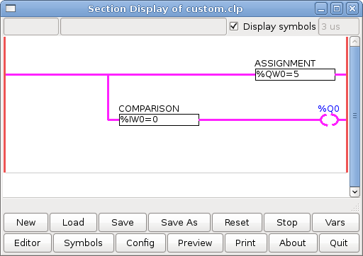
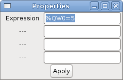
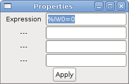
The following figure shows an Assignment and a Comparison Example. %QW0 is a S32out bit and %IW0 is a S32in bit. In this case the HAL pin classicladder.0.s32out-00 will be set to a value of 5 and when the HAL pin classicladder.0.s32in-00 is 0 the HAL pin classicladder.0.out-00 will be set to True.
6.8. SPULEN (engl. coils)
Spulen stellen Relaisspulen dar. Sie werden durch den ihnen zugewiesenen variablen Buchstaben und die Nummer gesteuert.
The variable letter can be B or Q and the number can be up to a three digit number, e.g., %Q3, or %B123. Q coils control HAL out pins, e.g. if %Q15 is energized then HAL pin classicladder.0.out-15 will be true. B coils are internal coils used to control program flow.
-
N.O. COIL' - Eine Relaisspule: Wenn die Spule erregt ist, wird ihr Kontakt, der normalerweise offen ist (kurz: N.O.), geschlossen (eingeschaltet, wahr, etc.) und der Strom kann passieren.
-
N.C. COIL' - Eine Relaisspule, die ihre Kontakte umkehrt: Wenn die Spule erregt wird, dann wird der normalerweise geschlossene Kontakt (engl. kurz: N.C.) geöffnet (ausgeschaltet, falsch, usw.) und der Stromfluss wird unterbrochen.
-
SET COIL - Eine Relaisspule mit verriegelten Kontakten: Wenn die Spule erregt ist, wird der Kontakt geschlossen und bleibt dies.
-
RESET COIL - (eine Relaisspule mit selbsthaltenden Kontakten) Wenn die Spule erregt ist, wird der N.0.-Kontakt offen gehalten.
-
JUMP COIL - A goto coil: When coil is energized then the ladder program jumps to a rung (in the CURRENT section) - jump points are designated by a rung label. (Add rung labels in the section display, top left label box.)
-
CALL COIL - A gosub coil: When coil is energized then the program jumps to a subroutine section designated by a subroutine number - subroutines are designated SR0 to SR9 (designate them in the section manager).
|
Warnung
|
Wenn Sie einen NC-Kontakt mit einer NC-Spule verwenden, funktioniert die Logik (wenn die Spule erregt ist, wird der Kontakt geschlossen), aber das ist wirklich schwer zu verstehen! |
6.8.1. SPRUNGSPULE (engl. jump coil)
Eine JUMP COIL wird verwendet, um zu einem anderen Abschnitt zu springen, wie ein goto in der Programmiersprache BASIC.
If you look at the top left of the sections display window you will see a small label box and a longer comment box beside it. Now go to Editor→Modify then go back to the little box, type in a name.
Go ahead and add a comment in the comment section. This label name is the name of this rung only and is used by the JUMP COIL to identify where to go.
Wenn Sie eine JUMP COIL platzieren, fügen Sie sie an der äußersten rechten Position ein und ändern die Beschriftung in die Sprosse, zu der Sie JUMPEN wollen.
6.8.2. RUFSPULE (engl. call coil)
Eine CALL COIL wird verwendet, um zu einem Unterprogramm zu gelangen und dann zurückzukehren, wie ein gosub in der Programmiersprache BASIC.
Gehen Sie zum Fenster Abschnittsmanager und klicken Sie auf die Schaltfläche Abschnitt hinzufügen. Sie können diesen Abschnitt benennen, die Sprache (Kontaktplan oder sequentiell) und den Typ (Haupt- oder Unterprogramm) auswählen.
Select a subroutine number (SR0 for example). An empty section will be displayed and you can build your subroutine.
Wenn Sie das getan haben, gehen Sie zurück zum Abschnittsmanager und klicken Sie auf Ihren Hauptabschnitt (Standardname prog1).
Jetzt können Sie eine CALL COIL in Ihr Programm einfügen. CALL COILs sind an der äußersten rechten Position im Strompfad zu platzieren.
Vergessen Sie nicht, die Beschriftung in die Nummer des Unterprogramms zu ändern, die Sie zuvor gewählt haben.
7. ClassicLadder Variablen
Diese Variablen werden in COMPARE oder OPERATE verwendet, um Informationen über Kontaktplanobjekte zu erhalten oder deren Spezifikationen zu ändern, z. B. um einen Zähler zu ändern oder um zu sehen, ob ein Timer fertig ist.
Liste der Variablen :
-
%Bxxx - Bit memory xxx (Boolean) -
%Wxxx - Word memory xxx (32 bits signed integer) -
%IWxxx - Word memory xxx (S32 in pin) -
%QWxxx - Word memory xxx (S32 out pin) -
%IFxx - Word memory xx (Float in pin) (converted to S32 in ClassicLadder) -
%QFxx - Word memory xx (Float out pin) (converted to S32 in ClassicLadder) -
%T`__xx__.R` - Timer xx running (Boolean, user read only) -
%T`__xx__.D` - Timer xx done (Boolean, user read only) -
%T`__xx__.V` - Timer xx current value (integer, user read only) -
%T`__xx__.P` - Timer xx preset (integer) -
%TM`__xxx__.Q` - Timer xxx done (Boolean, read write) -
%TM`__xxx__.P` - Timer xxx preset (integer, read write) -
%TM`__xxx__.V` - Timer xxx value (integer, read write) -
%M`__xx__.R` - Monostable xx running (Boolean) -
%M`__xx__.V` - Monostable xx current value (integer, user read only) -
%M`__xx__.P` - Monostable xx preset (integer) -
%C`__xx__.D` - Counter xx done (Boolean, user read only) -
%C`__xx__.E` - Counter xx empty overflow (Boolean, user read only) -
%C`__xx__.F` - Counter xx full overflow (Boolean, user read only) -
%C`__xx__.V` - Counter xx current value (integer) -
%C`__xx__.P` - Counter xx preset (integer) -
%Ixxx - Physical input xxx (Boolean) (HAL input bit) -
%Qxxx - Physical output xxx (Boolean) (HAL output bit) -
%Xxxx - Activity of step xxx (sequential language) -
%X`__xxx__.V` - Time of activity in seconds of step xxx (sequential language) -
%Exx - Errors (Boolean, read write(will be overwritten)) -
Indexed or vectored variables - These are variables indexed by another variable. Some might call this vectored variables. Example:
%W0[%W4]=> if %W4 equals 23 it corresponds to %W23
8. GRAFCET (State Machine) Programmierung
|
Warnung
|
This is probably the least used and most poorly understood feature of ClassicLadder. Sequential programming is used to make sure a series of ladder events always happen in a prescribed order. Sequential programs do not work alone. There is always a ladder program as well that controls the variables. Here are the basic rules governing sequential programs: |
-
Rule 1 : Initial situation - The initial situation is characterized by the initial steps which are by definition in the active state at the beginning of the operation. There shall be at least one initial step.
-
Rule 2 : R2, Clearing of a transition - A transition is either enabled or disabled. It is said to be enabled when all immediately preceding steps linked to its corresponding transition symbol are active, otherwise it is disabled. A transition cannot be cleared unless it is enabled, and its associated transition condition is true.
-
Regel 3 : R3, Entwicklung aktiver Schritte - Die Löschung eines Übergangs führt gleichzeitig zum aktiven Zustand des/der unmittelbar folgenden Schrittes/Schritte und zum inaktiven Zustand des/der unmittelbar vorangehenden Schrittes/Schritte.
-
Regel 4 : R4, Gleichzeitige Löschung von Übergängen - Alle gleichzeitig gelöschten Übergänge werden gleichzeitig gelöscht.
-
Regel 5 : R5, Gleichzeitiges Aktivieren und Deaktivieren eines Schrittes - Wenn während des Betriebs ein Schritt gleichzeitig aktiviert und deaktiviert wird, hat die Aktivierung Vorrang.
This is the SEQUENTIAL editor window. (Starting from the top left):
Selector arrow, Eraser
Ordinary step, Initial (Starting) step
Transition, Step and Transition
Transition Link-Downside, Transition Link-Upside
Pass-through Link-Downside, Pass-through Link-Upside Jump
Link, Comment Box
-
ORDINARY STEP - hat für jeden eine eindeutige Nummer
-
STARTING STEP - a sequential program must have one. This is where the program will start.
-
TRANSITION - shows the variable that must be true for control to pass through to the next step.
-
STEP AND TRANSITION - combined for convenience
-
TRANSITION LINK-DOWNSIDE - teilt den Logikfluss in eine von zwei möglichen Linien auf, je nachdem, welcher der nächsten Schritte zuerst wahr ist (denken Sie an die ODER-Logik)
-
TRANSITION LINK=UPSIDE - verbindet zwei (ODER) Logiklinien wieder zu einer
-
PASS-THROUGH-LINK-DOWNSIDE - teilt den Logikfluss in zwei Zeilen auf, dass BEIDE wahr sein müssen, um fortzufahren (Think AND logic)
-
PASS-THROUGH-LINK-UPSIDE - kombiniert zwei gleichzeitige (UND logische) Logiklinien wieder zusammen
-
JUMP LINK - verbindet Schritte, die nicht untereinander liegen, z. B. das Verbinden des letzten Schritts mit dem ersten
-
COMMENT BOX - wird verwendet, um Kommentare hinzuzufügen
To use links, you must have steps already placed. Select the type of link, then select the two steps or transactions one at a time. It takes practice!
With sequential programming: The variable %X`__xxx__ (e.g., `%X5) is used to see if a step is active. The variable %X`__xxx__.V` (e.g., %X5.V) is used to see how long the step has been active. The %X and %X.v variables are use in LADDER logic. The variables assigned to the transitions (e.g., %B) control whether the logic will pass to the next step. After a step has become active the transition variable that caused it to become active has no control of it anymore. The last step has to JUMP LINK back only to the beginning step.
9. Modbus
Zu beachtende Punkte:
-
Modbus is a non-realtime program so it might have latency issues on a heavily laden computer.
-
Modbus eignet sich nicht wirklich für harte Echtzeit-Ereignisse wie die Positionssteuerung von Motoren oder die Steuerung von Notausschaltern.
-
Das ClassicLadder GUI muss ausgeführt werden, damit Modbus ausgeführt werden kann.
-
Modbus ist noch nicht ganz fertig, so dass nicht alle Modbus-Funktionen zur Verfügung stehen.
To get MODBUS to initialize you must specify that when loading the ClassicLadder non-realtime program.
loadusr -w classicladder --modmaster myprogram.clpThe -w makes HAL wait until you close ClassicLadder before closing realtime session. ClassicLadder also loads a TCP modbus slave if you add --modserver on command line.
-
1 - Spulen lesen
-
2 - Eingänge lesen
-
3 - Halteregister lesen
-
4 - Eingaberegister lesen
-
5 - einzelne Spulen schreiben
-
6 - Einzelnes Register schreiben
-
8 - Echo-Test
-
15 - mehrere Spulen schreiben
-
16 - mehrere Register schreiben
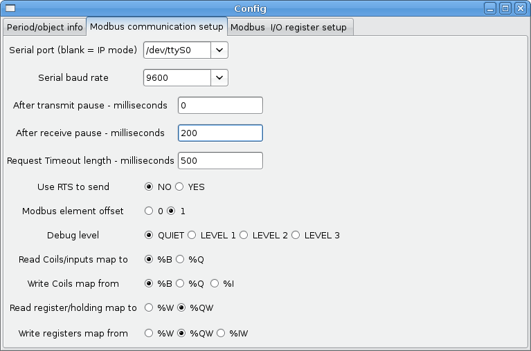
If you do not specify a --modmaster when loading the ClassicLadder non-realtime program this page will not be displayed.
-
SERIAL PORT - For IP blank. For serial the location/name of serial driver, e.g., /dev/ttyS0 ( or /dev/ttyUSB0 for a USB-to-serial converter).
-
SERIAL SPEED - Sollte auf Geschwindigkeit eingestellt sein, für die der Slave eingestellt ist - 300, 600, 1200, 2400, 4800, 9600, 19200, 38400, 57600, 115200 werden unterstützt.
-
PAUSE AFTER TRANSMIT - Pause (Millisekunden) nach dem Senden und vor dem Empfang der Antwort, einige Geräte benötigen mehr Zeit (z. B. USB-zu-Seriell-Konverter).
-
PAUSE INTER-FRAME - Pause (Millisekunden) nach Erhalt der Antwort vom Slave. Dadurch wird der Arbeitszyklus von Anforderungen festgelegt (es ist eine Pause für JEDE Anforderung).
-
REQUEST TIMEOUT LENGTH - Länge (Millisekunden) der Zeit, bevor wir entscheiden, dass der Slave nicht geantwortet hat.
-
MODBUS ELEMENT OFFSET - wird verwendet, um die Elementnummern um 1 zu kompensieren (für Hersteller, die Unterschiede nummerieren).
-
DEBUG LEVEL - Setzen Sie dies auf 0-3 (0, um das Drucken von Debug-Informationen neben No-Response-Fehlern zu stoppen).
-
READ COILS/INPUTS MAP TO - Wählen Sie, welche Variablen die gelesenen Spulen/Eingänge aktualisieren sollen. (B oder Q).
-
WRITE COILS MAP TO - Wählen Sie aus, von welchen Variablen, von denen Schreibspulen aktualisiert werden sollen (B, Q oder I).
-
READ REGISTERS/HOLDING - Wählen Sie aus, welche Variablen durch das Lesen von Registern aktualisiert werden sollen (W oder QW).
-
WRITE REGISTERS MAP TO - Wählen Sie aus, von welchen Variablen die Leseregister aktualisiert werden (W, QW oder IW).
-
SLAVE ADDRESS - For serial the slaves ID number usually settable on the slave device (usually 1-256). For IP the slave IP address plus optionally the port number.
-
TYPE ACCESS - Dies wählt den MODBUS-Funktionscode aus, der an den Slave gesendet werden soll (z. B. welche Art von Anfrage).
-
COILS / INPUTS - Eingänge und Spulen (Bits) werden aus I-, B- oder Q-Variablen gelesen / geschrieben (Benutzerauswahl).
-
REGISTERS (WORDS) - Register (Wörter/Zahlen) werden IW-, W- oder QW-Variablen zugeordnet (Benutzerauswahl).
-
1st MODBUS ELEMENT - Die Adresse (oder Registernummer) des ersten Elements in einer Gruppe (Denken Sie daran, MODBUS ELEMENT OFFSET richtig einzustellen).
-
ANZAHL DER ELEMENTE - Die Anzahl der Elemente in dieser Gruppe.
-
LOGIC - Sie können die Logik hier umkehren.
-
1st%I%Q IQ WQ MAPPED - Dies ist die Startnummer von %B, %I, %Q, %W, %IW oder %QW Variablen, die auf/von der Modbus-Elementgruppe zugeordnet werden (beginnend mit der ersten Modbus-Elementnummer).
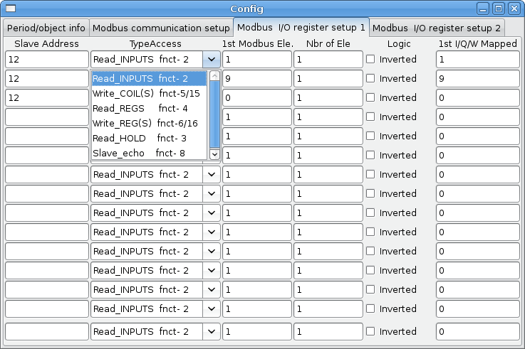
Im obigen Beispiel: Portnummer - für meinen Computer war /dev/ttyS0 meine serielle Schnittstelle.
Die serielle Geschwindigkeit ist auf 9600 Baud eingestellt.
Die Slave-Adresse ist auf 12 gesetzt (auf meinem VFD kann ich dies von 1-31 einstellen, was bedeutet, dass ich auf einem System maximal mit 31 VFDs sprechen kann).
The first line is set up for 8 input bits starting at the first register number (register 1). So register numbers 1-8 are mapped onto ClassicLadder’s %B variables starting at %B1 and ending at %B8.
Die zweite Zeile ist für 2 Ausgangsbits ab der neunten Registernummer (Register 9) eingestellt, so dass die Registernummern 9-10 auf die %Q-Variablen von ClassicLadder abgebildet werden, die bei %Q9 beginnen und bei %Q10 enden.
The third line is set to write 2 registers (16 bits each) starting at the 0th register number (register 0), so register numbers 0-1 are mapped onto ClassicLadder’s %W variables starting at %W0 ending at %W1.
It’s easy to make an off-by-one error as sometimes the modbus elements are referenced starting at one rather then 0 (actually by the standard that is the way it’s supposed to be!). You can use the modbus element offset radio button to help with this.
In den Unterlagen zu Ihrem Modbus-Slave-Gerät finden Sie Informationen darüber, wie die Register aufgebaut sind - es gibt keine Standardmethode.
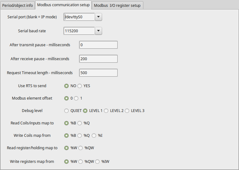
Die Parameter SERIAL PORT, PORT SPEED, PAUSE und DEBUG-Level können geändert werden (beim Schließen des Konfigurationsfensters werden die Werte übernommen, die Radio-Buttons gelten jedoch sofort).
To use the echo function select the echo function and add the slave number you wish to test. You don’t need to specify any variables.
The number 257 will be sent to the slave number you specified and the slave should send it back. You will need to have ClassicLadder running in a terminal to see the message.
10. MODBUS-Einstellungen
Seriell:
-
ClassicLadder verwendet das RTU-Protokoll (nicht ASCII).
-
8 Datenbits, keine Parität und 1 Stoppbit werden auch als 8-N-1 bezeichnet.
-
Baud rate must be the same for slave and master. ClassicLadder can only have one baud rate so all the slaves must be set to the same rate.
-
Das Pausenintervall ist die Zeitspanne, die nach dem Empfang einer Antwort pausiert wird.
-
MODBUS_TIME_AFTER_TRANSMIT ist die Länge der Pause nach dem Senden einer Anfrage und vor dem Empfang einer Antwort (dies hilft offenbar bei langsamen USB-Wandlern).
10.1. MODBUS-Info
-
ClassicLadder can use distributed inputs/outputs on modules using the Modbus protocol ("master": polling slaves).
-
Die Slaves und ihre I/O können im Konfigurationsfenster konfiguriert werden.
-
Es sind 2 exklusive Modi verfügbar: Ethernet mit Modbus/TCP und seriell mit Modbus/RTU.
-
Es wird keine Parität verwendet.
-
Wenn kein Portname für die serielle Schnittstelle eingestellt ist, wird der TCP/IP-Modus verwendet…
-
Die Slave-Adresse ist die Slave-Adresse (Modbus/RTU) oder die IP-Adresse.
-
Die IP-Adresse kann durch die zu verwendende Portnummer ergänzt werden (xx.xx.xx.xx:pppp), andernfalls wird standardmäßig der Port 9502 verwendet.
-
2 products have been used for tests: a Modbus/TCP one (Adam-6051, https://www.advantech.com) and a serial Modbus/RTU one (http://www.ipac.ws).
-
Siehe Beispiele: adam-6051 und modbus_rtu_serial.
-
Web links: https://www.modbus.org and this interesting one: http://www.iatips.com/modbus.html
-
MODBUS TCP SERVER ENTHALTEN
-
ClassicLadder hat einen Modbus/TCP-Server integriert. Der Standard-Port ist 9502. (der vorherige Standard 502 erfordert, dass die Anwendung mit Root-Rechten gestartet werden muss).
-
Die Liste der unterstützten Modbus-Funktionscodes lautet: 1, 2, 3, 4, 5, 6, 15 und 16.
-
Die Korrespondenztabelle der Modbus-Bits und -Worte ist eigentlich nicht parametrisch und entspricht direkt den Variablen %B und %W.
Weitere Informationen zum Modbus-Protokoll finden Sie im Internet.
10.2. Kommunikationsfehler
If there is a communication error, a warning window will pop up (if the GUI is running) and %E0 will be true. Modbus will continue to try to communicate. The %E0 could be used to make a decision based on the error. A timer could be used to stop the machine if timed out, etc.
11. Fehlersuche bei Modbus-Problemen
A good reference for the protocol: https://www.modbus.org/docs/Modbus_Application_Protocol_V1_1b.pdf. If you run linuxcnc/classicladder from a terminal, it will print the Modbus commands and slave responses.
Hier wird der ClassicLadder so eingestellt, dass er den Slave 1 auffordert, die Holding-Register (Funktionscode 3) ab Adresse 8448 (0x2100) zu lesen. Wir fordern die Rückgabe von 1 (2 Byte breiten) Datenelement an. Wir ordnen es einer ClassicLadder-Variablen zu, startend bei 2.
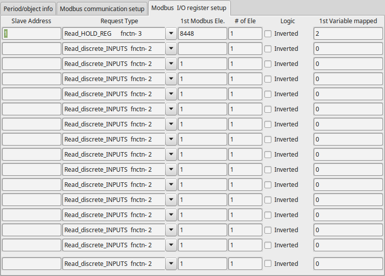
Hinweis in diesem Bild haben wir die Debug-Ebene auf 1 gesetzt, so dass Modbus-Nachrichten an das Terminal ausgegeben werden. Wir haben unsere Lese- und Schreibregister den %W-Variablen von ClassicLadder zugeordnet, so dass unsere zurückgegebenen Daten in %W2 sind, wie in dem anderen Bild, in dem wir die Daten ab dem 2. Element zugeordnet haben.
11.1. Anfrage
Betrachten wir ein Beispiel für das Lesen eines Hold-Registers bei 8448 Decimal (0x2100 Hex).
Blick in die Modbus-Protokollreferenz:
| Name | Anzahl Bytes | Wert (hex) |
|---|---|---|
Funktionscode |
(1 Byte) |
3 (0x03) |
Startadresse |
(2 Bytes) |
0 - 65535 (0x0000 bis 0xFFFF) |
Anzahl von Registern |
(2 Bytes) |
1 bis 125 (0x7D) |
Prüfsumme |
(2 Bytes) |
Automatisch berechnet |
Hier ist ein Beispiel für einen gesendeten Befehl, wie er im Terminal ausgedruckt wird (alles in Hex):
INFO CLASSICLADDER- Modbus I/O module to send: Lgt=8 <- Slave address-1 Function code-3 Data-21 0 0 1 8E 36Bedeutung (Hex):
-
Lgt = 8 = Nachricht ist 8 Bytes lang, einschließlich Slave-Nummer und Prüfsummen-Nummer
-
Slave-Nummer = 1 (0x1) = Slave-Adresse 1
-
Funktionscode = 3 (0x3) = Halteregister lesen
-
Start bei Adresse = Highbyte 33 (0x21) Lowbyte 0 (0x00) = kombinierte Adresse = 8448 (0x2100)
-
Anzahl der Register = 1 (0x1) = 1 2-Byte-Register zurückgeben (Halte- und Leseregister sind immer 2 Byte breit)
-
Prüfsumme = Highbyte 0x8E Lowbyte 0x36 = (0x8E36)
11.2. Fehlerreaktion
Bei einer Fehlerantwort sendet er den Funktionscode plus 0x80, einen Fehlercode und eine Prüfsumme. Eine Fehlerantwort zu erhalten bedeutet, dass der Slave den Anforderungsbefehl sieht, aber keine gültigen Daten liefern kann. Schauen Sie in der Modbus-Protokollreferenz nach:
| Name | Anzahl Bytes | Wert (hex) |
|---|---|---|
Fehlercode |
1 Byte |
131 (0x83) |
Ausnahmecode |
1 Byte |
1-4 (0x01 bis 0x04) |
Prüfsumme |
(2 Bytes) |
Automatisch berechnet |
Bedeutung des Ausnahmecodes:
-
1 - illegal Funktion
-
2 - unzulässige Datenadresse
-
3 - unzulässiger Datenwert
-
4 - Ausfall des Slave-Geräts
Hier ist ein Beispiel für einen empfangenen Befehl, wie er im Terminal ausgedruckt wird (alles in Hex):
INFO CLASSICLADDER- Modbus I/O module received: Lgt=5 -> (Slave address-1 Function code-83 ) 2 C0 F1Bedeutung (Hex):
-
Slave-Nummer = 1 (0x1) = Slave-Adresse 1
-
Funktionscode = 131 (0x83) = Fehler beim Lesen des Holdingregisters
-
Fehlercode = 2 (0x2) = unzulässige Datenadresse angefordert
-
Prüfsumme = (0x8E36)
11.3. Datenantwort
Blick auf das Protokoll über die Antwort:
| Name | Anzahl Bytes | Wert (hex) |
|---|---|---|
Funktionscode |
1 Byte |
3 (0x03) |
Anzahl der Bytes |
1 Byte |
2 x N* |
Wert des Registers |
N* x 2 Bytes |
Rückgabewert der angeforderten Adresse |
Prüfsumme |
(2 Bytes) |
automatisch berechnet |
*N = Number of registers
Hier ist ein Beispiel für einen empfangenen Befehl, wie er im Terminal ausgedruckt wird (alles in Hex):
INFO CLASSICLADDER- Modbus I/O module received: Lgt=7 -> (Slave address-1 Function code-3 2 0 0 B8 44)Bedeutung (Hex):
-
Slave-Nummer = 1 (0x1) = Slave-Adresse 1
-
Angeforderter Funktionscode = 3 (0x3) = Lesen des Holdingregisters angefordert
-
Anzahl der Byte-Register = 2 (0x1) = Rückgabe von 2 Bytes (jeder Registerwert ist 2 Bytes breit)
-
Wert des Highbytes = 0 (0x0) = Highbyte-Wert der Adresse 8448 (0x2100)
-
Wert des Lowbyte = 0 (0x0) = Wert des Highbyte der Adresse 8448 (0x2100)
-
Prüfsumme = (0xB844)
(High- und Low-Bytes werden zu einem 16-Bit-Wert kombiniert und dann an die ClassicLadder-Variable übertragen). Leseregister können auf %W oder %QW (interner Speicher oder HAL-Out-Pins) abgebildet werden. Schreibregister können auf %W, %QW oder %IW (interner Speicher, HAL-Out-Pins oder HAL-In-Pins) abgebildet werden: Wenn mehrere Register in einem Lese-/Schreibvorgang angefordert werden, sind die Variablennummern nach der ersten fortlaufend.
11.4. MODBUS-Fehler
-
In Vergleichsblöcken wird die Funktion %W=ABS(%W1-%W2) akzeptiert, aber nicht korrekt berechnet. Nur %W0=ABS(%W1) ist derzeit zulässig.
-
When loading a ladder program it will load Modbus info but will not tell ClassicLadder to initialize Modbus. You must initialize Modbus when you first load the GUI by adding --modmaster.
-
If the section manager is placed on top of the section display, across the scroll bar and exit is clicked the non-realtime program crashes.
-
Wenn Sie --modmaster verwenden, müssen Sie gleichzeitig das Kontaktplanprogramm laden, sonst funktioniert nur TCP.
-
das Lesen/Schreiben mehrerer Register im Modbus weist Prüfsummenfehler auf.
12. Einrichten von ClassicLadder
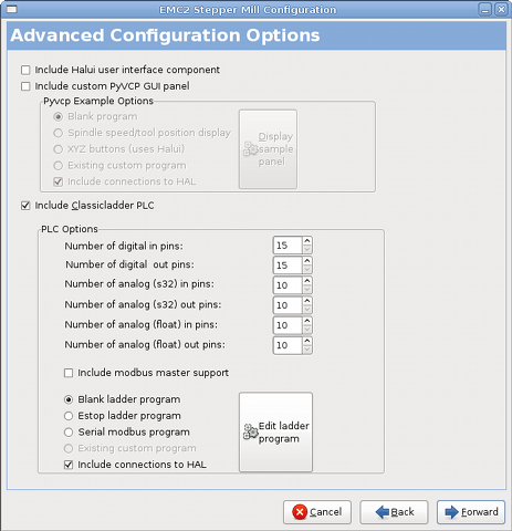
In this section we will cover the steps needed to add ClassicLadder to a StepConf Wizard generated config. On the advanced Configuration Options page of StepConf Wizard check off "Include ClassicLadder PLC".
12.1. Hinzufügen der Module
If you used the StepConf Wizard to add ClassicLadder you can skip this step.
To manually add ClassicLadder you must first add the modules. This is done by adding a couple of lines to the custom.hal file.
Diese Zeile lädt das Echtzeitmodul:
loadrt classicladder_rt
Diese Zeile fügt dem Servo-Thread die Funktion ClassicLadder hinzu:
addf classicladder.0.refresh servo-thread
12.2. Hinzufügen der Kontaktplanlogik
Now start up your config and select "File/Ladder Editor" to open up the ClassicLadder GUI. You should see a blank Section Display and Sections Manager window as shown above. In the Section Display window open the Editor. In the Editor window select Modify. Now a Properties window pops up and the Section Display shows a grid. The grid is one rung of ladder. The rung can contain branches. A simple rung has one input, a connector line and one output. A rung can have up to six horizontal branches. While it is possible to have more than one circuit in a run the results are not predictable.
Now click on the N.O. input in the Editor Window.
Klicken Sie nun in das obere linke Raster, um den N.O.-Eingang in der Leiter zu platzieren.
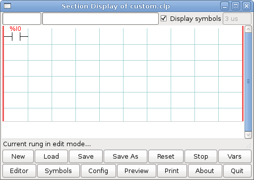
Repeat the above steps to add a N.O. output to the upper right grid and use the Horizontal Connection to connect the two. It should look like the following. If not, use the Eraser to remove unwanted sections.
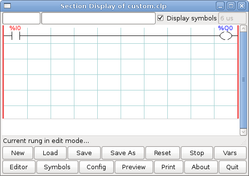
Klicken Sie nun im Editor-Fenster auf die Schaltfläche OK. Jetzt sollte Ihre Abschnittsanzeige wie folgt aussehen:
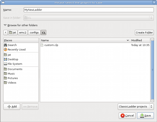
To save the new file select Save As and give it a name. The .clp extension will be added automatically. It should default to the running config directory as the place to save it.
Again if you used the StepConf Wizard to add ClassicLadder you can skip this step.
To manually add a ladder you need to add add a line to your custom.hal file that will load your ladder file. Close your LinuxCNC session and add this line to your custom.hal file.
loadusr -w classicladder --nogui MyLadder.clp
Now if you start up your LinuxCNC config your ladder program will be running as well. If you select "File/Ladder Editor", the program you created will show up in the Section Display window.