1. File Locations
LinuxCNC looks for the configuration and G-code files in a specific place. The location depends on how you run LinuxCNC.
1.1. Installed
If your running LinuxCNC from the Live CD or you installed via a .deb and use the configuration picker LinuxCNC from the menu LinuxCNC looks in the following directories:
-
The LinuxCNC directory is located at /home/user-name/linuxcnc.
-
The Configuration directories are located at /home/user-name/linuxcnc/configs.
-
Configuration files are located at /home/user-name/linuxcnc/configs/name-of-config.
-
-
G-code files are located at /home/user-name/linuxcnc/nc_files'.
For example for a configuration called Mill and a user name Fred the directory and file structure would look like this.
-
/home/fred/linuxcnc
-
/home/fred/linuxcnc/nc_files
-
/home/fred/linuxcnc/configs/mill
-
/home/fred/linuxcnc/configs/mill/mill.ini
-
/home/fred/linuxcnc/configs/mill/mill.hal
-
/home/fred/linuxcnc/configs/mill/mill.var
-
/home/fred/linuxcnc/configs/mill/tool.tbl
-
1.2. Command Line
If you run LinuxCNC from the command line and specify the name and location of the INI file the file locations can be in a different place. To view the options for running LinuxCNC from the command line run linuxcnc -h.
|
Note
|
Optional locations for some files can be configured in the INI file. See the
<<sub:ini:sec:display,[DISPLAY]>> section and the
<<sub:ini:sec:rs274ngc,[RS274NGC]>> section. |
2. Files
Each configuration directory requires at least the following files:
-
An INI file .ini
-
A HAL file .hal or HALTCL file .tcl specified in the HAL section of the INI file.
|
Note
|
Other files may be required for some GUIs. |
Optionally you can also have:
-
A Variables file .var
-
If you omit a .var file in a directory but include
<<sub:ini:sec:rs274ngc,[RS274NGC]>>PARAMETER_FILE=somefilename.var, the file will be created for you when LinuxCNC starts. -
If you omit a .var file and omit the item [RS274NGC] PARAMETER_FILE, a var file named rs274ngc.var will be created when LinuxCNC starts. There may be some confusing messages if [RS274NGC]PARAMETER_FILE is omitted.
-
-
A Tool Table file .tbl if
<<sub:ini:sec:emcmot,[EMCMOT]>>TOOL_TABLE has been specified in the INI file. Some configurations do not need a tool table.
3. Stepper Systems
3.1. Base Period
BASE_PERIOD is the heartbeat of your LinuxCNC computer.
[This
section refers to using stepgen, LinuxCNC’s built-in
step generator. Some hardware devices have their own step
generator and do not use LinuxCNC’s built-in one. In that case, refer to
your hardware manual.]
Every period, the
software step generator decides if it is time for another step pulse.
A shorter period will allow you to generate more pulses per second,
within limits. But if you go too short, your computer will spend so
much time generating step pulses that everything else will slow to a
crawl, or maybe even lock up. Latency and stepper drive requirements
affect the shortest period you can use.
Worst case latencies might only happen a few times a minute, and the odds of bad latency happening just as the motor is changing direction are low. So you can get very rare errors that ruin a part every once in a while and are impossible to troubleshoot.
The simplest way to avoid this problem is to choose a BASE_PERIOD that is the sum of the longest timing requirement of your drive, and the worst case latency of your computer. This is not always the best choice. For example, if you are running a drive with a 20 µs direction signal hold time requirement, and your latency test said you have a maximum latency of 11 µs , then if you set the BASE_PERIOD to 20+11 = 31 µs you get a not-so-nice 32,258 steps per second in one mode and 16,129 steps per second in another mode.
The problem is with the 20 µs hold time requirement. That plus the 11 µs
latency is what forces us to use a slow 31 µs period. But the LinuxCNC
software step generator has some parameters that let you increase the
various times from one period to several. For example, if steplen
[steplen
refers to a parameter that adjusts the performance of LinuxCNC’s built-in step generator,
stepgen, which is a HAL component. This parameter adjusts the length of the
step pulse itself. Keep reading, all will be explained eventually.]
is
changed from 1 to 2, then there will be two periods between the
beginning and end of the step pulse. Likewise, if dirhold
[dirhold
refers to a parameter that adjusts the length of the direction hold time.]
is
changed from 1 to 3, there will be at least three periods between the step
pulse and a change of the direction pin.
If we can use dirhold to meet the 20 µs hold time requirement, then the next longest time is the 4.5 µs high time. Add the 11 µs latency to the 4.5 µs high time, and you get a minimum period of 15.5 µs . When you try 15.5 µs , you find that the computer is sluggish, so you settle on 16 µs . If we leave dirhold at 1 (the default), then the minimum time between step and direction is the 16 µs period minus the 11 µs latency = 5 µs , which is not enough. We need another 15 µs . Since the period is 16 µs , we need one more period. So we change dirhold from 1 to 2. Now the minimum time from the end of the step pulse to the changing direction pin is 5+16=21 µs , and we don’t have to worry about the drive stepping the wrong direction because of latency.
For more information on stepgen see the stepgen section.
3.2. Step Timing
Step Timing and Step Space on some drives are different. In this case the Step point becomes important. If the drive steps on the falling edge then the output pin should be inverted.
4. Servo Systems
4.1. Basic Operation
Servo systems are capable of greater speed and accuracy than equivalent stepper systems, but are more costly and complex. Unlike stepper systems, servo systems require some type of position feedback device, and must be adjusted or tuned, as they don’t quite work right out of the box as a stepper system might. These differences exist because servos are a closed loop system, unlike stepper motors which are generally run open loop. What does closed loop mean? Let’s look at a simplified diagram of how a servomotor system is connected.
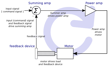
This diagram shows that the input signal (and the feedback signal) drive the summing amplifier, the summing amplifier drives the power amplifier, the power amplifier drives the motor, the motor drives the load (and the feedback device), and the feedback device (and the input signal) drive the motor. This looks very much like a circle (a closed loop) where A controls B, B controls C, C controls D, and D controls A.
If you have not worked with servo systems before, this will no doubt seem a
very strange idea at first, especially as compared to more normal electronic
circuits, where the inputs proceed smoothly to the outputs, and never go
back.
[If it helps, the closest equivalent to this in the digital
world are state machines, sequential machines and so forth, where what
the outputs are doing now depends on what the inputs (and the outputs)
were doing before. If it doesn’t help, then nevermind.]
If everything
controls everything else, how can that ever work, who’s in
charge? The answer is that LinuxCNC can control this system,
but it has to do it by choosing one of several control methods.
The control method that LinuxCNC uses, one of the simplest and best,
is called PID.
PID stands for Proportional, Integral, and Derivative. The Proportional value determines the reaction to the current error, the Integral value determines the reaction based on the sum of recent errors, and the Derivative value determines the reaction based on the rate at which the error has been changing. They are three common mathematical techniques that are applied to the task of getting a working process to follow a set point. In the case of LinuxCNC the process we want to control is actual axis position and the set point is the commanded axis position.

By tuning the three constants in the PID controller algorithm, the controller can provide control action designed for specific process requirements. The response of the controller can be described in terms of the responsiveness of the controller to an error, the degree to which the controller overshoots the set point and the degree of system oscillation.
4.2. Proportional term
The proportional term (sometimes called gain) makes a change to the output that is proportional to the current error value. A high proportional gain results in a large change in the output for a given change in the error. If the proportional gain is too high, the system can become unstable. In contrast, a small gain results in a small output response to a large input error. If the proportional gain is too low, the control action may be too small when responding to system disturbances.
In the absence of disturbances, pure proportional control will not settle at its target value, but will retain a steady state error that is a function of the proportional gain and the process gain. Despite the steady-state offset, both tuning theory and industrial practice indicate that it is the proportional term that should contribute the bulk of the output change.
4.3. Integral term
The contribution from the integral term (sometimes called reset) is proportional to both the magnitude of the error and the duration of the error. Summing the instantaneous error over time (integrating the error) gives the accumulated offset that should have been corrected previously. The accumulated error is then multiplied by the integral gain and added to the controller output.
The integral term (when added to the proportional term) accelerates the movement of the process towards set point and eliminates the residual steady-state error that occurs with a proportional only controller. However, since the integral term is responding to accumulated errors from the past, it can cause the present value to overshoot the set point value (cross over the set point and then create a deviation in the other direction).
4.4. Derivative term
The rate of change of the process error is calculated by determining the slope of the error over time (i.e., its first derivative with respect to time) and multiplying this rate of change by the derivative gain.
The derivative term slows the rate of change of the controller output and this effect is most noticeable close to the controller set point. Hence, derivative control is used to reduce the magnitude of the overshoot produced by the integral component and improve the combined controller-process stability.
4.5. Loop tuning
If the PID controller parameters (the gains of the proportional, integral and derivative terms) are chosen incorrectly, the controlled process input can be unstable, i.e., its output diverges, with or without oscillation, and is limited only by saturation or mechanical breakage. Tuning a control loop is the adjustment of its control parameters (gain/proportional band, integral gain/reset, derivative gain/rate) to the optimum values for the desired control response.
4.6. Manual tuning
A simple tuning method is to first set the I and D values to zero. Increase the P until the output of the loop oscillates, then the P should be set to be approximately half of that value for a quarter amplitude decay type response. Then increase I until any offset is correct in sufficient time for the process. However, too much I will cause instability. Finally, increase D, if required, until the loop is acceptably quick to reach its reference after a load disturbance. However, too much D will cause excessive response and overshoot. A fast PID loop tuning usually overshoots slightly to reach the set point more quickly; however, some systems cannot accept overshoot, in which case an over-damped closed-loop system is required, which will require a P setting significantly less than half that of the P setting causing oscillation.
5. RTAI
The Real Time Application Interface (RTAI) is used to provide the best Real Time (RT) performance. The RTAI patched kernel lets you write applications with strict timing constraints. RTAI gives you the ability to have things like software step generation which require precise timing.
5.1. ACPI
The Advanced Configuration and Power Interface (ACPI) has a lot of different functions, most of which interfere with RT performance (for example: power management, CPU power down, CPU frequency scaling, etc). The LinuxCNC kernel (and probably all RTAI-patched kernels) has ACPI disabled. ACPI also takes care of powering down the system after a shutdown has been started, and that’s why you might need to push the power button to completely turn off your computer. The RTAI group has been improving this in recent releases, so your LinuxCNC system may shut off by itself after all.
6. Computer/Machine Interface Hardware Options
6.1. litehm2/rv901t
Litehm2 is a board-agnostic port of the HostMot2 FPGA firmware. The first board it supports is the linsn rv901t, which was originally built as a LED controller board, but due to the available I/O it is well suited to act as a machine controller. It offers around 80 5V-buffered I/O ports and can switch between all input and all output. it is also easily modified to split the ports half/half between input and output. The rv901t interfaces to the computer via Gigabit or 100Mbit Ethernet.
Litehm2 is based on the LiteX framework which supports a wide range of FPGA boards. Currently only the rv901t is supported, but support for more boards is under development.
More information can be found at https://github.com/sensille/litehm2.