
1. Prelude
LinuxCNC supports a number of kinematics modules including one that supports a generalized set of serial kinematics commonly specified via Denavit-Hartenberg parameters.
This document illustrates a method to set up the DH-parameters for a Mitsubishi RV-6SDL in LinuxCNC using genserkins kinematics.
|
Note
|
This document does not cover the creation of a vismach model which, while certainly very useful, requires just as much careful modeling if it is to match the genserkins model derived in this document. |
|
Note
|
There may be errors and/or shortcomings — use at your own risk! |
2. General
With the proliferation of industrial robots comes an increased interest to control used robots with LinuxCNC. A common type of robot used in industry and manufacturing is the "serial manipulator" designed as a series of motorized joints connected by rigid links. Serial robots often have six joints as required for the six degrees of freedom needed to both position (XYZ) and orient (ABC or pitch, roll, yaw) an object in space. Often these robots have an arm structure that extends from a base to an end-effector.
Control of such a serial robot requires the calculation of the end-effector’s position and orientation in relation to a reference coordinate system when the joint angles are known (forward kinematics) and also the more complex reverse calculation of the required joint angles for a given end-effector position and orientation in relation to the reference coordinate system (inverse kinematics). The standard mathematical tools used for these calculations are matrices which are basically tables of parameters and formulas that make it easier to handle the rotations and translations involved in forward and inverse kinematics calculations.
Detailed familiarity with the math is not required for a serial robot since LinuxCNC provides a kinematics module that implements an algorithm called genserkins to calculate the forward and inverse kinematics for a generic serial robot. In order to control a specific serial robot, genserkins must be provided with data so that it can build a mathematical model of the robot’s mechanical structure and thus do the math.
The required data needs to be in a standardized form that has been introduced by Jacques Denavit and Richard Hartenberg back in the fifties and are called the DH-Parameters. Denavit and Hartenberg used four parameters to describe how one joint is linked to the next. These parameters describe basically two rotations (alpha and theta) and two translations (a and d).
3. Modified DH-Parameters
As is often the case, this "standard" has been modified by other authors who have introduced "modified DH-parameters" and one must be very careful because genserkins uses "modified DH-parameters" as described in the publication "Introduction to Robotics, Mechanics and Control" by John J. Craig. Beware there is a lot of information to be found on DH-parameters but rarely does the author define which convention is actually used. In addition, some people have found it necessary to change the parameter named a to r and have thus added to the confusion. This document adheres to the convention in the above mentioned publication by Craig with the difference that joint and parameter enumeration begins with the number 0 in order to be consistent with genserkins and its HAL pins.
Standard and Modified DH-Parameters consist of four numeric values for each joint (a, d, alpha and theta) that describe how the coordinate system (CS) sitting in one joint has to be moved and rotated to be aligned with the next joint. Aligned means that the Z-axis of our CS coincides with the axis of rotation of the joint and points in the positive direction such that, using the right hand rule with the thumb pointing in the positive direction of the Z-axis, the fingers point in the positive direction of rotation of the joint. It becomes clear that in order to do this, one must decide on the positive directions of all joints before starting to derive the parameters!
The difference between "standard" and "modified" notations is in how the parameters are allocated to the links. Using the "standard" DH-Parameters in genserkins will not give the correct mathematical model.
4. Modified DH-Parameters as used in genserkins
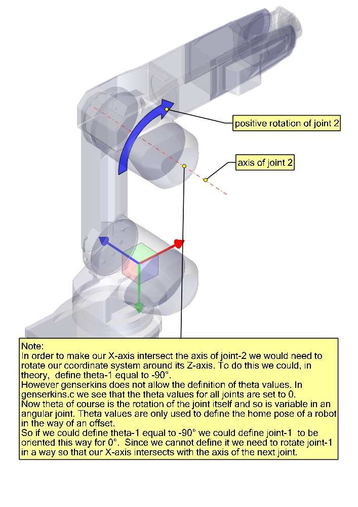
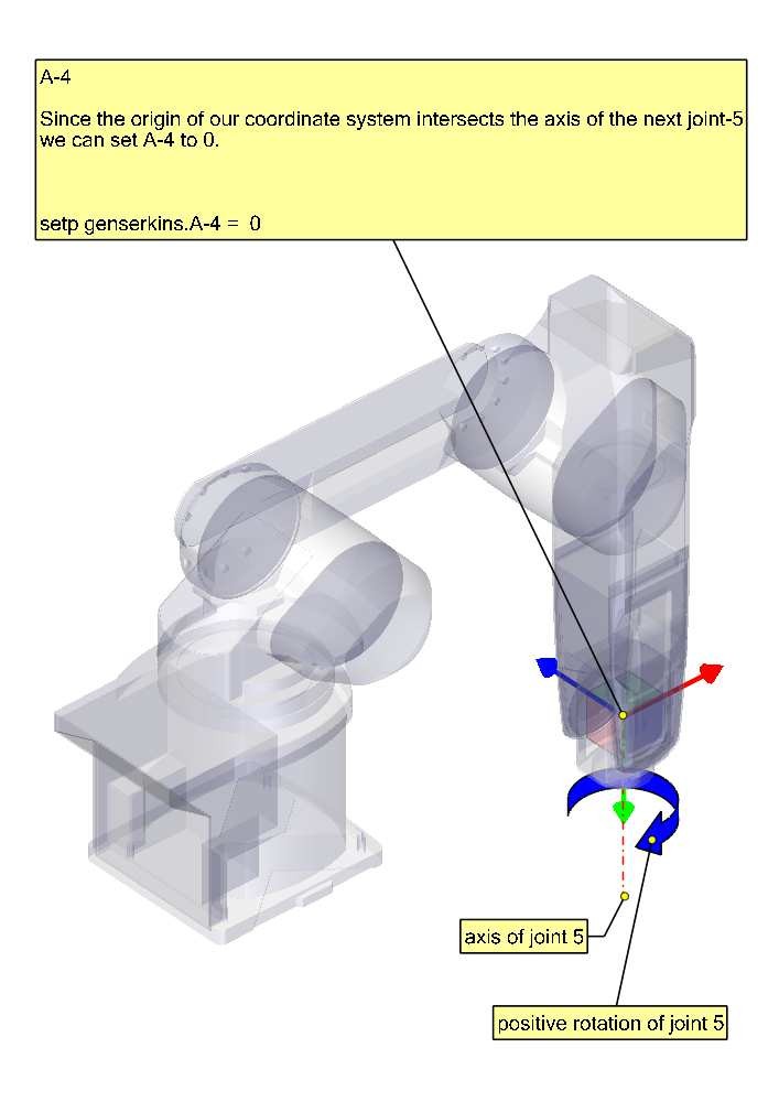
Note that genserkins does not handle offsets to theta-values — theta is the joint variable that is controlled by LinuxCNC. With the CS aligned with the joint, a rotation around its Z-Axis is identical to the rotation commanded to that joint by LinuxCNC. This makes it impossible to define the 0° position of our robots joints arbitrarily.
The three configurable parameters are:
-
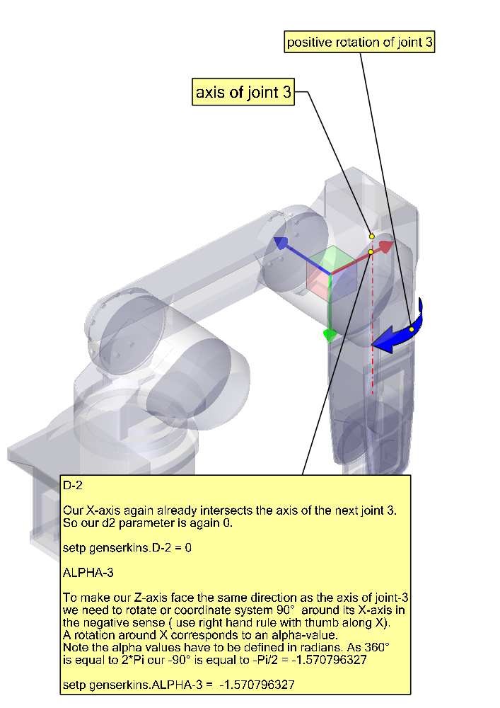
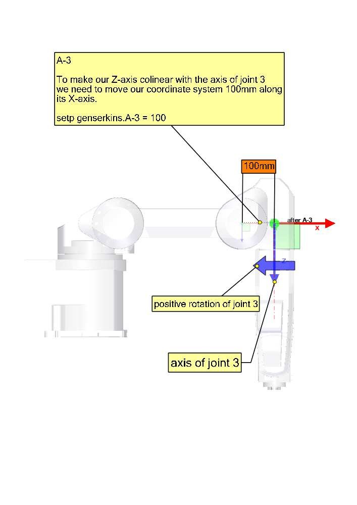
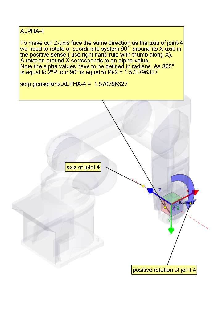
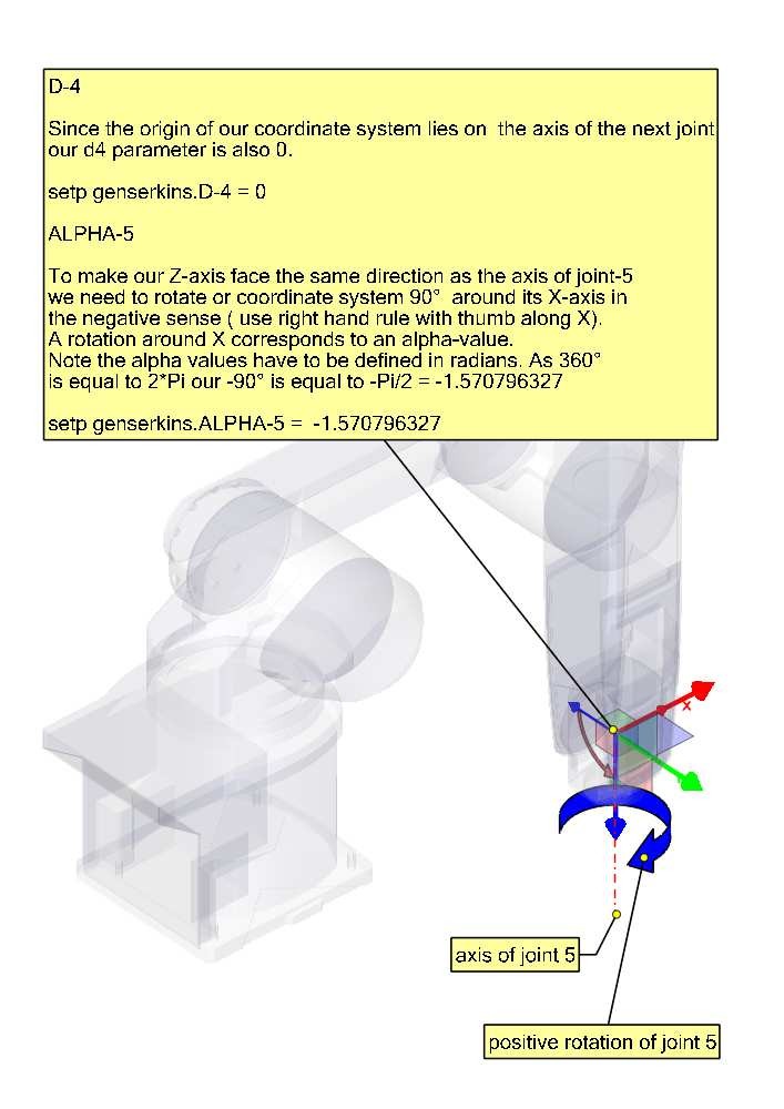
alpha : positive or negative rotation (in radians) around the X-axis of the "current coordinate system"
-
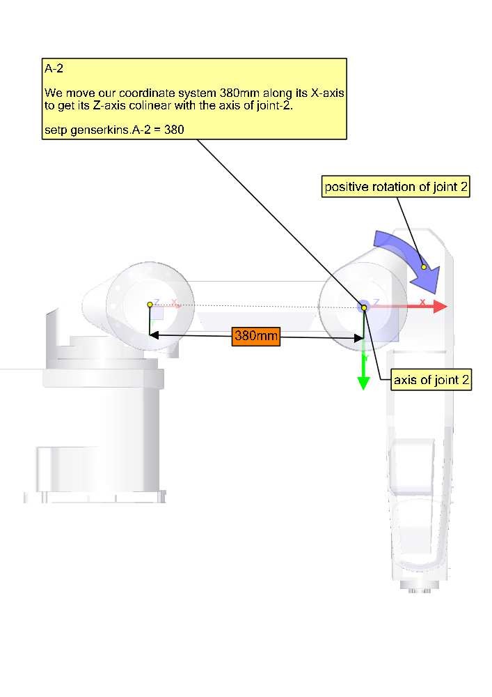
a : positive distance, along X, between two joint axes specified in machine units (mm or inch) defined in the system’s INI file.
-
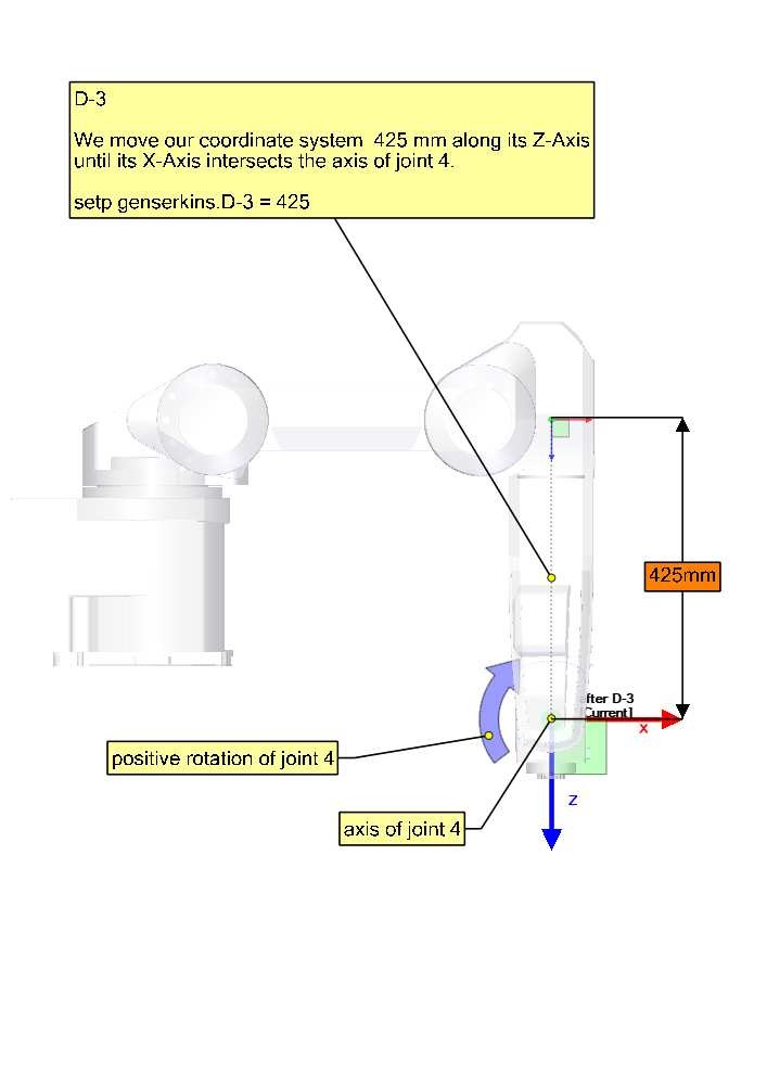
d : positive or negative length along Z (also in machine units)
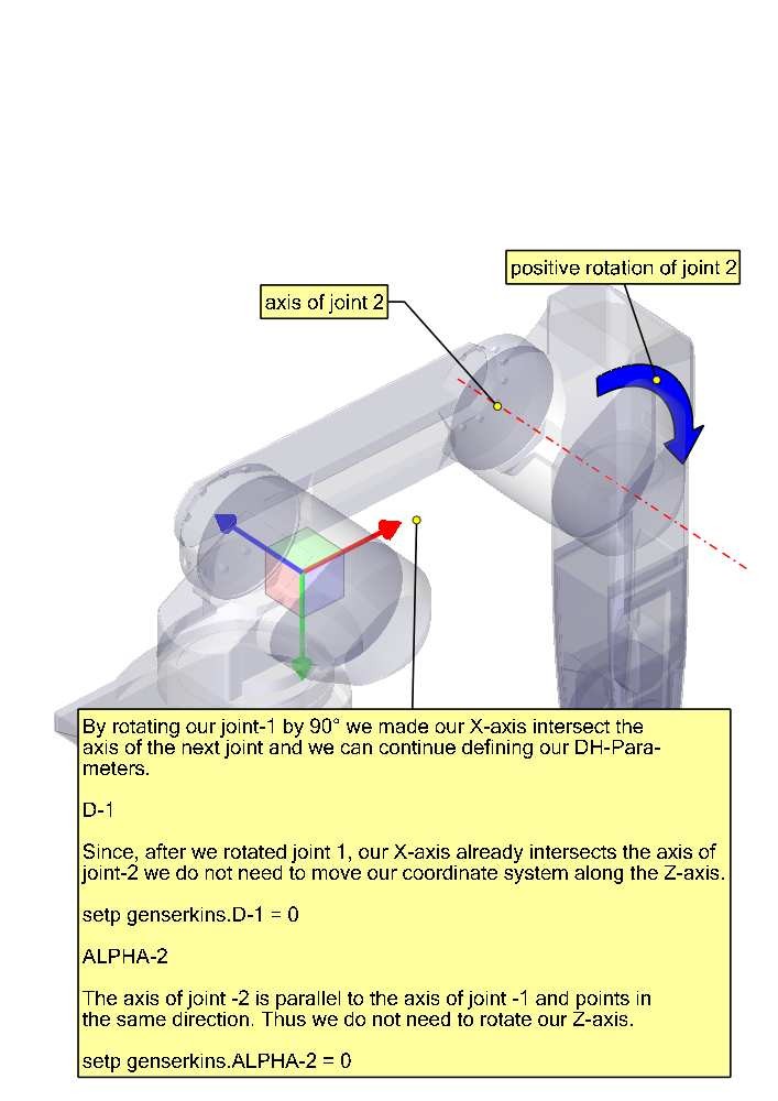
The parameter sets are always derived in the same order and a set is completed by setting the d-parameter. This does not leave the Z-axis of our CS aligned with the next joint! This may seem confusing but sticking to this rule will yield a working set of parameters. Once the d-parameter is set, the X-axis of our-CS needs to point to the axis of the next joint.
5. Numbering of joints and parameters
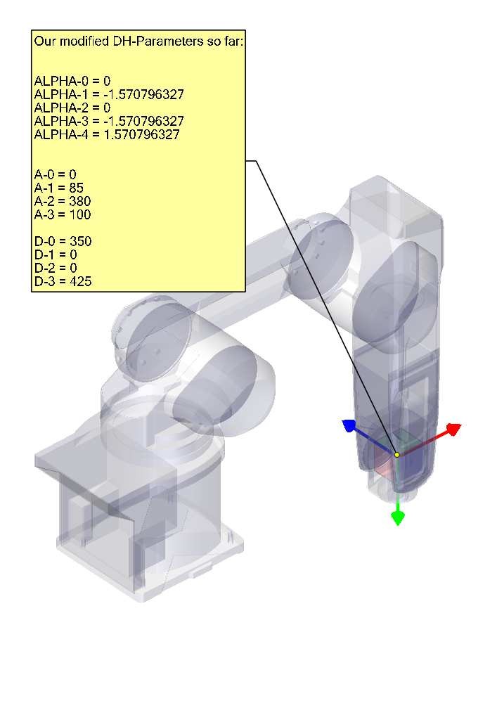
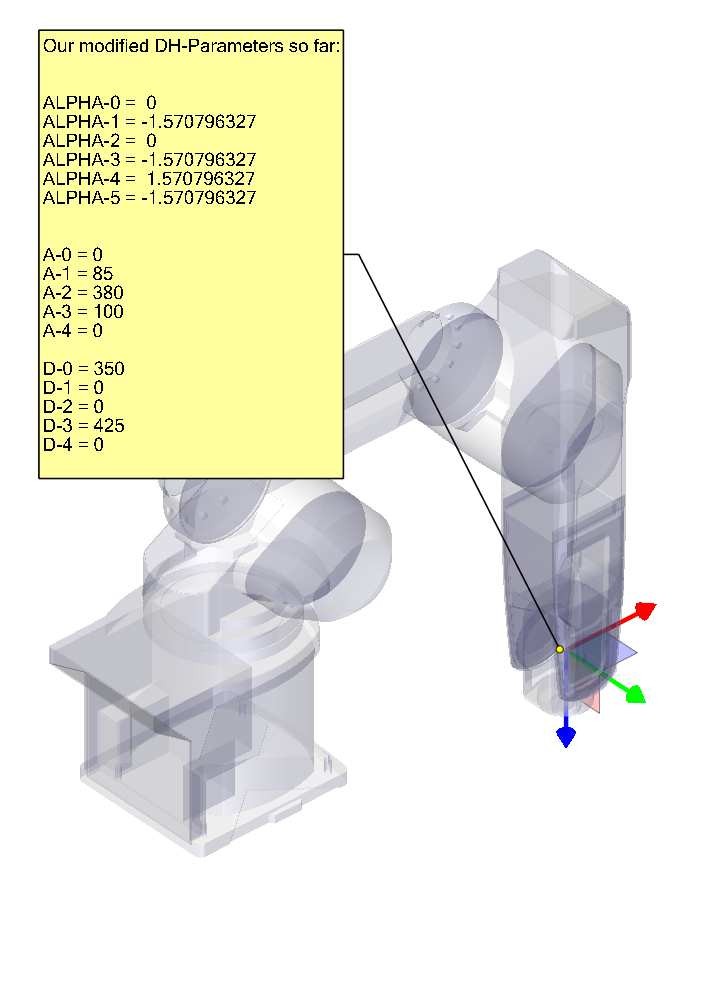
The first joint in LinuxCNC is joint-0 (because in software counting starts with 0) while most publications start with the number 1. That goes for all the parameters as well. That is, numbering starts with a-0, alpha-0, d-0 and ends with a-5, alpha-5 and d-5. Keep this in mind when following a publication to set up genserkins parameters.
6. How to start
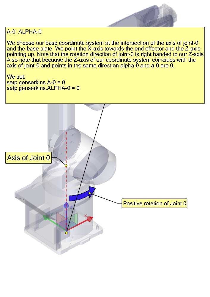
Convention is to start by placing the reference-CS in the base of the robot with it’s Z-axis coinciding with the axis of the first joint and its X-axis pointing toward the next joint’s axis.
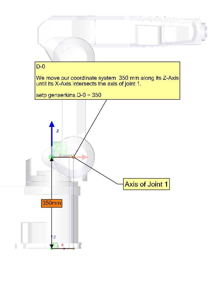
This will also result in the DRO values in LinuxCNC being referenced to that point. Having done so sets a-0 and alpha-0 to 0. The above mentioned publication (Craig) also sets d-0 to 0, which is confusing when a displacement offset is needed in order to have the reference-CS at the bottom of the base. Setting d-0 = to the displacement gives correct results. In this manner, the first set of parameters are alpha-0 = 0, a-0 = 0, d0 = displacement, and the X-axis of the CS points to the axis of the next joint (joint-1).
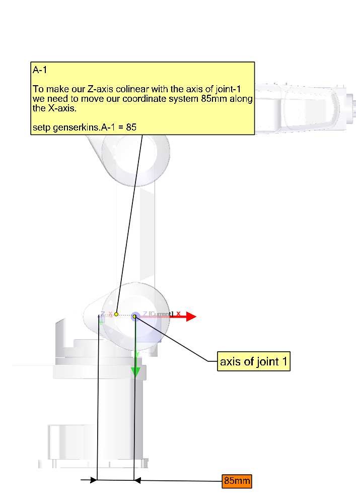
Derivation of the net set (alpha-1, a-1, d-1) follows — always using the same sequence all the way to the sixth set (alpha-5, a-5, d-5).
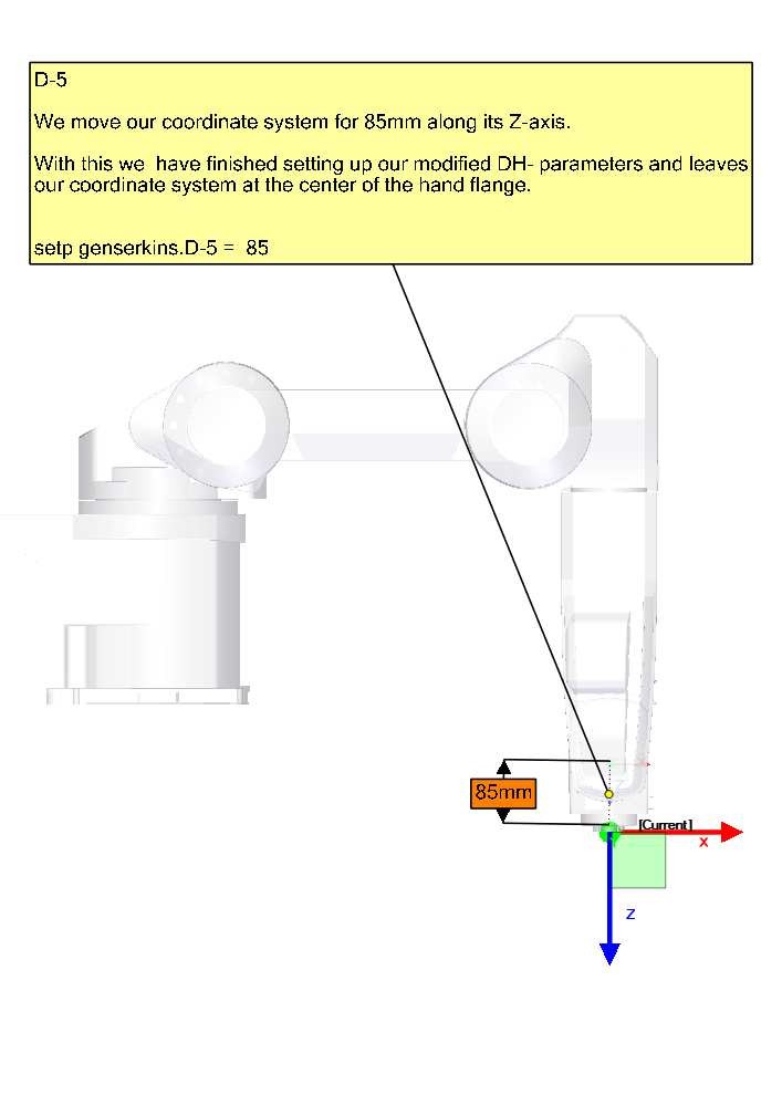
And thus, the TCP-CS of the end-effector is sitting in the center of the hand flange.
7. Special cases
If the next joint-axis is parallel to the last then one could arbitrarily choose a value for the d-parameter but there is no point in setting it other than 0.
8. Detailed Example (RV-6SL)
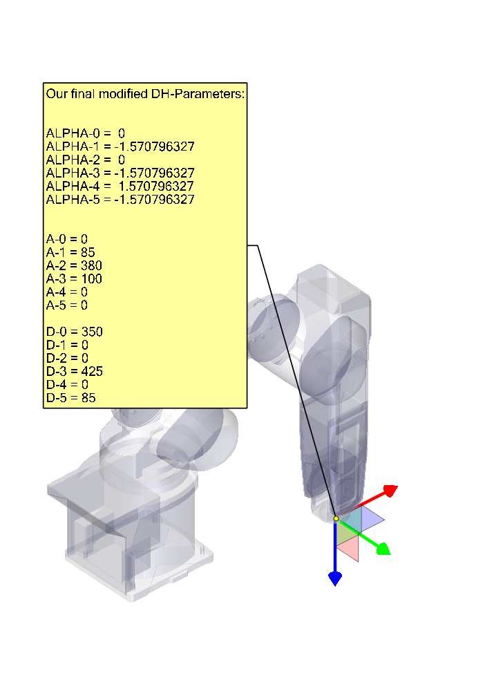
Described below is a method to derive the required "modified DH-parameters" for a Mitsubishi RV-6SDL and how to set the parameters in the HAL file to be used with the genserkins kinematics in LinuxCNC. The necessary dimensions are best taken from a dimensional drawing provided by the manufacturer of the robot.

9. Credits
Thanks to user Aciera for all text and the graphics for the RV-6SL robot!