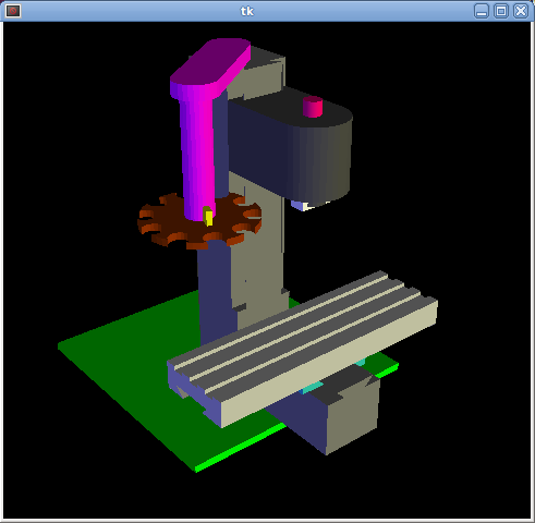
Vismach is a set of Python functions that can be used to create and animate models of machines. Vismach displays the model in a 3D viewport and the model parts are animated as the values of associated HAL pins change.
The Vismach viewport view can be manipulated as follows:
-
zoom by scroll wheel or right button drag,
-
pan by left button drag,
-
rotate by middle-button drag or shift-drag.
A Vismach model takes the form of a Python script and can use standard Python syntax. This means that there is more than one way to lay out the script, but in the examples given in this document I will use the simplest and most basic of them.
The basic sequence in creating the Vismach model is
-
Create the HAL pins that control the motion.
-
Create the parts.
-
Define how they move.
-
Assemble into movement groups.
1. Start the script
It is useful for testing to include the #!/usr/bin/env python3 to allow the file to be run as a script. The first thing to do is to import the required libraries.
#!/usr/bin/env python3

from vismach import *
import hal
import math
import sys
2. Create the HAL pins.
HAL pins are created with the normal Python "hal" library, and are not specific to Vismach. Further details can be found in the Creating Non-realtime Components in Python section. A component should be created with a name that matches the script file name and then the HAL pins are added to that component. They will be referenced by their component handle and short name when used to animate the Vismach model.
c = hal.component("samplegui")
c.newpin("joint0", hal.HAL_FLOAT, hal.HAL_IN)
c.newpin("joint1", hal.HAL_FLOAT, hal.HAL_IN)
c.ready()
Will create HAL pins samplegui.joint0 and samplegui.joint1. When loading the Vismach model with loadusr -W samplegui the c.ready() function tells loadusr it’s ready.
3. Creating Parts
It is probably easiest to create geometry in a CAD package and import
into the model script with the AsciiSTL() or AsciiOBJ() functions.
Both functions can take one of two named arguments, either a filename
or raw data:
-
part = AsciiSTL(filename="path/to/file.stl") +
  part = AsciiSTL(data="solid part1 facet normal ....") +
  part = AsciiOBJ(filename="path/to/file.obj") +
  part = AsciiOBJ(data="v 0.123 0.234 0.345 1.0 ...")
The parts will be created in the Vismach space in the same locations as they occupy in the STL or OBJ space. This means that it may be possible to assemble the model in the CAD package.
Alternatively parts can be created inside the model script from a range of shape primitives. Many shapes are created at the origin and need to be moved to the required location after creation:
-
cylinder = CylinderX(x1, r1, x2, r2) +
  cylinder = CylinderY(y1, r1, y2, r2) +
  cylinder = CylinderZ(z1, r1, z2, r2)
Creates a (optionally tapered) cylinder on the given axis with the given radii at the given points on the axis. -
sphere = Sphere(x, y, z, r)
Creates a sphere of radius r at (x,y,z) -
triangle = TriangleXY(x1, y1, x2, y2, x3, y3, z1, z2) +
  triangle = TriangleXZ(x1, z1, x2, z2, x3, z3, y1, y2) +
  triangle = TriangleYZ(y1, z1, y2, z2, y3, z3, x1, x2)
Creates a triangular plate between planes defined by the last two values parallel to the specified plane, with vertices given by the three coordinate pairs. -
arc = ArcX(x1, x2, r1, r2, a1, a2)
Create an arc shape. -
box = Box(x1, y1, z1, x2, y2, z2)
Creates a rectangular prism with opposite corners at the specified positions and edges parallel to the XYZ axes. -
box = BoxCentered(xw, yw, zw)
Creates an xw by yw by zw box centred on the origin. -
box = BoxCenteredXY(xw, yw, z)
Creates a box of width xw / yw and height z.
Composite parts may be created by assembling these primitives either
at creation time or subsequently using Collection():
part1 = Collection([Sphere(100,100,100,50), CylinderX(100,40,150,30)])
part2 = Box(50,40,75,100,75,100)
part3 = Collection([part2, TriangleXY(10,10,20,10,15,20,100,101)])
part4 = Collection([part1, part2])
4. Moving Parts
Parts may need to be moved in the Vismach space to assemble the model. They may also need to be moved to create the animation as the animation rotation axis is created at the origin (but moves with the Part):
-
part1 = Translate([part1], x, y, z)
Move part1 the specified distances in x, y and z. -
part1 = Rotate([part1], theta, x, y, z)
Rotate the part by angle theta about an axis between the origin and x, y, z.
5. Animating Parts
To animate the model (controlled by the values of HAL pins) there are two functions HalTranslate and HalRotate. For parts to move inside an assembly they need to have their HAL motions defined before being assembled with the "Collection" command. The rotation axis and translation vector move with the part as it is moved by the vismach script during model assembly, or as it moves in response to the HAL pins as the model is animated:
-
part = HalTranslate([part], comp, "hal_pin", xs, ys, zs)
The function arguments are:-
first a collection/part which can be pre-created earlier in the script, or could be created at this point if preferred eg
part1 = HalTranslate([Box(....)], ...). -
The HAL component is the next argument, i.e. the object returned by the
comp = hal.component(...)command. After that is the name of the HAL in that will animate the motion, this needs to match an existing HAL pin that is part of the HAL component created earlier in the script. -
Then follow the X, Y, Z scales.
For a Cartesian machine created at 1:1 scale this would typically be 1,0,0 for a motion in the positive X direction.
However if the STL file happened to be in cm and the machine was in inches, this could be fixed at this point by using 0.3937 (1cm /2.54in) as the scale.
-
-
part = HalRotate([part], comp, "hal_pin", angle_scale, x, y, z)
This command is similar in its operation to HalTranslate except that it is typically necessary to move the part to the origin first to define the axis.-
The axis of rotation is from the origin point to the point defined by (x,y,z).
When the part is moved back away from the origin to its correct location the axis of rotation can be considered to remain "embedded" in the part. -
Rotation angles are in degrees, so for a rotary joint with a 0-1 scaling you would need to use an angle scale of 360.
-
6. Assembling the model.
In order for parts to move together they need to be assembled with the Collection() command. It is important to assemble the parts and define their motions in the correct sequence. For example to create a moving head milling machine with a rotating spindle and an animated draw bar you would:
-
Create the head main body.
-
Create the spindle at the origin.
-
Define the rotation.
-
Move the head to the spindle or spindle to the head.
-
Create the draw bar.
-
Define the motion of the draw bar.
-
Assemble the three parts into a head assembly.
-
Define the motion of the head assembly.
In this example the spindle rotation is indicated by rotation of a set of drive dogs:
#Drive dogs
dogs = Box(-6,-3,94,6,3,100)
dogs = Color([1,1,1,1],[dogs])
dogs = HalRotate([dogs],c,"spindle",360,0,0,1)
dogs = Translate([dogs],-1,49,0)

#Drawbar
draw = CylinderZ(120,3,125,3)
draw = Color([1,0,.5,1],[draw])
draw = Translate([draw],-1,49,0)
draw = HalTranslate([draw],c,"drawbar",0,0,1)

# head/spindle
head = AsciiSTL(filename="./head.stl")
head = Color([0.3,0.3,0.3,1],[head])
head = Translate([head],0,0,4)
head = Collection([head, tool, dogs, draw])
head = HalTranslate([head],c,"Z",0,0,0.1)

# base
base = AsciiSTL(filename="./base.stl")
base = Color([0.5,0.5,0.5,1],[base])
# mount head on it
base = Collection([head, base])
Finally a single collection of all the machine parts, floor and work (if any) needs to be created:
-
For a serial machine each new part will be added to the collection of the previous part.
-
For a parallel machine there may be several "base" parts.
Thus, for example, in scaragui.py link3 is added to link2, link2 to link1 and link1 to link0, so the final model is created by:
model = Collection([link0, floor, table])
Whereas a VMC model with separate parts moving on the base might have:
model = Collection([base, saddle, head, carousel])
7. Other functions
-
part = Color([colorspec], [part])
Sets the display color of the part. Note that unlike the other functions the part definition comes second in this case.
The colorspec consists of the three RGB values and an opacity. For example [1,0,0,0.5] for a 50% opacity red. -
myhud = Hud()
Creates a heads-up display in the Vismach GUI to display such items as axis positions.
-
tooltip = Capture()
Think of this as an invisible part that needs to be attached to the tooltip to track the position and orientation of the tool coordinate system. It is actually a transformation matrix that is constantly updated as the model moves. -
work = Capture()
Same as above but attached to the work table to track the work coordinate system. -
main(model, tooltip, work, size=10, hud=0, rotation_vectors=None,
  lat=0, lon=0)
This is the command that makes it all happen, creates the display etc.-
model should be a collection that contains all the machine parts.
-
tooltip and work need to be created by
Capture(). Vismach needs this information to draw the backplot which is basically the tooltip position drawn in the work coordinate system.
Seescaragui.pyfor an example of how to connect the tool tip to a tool and the tool to the model. -
Either rotation_vectors or latitude/longitude can be used to set the original viewpoint and it is advisable to do as the default initial viewpoint is rather unhelpfully from immediately overhead.
-
size sets the extent of the volume visualized in the initial view.
-
hud refers to a head-up display of axis positions.
-
8. Basic structure of a Vismach script.
#imports
from vismach import *
import hal
#create the HAL component and pins
comp = hal.component("compname")
comp.newpin("pin_name", hal.HAL_FLOAT, hal.HAL_IN)
...
#create the floor, tool and work
floor = Box(-50, -50, -3, 50, 50, 0)
work = Capture()
tooltip = Capture()
...
#Build and assemble the model
part1 = Collection([Box(-6,-3,94,6,3,100)])
part1 = Color([1,1,1,1],[part1])
part1 = HalRotate([part1],comp,"pin_name",360,0,0,1)
part1 = Translate([dogs],-1,49,0)
...
#create a top-level model
model = Collection([base, saddle, head, carousel])
#Start the visualization
main(model, tooltip, work, 100, lat=-75, lon=215)