1. Intended audience
This document is a collection of notes about the internals of LinuxCNC. It is primarily of interest to developers, however much of the information here may also be of interest to system integrators and others who are simply curious about how LinuxCNC works. Much of this information is now outdated and has never been reviewed for accuracy.
2. Organization
There will be a chapter for each of the major components of LinuxCNC, as well as chapter(s) covering how they work together. This document is very much a work in progress, and its layout may change in the future.
3. Terms and definitions
-
AXIS - An axis is one of the nine degrees of freedom that define a tool position in three-dimensional Cartesian space. Those nine axes are referred to as X, Y, Z, A, B, C, U, V, and W. The linear orthagonal coordinates X, Y, and Z determine where the tip of the tool is positioned. The angular coordinates A, B, and C determine the tool orientation. A second set of linear orthagonal coordinates U, V, and W allows tool motion (typically for cutting actions) relative to the previously offset and rotated axes. Unfortunately “axis” is also sometimes used to mean a degree of freedom of the machine itself, such as the saddle, table, or quill of a Bridgeport type milling machine. On a Bridgeport this causes no confusion, since movement of the table directly corresponds to movement along the X axis. However, the shoulder and elbow joints of a robot arm and the linear actuators of a hexapod do not correspond to movement along any Cartesian axis, and in general it is important to make the distinction between the Cartesian axes and the machine degrees of freedom. In this document, the latter will be called joints, not axes. (The GUIs and some other parts of the code may not always follow this distinction, but the internals of the motion controller do.)
-
JOINT - A joint is one of the movable parts of the machine. Joints are distinct from axes, although the two terms are sometimes (mis)used to mean the same thing. In LinuxCNC, a joint is a physical thing that can be moved, not a coordinate in space. For example, the quill, knee, saddle, and table of a Bridgeport mill are all joints. The shoulder, elbow, and wrist of a robot arm are joints, as are the linear actuators of a hexapod. Every joint has a motor or actuator of some type associated with it. Joints do not necessarily correspond to the X, Y, and Z axes, although for machines with trivial kinematics that may be the case. Even on those machines, joint position and axis position are fundamentally different things. In this document, the terms joint and axis are used carefully to respect their distinct meanings. Unfortunately that isn’t necessarily true everywhere else. In particular, GUIs for machines with trivial kinematics may gloss over or completely hide the distinction between joints and axes. In addition, the ini file uses the term axis for data that would more accurately be described as joint data, such as input and output scaling, etc.
-
POSE - A pose is a fully specified position in 3-D Cartesian space. In the LinuxCNC motion controller, when we refer to a pose we mean an EmcPose structure, containing six linear coordinates (X, Y, Z, U, V, and W) and three angular ones (A, B, and C).
4. Architecture overview
There are four components contained in the LinuxCNC Architecture: a motion controller (EMCMOT), a discrete IO controller (EMCIO), a task executor which coordinates them (EMCTASK) and several text-mode and graphical User Interfaces. Each of them will be described in the current document, both from the design point of view and from the developers point of view (where to find needed data, how to easily extend/modify things, etc.).
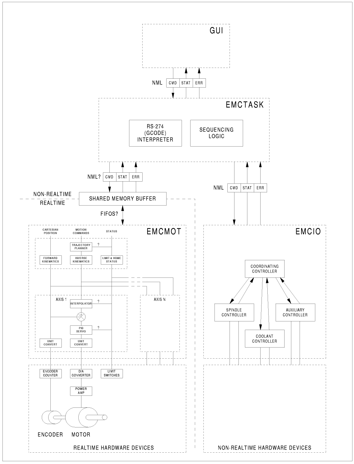
LinuxCNC software architecture. At the coarsest level, LinuxCNC is a hierarchy of three controllers: the task level command handler and program interpreter, the motion controller, and the discrete I/O controller. The discrete I/O controller is implemented as a hierarchy of controllers, in this case for spindle, coolant, and auxiliary (e.g., estop, lube) subsystems. The task controller coordinates the actions of the motion and discrete I/O controllers. Their actions are programmed in conventional numerical control "G and M code" programs, which are interpreted by the task controller into NML messages and sent to either the motion or discrete I/O controllers at the appropriate times.
5. Motion Controller Introduction
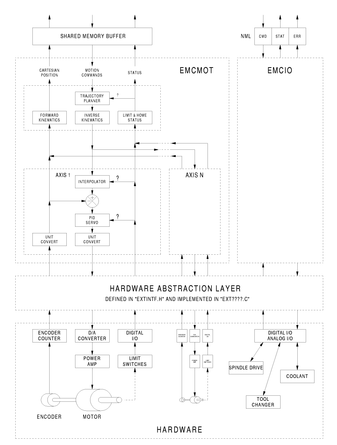
The motion controller receives commands from user space modules via a shared memory buffer, and executes those commands in realtime. The status of the controller is made available to the user space modules through the same shared memory area. The motion controller interacts with the motors and other hardware using the HAL (Hardware Abstraction Layer). This document assumes that the reader has a basic understanding of the HAL, and uses terms like HAL pins, HAL signals, etc, without explaining them. For more information about the HAL, see the HAL Manual. Another chapter of this document will eventually go into the internals of the HAL itself, but in this chapter, we only use the HAL API as defined in src/hal/hal.h.
6. Block diagrams and Data Flow
The following figure is a block diagram of a joint controller. There is one joint controller per joint. The joint controllers work at a lower level than the kinematics, a level where all joints are completely independent. All the data for a joint is in a single joint structure. Some members of that structure are visible in the block diagram, such as coarse_pos, pos_cmd, and motor_pos_fb.
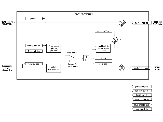
The above figure shows five of the seven sets of position information that form the main data flow through the motion controller. The seven forms of position data are as follows:
-
emcmotStatus->carte_pos_cmd - This is the desired position, in Cartesian coordinates. It is updated at the traj rate, not the servo rate. In coord mode, it is determined by the traj planner. In teleop mode, it is determined by the traj planner? In free mode, it is either copied from actualPos, or generated by applying forward kins to (2) or (3).
-
emcmotStatus->joints[n].coarse_pos - This is the desired position, in joint coordinates, but before interpolation. It is updated at the traj rate, not the servo rate. In coord mode, it is generated by applying inverse kins to (1) In teleop mode, it is generated by applying inverse kins to (1) In free mode, it is copied from (3), I think.
-
'emcmotStatus->joints[n].pos_cmd - This is the desired position, in joint coords, after interpolation. A new set of these coords is generated every servo period. In coord mode, it is generated from (2) by the interpolator. In teleop mode, it is generated from (2) by the interpolator. In free mode, it is generated by the free mode traj planner.
-
emcmotStatus->joints[n].motor_pos_cmd - This is the desired position, in motor coords. Motor coords are generated by adding backlash compensation, lead screw error compensation, and offset (for homing) to (3). It is generated the same way regardless of the mode, and is the output to the PID loop or other position loop.
-
emcmotStatus->joints[n].motor_pos_fb - This is the actual position, in motor coords. It is the input from encoders or other feedback device (or from virtual encoders on open loop machines). It is "generated" by reading the feedback device.
-
emcmotStatus->joints[n].pos_fb - This is the actual position, in joint coordinates. It is generated by subtracting offset, lead screw error compensation, and backlash compensation from (5). It is generated the same way regardless of the operating mode.
-
emcmotStatus->carte_pos_fb - This is the actual position, in Cartesian coordinates. It is updated at the traj rate, not the servo rate. Ideally, actualPos would always be calculated by applying forward kinematics to (6). However, forward kinematics may not be available, or they may be unusable because one or more axes aren’t homed. In that case, the options are: A) fake it by copying (1), or B) admit that we don’t really know the Cartesian coordinates, and simply don’t update actualPos. Whatever approach is used, I can see no reason not to do it the same way regardless of the operating mode. I would propose the following: If there are forward kins, use them, unless they don’t work because of unhomed axes or other problems, in which case do (B). If no forward kins, do (A), since otherwise actualPos would never get updated.
7. Homing
7.1. Homing state diagram

7.2. Another homing diagram

8. Commands
This section simply lists all of the commands that can be sent to the motion module, along with detailed explanations of what they do. The command names are defined in a large typedef enum in code, each command name starts with EMCMOT_, which is omitted here.)
The commands are implemented by a large switch statement in the function emcmotCommandHandler(), which is called at the servo rate. More on that function later.
There are approximately 44 commands - this list is still under construction.
8.1. ABORT
The ABORT command simply stops all motion. It can be issued at any
time, and will always be accepted. It does not disable the motion
controller or change any state information, it simply cancels any
motion that is currently in progress.
[It seems that the
higher level code (TASK and above) also use ABORT to clear faults.
Whenever there is a persistent fault (such as being outside the
hardware limit switches), the higher level code sends a constant
stream of ABORTs to the motion controller trying to make the
fault go away. Thousands of 'em…. That means that the motion
controller should avoid persistent faults. This needs to be looked
into.]
8.1.1. Requirements
None. The command is always accepted and acted on immediately.
8.1.2. Results
In free mode, the free mode trajectory planners are disabled. That results in each joint stopping as fast as its accel (decel) limit allows. The stop is not coordinated. In teleop mode, the commanded Cartesian velocity is set to zero. I don’t know exactly what kind of stop results (coordinated, uncoordinated, etc), but will figure it out eventually. In coord mode, the coord mode trajectory planner is told to abort the current move. Again, I don’t know the exact result of this, but will document it when I figure it out.
8.2. FREE
The FREE command puts the motion controller in free mode. Free mode means that each joint is independent of all the other joints. Cartesian coordinates, poses, and kinematics are ignored when in free mode. In essence, each joint has its own simple trajectory planner, and each joint completely ignores the other joints. Some commands (like Joint JOG and HOME) only work in free mode. Other commands, including anything that deals with Cartesian coordinates, do not work at all in free mode.
8.2.1. Requirements
The command handler applies no requirements to the FREE command, it will always be accepted. However, if any joint is in motion (GET_MOTION_INPOS_FLAG() == FALSE), then the command will be ignored. This behavior is controlled by code that is now located in the function set_operating_mode() in control.c, that code needs to be cleaned up. I believe the command should not be silently ignored, instead the command handler should determine whether it can be executed and return an error if it cannot.
8.2.2. Results
If the machine is already in free mode, nothing. Otherwise, the machine is placed in free mode. Each joint’s free mode trajectory planner is initialized to the current location of the joint, but the planners are not enabled and the joints are stationary.
8.3. TELEOP
The TELEOP command places the machine in teleoperating mode. In teleop mode, movement of the machine is based on Cartesian coordinates using kinematics, rather than on individual joints as in free mode. However the trajectory planner per se is not used, instead movement is controlled by a velocity vector. Movement in teleop mode is much like jogging, except that it is done in Cartesian space instead of joint space. On a machine with trivial kinematics, there is little difference between teleop mode and free mode, and GUIs for those machines might never even issue this command. However for non-trivial machines like robots and hexapods, teleop mode is used for most user commanded jog type movements.
8.3.1. Requirements
The command handler will reject the TELEOP command with an error message if the kinematics cannot be activated because the one or more joints have not been homed. In addition, if any joint is in motion (GET_MOTION_INPOS_FLAG() == FALSE), then the command will be ignored (with no error message). This behavior is controlled by code that is now located in the function set_operating_mode() in control.c. I believe the command should not be silently ignored, instead the command handler should determine whether it can be executed and return an error if it cannot.
8.3.2. Results
If the machine is already in teleop mode, nothing. Otherwise the machine is placed in teleop mode. The kinematics code is activated, interpolators are drained and flushed, and the Cartesian velocity commands are set to zero.
8.4. COORD
The COORD command places the machine in coordinated mode. In coord mode, movement of the machine is based on Cartesian coordinates using kinematics, rather than on individual joints as in free mode. In addition, the main trajectory planner is used to generate motion, based on queued LINE, CIRCLE, and/or PROBE commands. Coord mode is the mode that is used when executing a G-code program.
8.4.1. Requirements
The command handler will reject the COORD command with an error message if the kinematics cannot be activated because the one or more joints have not been homed. In addition, if any joint is in motion (GET_MOTION_INPOS_FLAG() == FALSE), then the command will be ignored (with no error message). This behavior is controlled by code that is now located in the function set_operating_mode() in control.c. I believe the command should not be silently ignored, instead the command handler should determine whether it can be executed and return an error if it cannot.
8.4.2. Results
If the machine is already in coord mode, nothing. Otherwise, the machine is placed in coord mode. The kinematics code is activated, interpolators are drained and flushed, and the trajectory planner queues are empty. The trajectory planner is active and awaiting a LINE, CIRCLE, or PROBE command.
8.5. ENABLE
The ENABLE command enables the motion controller.
8.5.1. Requirements
None. The command can be issued at any time, and will always be accepted.
8.5.2. Results
If the controller is already enabled, nothing. If not, the controller is enabled. Queues and interpolators are flushed. Any movement or homing operations are terminated. The amp-enable outputs associated with active joints are turned on. If forward kinematics are not available, the machine is switched to free mode.
8.6. DISABLE
The DISABLE command disables the motion controller.
8.6.1. Requirements
None. The command can be issued at any time, and will always be accepted.
8.6.2. Results
If the controller is already disabled, nothing. If not, the controller is disabled. Queues and interpolators are flushed. Any movement or homing operations are terminated. The amp-enable outputs associated with active joints are turned off. If forward kinematics are not available, the machine is switched to free mode.
8.7. ENABLE_AMPLIFIER
The ENABLE_AMPLIFIER command turns on the amp enable output for a single output amplifier, without changing anything else. Can be used to enable a spindle speed controller.
8.7.1. Requirements
None. The command can be issued at any time, and will always be accepted.
8.7.2. Results
Currently, nothing. (A call to the old extAmpEnable function is currently commented out.) Eventually it will set the amp enable HAL pin true.
8.8. DISABLE_AMPLIFIER
The DISABLE_AMPLIFIER command turns off the amp enable output for a single amplifier, without changing anything else. Again, useful for spindle speed controllers.
8.8.1. Requirements
None. The command can be issued at any time, and will always be accepted.
8.8.2. Results
Currently, nothing. (A call to the old extAmpEnable function is currently commented out.) Eventually it will set the amp enable HAL pin false.
8.9. ACTIVATE_JOINT
The ACTIVATE_JOINT command turns on all the calculations associated with a single joint, but does not change the joint’s amp enable output pin.
8.9.1. Requirements
None. The command can be issued at any time, and will always be accepted.
8.9.2. Results
Calculations for the specified joint are enabled. The amp enable pin is not changed, however, any subsequent ENABLE or DISABLE commands will modify the joint’s amp enable pin.
8.10. DEACTIVATE_JOINT
The DEACTIVATE_JOINT command turns off all the calculations associated with a single joint, but does not change the joint’s amp enable output pin.
8.10.1. Requirements
None. The command can be issued at any time, and will always be accepted.
8.10.2. Results
Calculations for the specified joint are enabled. The amp enable pin is not changed, and subsequent ENABLE or DISABLE commands will not modify the joint’s amp enable pin.
8.11. ENABLE_WATCHDOG
The ENABLE_WATCHDOG command enables a hardware based watchdog (if present).
8.11.1. Requirements
None. The command can be issued at any time, and will always be accepted.
8.11.2. Results
Currently nothing. The old watchdog was a strange thing that used a specific sound card. A new watchdog interface may be designed in the future.
8.12. DISABLE_WATCHDOG
The DISABLE_WATCHDOG command disables a hardware based watchdog (if present).
8.12.1. Requirements
None. The command can be issued at any time, and will always be accepted.
8.12.2. Results
Currently nothing. The old watchdog was a strange thing that used a specific sound card. A new watchdog interface may be designed in the future.
8.13. PAUSE
The PAUSE command stops the trajectory planner. It has no effect in free or teleop mode. At this point I don’t know if it pauses all motion immediately, or if it completes the current move and then pauses before pulling another move from the queue.
8.13.1. Requirements
None. The command can be issued at any time, and will always be accepted.
8.13.2. Results
The trajectory planner pauses.
8.14. RESUME
The RESUME command restarts the trajectory planner if it is paused. It has no effect in free or teleop mode, or if the planner is not paused.
8.14.1. Requirements
None. The command can be issued at any time, and will always be accepted.
8.14.2. Results
The trajectory planner resumes.
8.15. STEP
The STEP command restarts the trajectory planner if it is paused, and tells the planner to stop again when it reaches a specific point. It has no effect in free or teleop mode. At this point I don’t know exactly how this works. I’ll add more documentation here when I dig deeper into the trajectory planner.
8.15.1. Requirements
None. The command can be issued at any time, and will always be accepted.
8.15.2. Results
The trajectory planner resumes, and later pauses when it reaches a specific point.
8.16. SCALE
The SCALE command scales all velocity limits and commands by a specified amount. It is used to implement feed rate override and other similar functions. The scaling works in free, teleop, and coord modes, and affects everything, including homing velocities, etc. However, individual joint velocity limits are unaffected.
8.16.1. Requirements
None. The command can be issued at any time, and will always be accepted.
8.16.2. Results
All velocity commands are scaled by the specified constant.
8.17. OVERRIDE_LIMITS
The OVERRIDE_LIMITS command prevents limits from tripping until the end of the next JOG command. It is normally used to allow a machine to be jogged off of a limit switch after tripping. (The command can actually be used to override limits, or to cancel a previous override.)
8.17.1. Requirements
None. The command can be issued at any time, and will always be accepted. (I think it should only work in free mode.)
8.17.2. Results
Limits on all joints are over-ridden until the end of the next JOG command. (This is currently broken… once an OVERRIDE_LIMITS command is received, limits are ignored until another OVERRIDE_LIMITS command re-enables them.)
8.18. HOME
The HOME command initiates a homing sequence on a specified joint. The actual homing sequence is determined by a number of configuration parameters, and can range from simply setting the current position to zero, to a multi-stage search for a home switch and index pulse, followed by a move to an arbitrary home location. For more information about the homing sequence, see the homing section of the Integrator Manual.
8.18.1. Requirements
The command will be ignored silently unless the machine is in free mode.
8.18.2. Results
Any jog or other joint motion is aborted, and the homing sequence starts.
8.19. JOG_CONT
The JOG_CONT command initiates a continuous jog on a single joint. A continuous jog is generated by setting the free mode trajectory planner’s target position to a point beyond the end of the joint’s range of travel. This ensures that the planner will move constantly until it is stopped by either the joint limits or an ABORT command. Normally, a GUI sends a JOG_CONT command when the user presses a jog button, and ABORT when the button is released.
8.19.1. Requirements
The command handler will reject the JOG_CONT command with an error message if machine is not in free mode, or if any joint is in motion (GET_MOTION_INPOS_FLAG() == FALSE), or if motion is not enabled. It will also silently ignore the command if the joint is already at or beyond its limit and the commanded jog would make it worse.
8.19.2. Results
The free mode trajectory planner for the joint identified by emcmotCommand->axis is activated, with a target position beyond the end of joint travel, and a velocity limit of emcmotCommand->vel. This starts the joint moving, and the move will continue until stopped by an ABORT command or by hitting a limit. The free mode planner accelerates at the joint accel limit at the beginning of the move, and will decelerate at the joint accel limit when it stops.
8.20. JOG_INCR
The JOG_INCR command initiates an incremental jog on a single joint. Incremental jogs are cumulative, in other words, issuing two JOG_INCR commands that each ask for 0.100 inches of movement will result in 0.200 inches of travel, even if the second command is issued before the first one finishes. Normally incremental jogs stop when they have traveled the desired distance, however they also stop when they hit a limit, or on an ABORT command.
8.20.1. Requirements
The command handler will silently reject the JOG_INCR command if machine is not in free mode, or if any joint is in motion (GET_MOTION_INPOS_FLAG() == FALSE), or if motion is not enabled. It will also silently ignore the command if the joint is already at or beyond its limit and the commanded jog would make it worse.
8.20.2. Results
The free mode trajectory planner for the joint identified by emcmotCommand->axis is activated, the target position is incremented/decremented by emcmotCommand->offset, and the velocity limit is set to emcmotCommand->vel. The free mode trajectory planner will generate a smooth trapezoidal move from the present position to the target position. The planner can correctly handle changes in the target position that happen while the move is in progress, so multiple JOG_INCR commands can be issued in quick succession. The free mode planner accelerates at the joint accel limit at the beginning of the move, and will decelerate at the joint accel limit to stop at the target position.
8.21. JOG_ABS
The JOG_ABS command initiates an absolute jog on a single joint. An absolute jog is a simple move to a specific location, in joint coordinates. Normally absolute jogs stop when they reach the desired location, however they also stop when they hit a limit, or on an ABORT command.
8.21.1. Requirements
The command handler will silently reject the JOG_ABS command if machine is not in free mode, or if any joint is in motion (GET_MOTION_INPOS_FLAG() == FALSE), or if motion is not enabled. It will also silently ignore the command if the joint is already at or beyond its limit and the commanded jog would make it worse.
8.21.2. Results
The free mode trajectory planner for the joint identified by emcmotCommand->axis is activated, the target position is set to emcmotCommand->offset, and the velocity limit is set to emcmotCommand->vel. The free mode trajectory planner will generate a smooth trapezoidal move from the present position to the target position. The planner can correctly handle changes in the target position that happen while the move is in progress. If multiple JOG_ABS commands are issued in quick succession, each new command changes the target position and the machine goes to the final commanded position. The free mode planner accelerates at the joint accel limit at the beginning of the move, and will decelerate at the joint accel limit to stop at the target position.
8.22. SET_LINE
The SET_LINE command adds a straight line to the trajectory planner queue.
(More later)
8.23. SET_CIRCLE
The SET_CIRCLE command adds a circular move to the trajectory planner queue.
(More later)
8.24. SET_TELEOP_VECTOR
The SET_TELEOP_VECTOR command instructs the motion controller to move along a specific vector in Cartesian space.
(More later)
8.25. PROBE
The PROBE command instructs the motion controller to move toward a specific point in Cartesian space, stopping and recording its position if the probe input is triggered.
(More later)
8.26. CLEAR_PROBE_FLAG
The CLEAR_PROBE_FLAG command is used to reset the probe input in preparation for a PROBE command. (Question: why shouldn’t the PROBE command automatically reset the input?)
(More later)
8.27. SET_xix
There are approximately 15 SET_xxx commands, where xxx is the name of some configuration parameter. It is anticipated that there will be several more SET commands as more parameters are added. I would like to find a cleaner way of setting and reading configuration parameters. The existing methods require many lines of code to be added to multiple files each time a parameter is added. Much of that code is identical or nearly identical for every parameter.
9. Backlash and Screw Error Compensation
+10. Task controller (EMCTASK)
10.1. State
Task has three possible internal states: E-stop, E-stop Reset, and Machine On.

11. IO controller (EMCIO)
The I/O Controller is separate module that accepts NML commands from TASK.
It interacts with external I/O using HAL pins.
iocontrol.cc is loaded via the linuxcnc script before TASK is.
There are curently two versions of iocontrol. The second version handles toolchange hardware errors
Curently ESTOP/Enable, coolant, lube, and tool changing are handled by
iocontrol. These are relatively low speed events, high speed coordinated I/O is handled in motion.
emctaskmain.cc sends I/O commands via taskclass.cc
Taskclass’s functions send NML messages out to iocontrol.cc
taskclass either uses the commands defined in c++ in it’s file or,
if defined, runs python based commands defined in files provided by the user.
iocontrol main loop process:
-
registers for SIGTERM and SIGINT signals from the OS.
-
checks to see it HAL inputs have changed
-
checks if read_tool_inputs() indicates the tool change is finished and set emcioStatus.status
-
checks for I/O related NML messages
nml message numbers: from emc.hh:
#define EMC_IO_INIT_TYPE ((NMLTYPE) 1601)
#define EMC_TOOL_STAT_TYPE ((NMLTYPE) 1199)
#define EMC_TOOL_INIT_TYPE ((NMLTYPE) 1101)
#define EMC_TOOL_HALT_TYPE ((NMLTYPE) 1102)
#define EMC_TOOL_ABORT_TYPE ((NMLTYPE) 1103)
#define EMC_TOOL_PREPARE_TYPE ((NMLTYPE) 1104)
#define EMC_TOOL_LOAD_TYPE ((NMLTYPE) 1105)
#define EMC_TOOL_UNLOAD_TYPE ((NMLTYPE) 1106)
#define EMC_TOOL_LOAD_TOOL_TABLE_TYPE ((NMLTYPE) 1107)
#define EMC_TOOL_SET_OFFSET_TYPE ((NMLTYPE) 1108)
#define EMC_TOOL_SET_NUMBER_TYPE ((NMLTYPE) 1109)
#define EMC_TOOL_START_CHANGE_TYPE ((NMLTYPE) 1110)
12. User Interfaces
+13. libnml Introduction
libnml is derived from the NIST rcslib without all the multi-platform support. Many of the wrappers around platform specific code has been removed along with much of the code that is not required by LinuxCNC. It is hoped that sufficient compatibility remains with rcslib so that applications can be implemented on non-Linux platforms and still be able to communicate with LinuxCNC.
This chapter is not intended to be a definitive guide to using libnml (or rcslib), instead, it will eventually provide an overview of each C++ class and their member functions. Initially, most of these notes will be random comments added as the code scrutinized and modified.
14. LinkedList
Base class to maintain a linked list. This is one of the core building blocks used in passing NML messages and assorted internal data structures.
15. LinkedListNode
Base class for producing a linked list - Purpose, to hold pointers to the previous and next nodes, pointer to the data, and the size of the data.
No memory for data storage is allocated.
16. SharedMemory
Provides a block of shared memory along with a semaphore (inherited from the Semaphore class). Creation and destruction of the semaphore is handled by the SharedMemory constructor and destructor.
17. ShmBuffer
Class for passing NML messages between local processes using a shared memory buffer. Much of internal workings are inherited from the CMS class.
18. Timer
The Timer class provides a periodic timer limited only by the resolution of the system clock. If, for example, a process needs to be run every 5 seconds regardless of the time taken to run the process, the following code snippet demonstrates how :
main()
{
    timer = new Timer(5.0);    /* Initialize a timer with a 5 second loop */
    while(0) {
        /* Do some process */
        timer.wait();    /* Wait till the next 5 second interval */
    }
    delete timer;
}
19. Semaphore
The Semaphore class provides a method of mutual exclusions for accessing a shared resource. The function to get a semaphore can either block until access is available, return after a timeout, or return immediately with or without gaining the semaphore. The constructor will create a semaphore or attach to an existing one if the ID is already in use.
The Semaphore::destroy() must be called by the last process only.
20. CMS
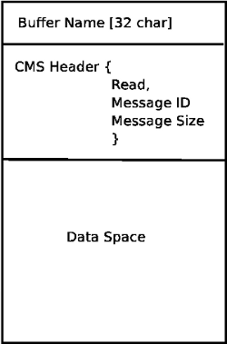
At the heart of libnml is the CMS class, it contains most of the functions used by libnml and ultimately NML. Many of the internal functions are overloaded to allow for specific hardware dependent methods of data passing. Ultimately, everything revolves around a central block of memory (referred to as the message buffer or just buffer). This buffer may exist as a shared memory block accessed by other CMS/NML processes, or a local and private buffer for data being transferred by network or serial interfaces.
The buffer is dynamically allocated at run time to allow for greater flexibility of the CMS/NML sub-system. The buffer size must be large enough to accommodate the largest message, a small amount for internal use and allow for the message to be encoded if this option is chosen (encoded data will be covered later). The following figure is an internal view of the buffer space.
The CMS base class is primarily responsible for creating the communications pathways and interfacing to the O.S.
21. Configuration file format
NML configuration consists of two types of line formats. One for Buffers, and a second for Processes that connect to the buffers.
21.1. Buffer line
The original NIST format of the buffer line is:
-
B name type host size neut RPC# buffer# max_procs key [type specific configs]
-
B - identifies this line as a Buffer configuration.
-
name - is the identifier of the buffer.
-
type - describes the buffer type - SHMEM, LOCMEM, FILEMEM, PHANTOM, or GLOBMEM.
-
host - is either an IP address or host name for the NML server
-
size - is the size of the buffer
-
neut - a boolean to indicate if the data in the buffer is encoded in a machine independent format, or raw.
-
RPC# - Obsolete - Place holder retained for backward compatibility only.
-
buffer# - A unique ID number used if a server controls multiple buffers.
-
max_procs - is the maximum processes allowed to connect to this buffer.
-
key - is a numerical identifier for a shared memory buffer
21.2. Type specific configs
The buffer type implies additional configuration options whilst the host operating system precludes certain combinations. In an attempt to distill published documentation in to a coherent format, only the SHMEM buffer type will be covered.
-
mutex=os_sem - default mode for providing semaphore locking of the buffer memory.
-
mutex=none - Not used
-
mutex=no_interrupts - not applicable on a Linux system
-
mutex=no_switching - not applicable on a Linux system
-
mutex=mao split - Splits the buffer in to half (or more) and allows one process to access part of the buffer whilst a second process is writing to another part.
-
TCP=(port number) - Specifies which network port to use.
-
UDP=(port number) - ditto
-
STCP=(port number) - ditto
-
serialPortDevName=(serial port) - Undocumented.
-
passwd=file_name.pwd - Adds a layer of security to the buffer by requiring each process to provide a password.
-
bsem - NIST documentation implies a key for a blocking semaphore, and if bsem=-1, blocking reads are prevented.
-
queue - Enables queued message passing.
-
ascii - Encode messages in a plain text format
-
disp - Encode messages in a format suitable for display (???)
-
xdr - Encode messages in External Data Representation. (see rpc/xdr.h for details).
-
diag - Enables diagnostics stored in the buffer (timings and byte counts ?)
21.3. Process line
The original NIST format of the process line is:
P name buffer type host ops server timeout master c_num [type specific configs]
-
P - identifies this line as a Process configuration.
-
name - is the identifier of the process.
-
buffer - is one of the buffers defined elsewhere in the config file.
-
type - defines whether this process is local or remote relative to the buffer.
-
host - specifies where on the network this process is running.
-
ops - gives the process read only, write only, or read/write access to the buffer.
-
server - specifies if this process will running a server for this buffer.
-
timeout - sets the timeout characteristics for accesses to the buffer.
-
master - indicates if this process is responsible for creating and destroying the buffer.
-
c_num - an integer between zero and (max_procs -1)
21.4. Configuration Comments
Some of the configuration combinations are invalid, whilst others imply certain constraints. On a Linux system, GLOBMEM is obsolete, whilst PHANTOM is only really useful in the testing stage of an application, likewise for FILEMEM. LOCMEM is of little use for a multi-process application, and only offers limited performance advantages over SHMEM. This leaves SHMEM as the only buffer type to use with LinuxCNC.
The neut option is only of use in a multi-processor system where different (and incompatible) architectures are sharing a block of memory. The likelihood of seeing a system of this type outside of a museum or research establishment is remote and is only relevant to GLOBMEM buffers.
The RPC number is documented as being obsolete and is retained only for compatibility reasons.
With a unique buffer name, having a numerical identity seems to be pointless. Need to review the code to identify the logic. Likewise, the key field at first appears to be redundant, and it could be derived from the buffer name.
The purpose of limiting the number of processes allowed to connect to any one buffer is unclear from existing documentation and from the original source code. Allowing unspecified multiple processes to connect to a buffer is no more difficult to implement.
The mutex types boil down to one of two, the default “os_sem” or “mao split”. Most of the NML messages are relatively short and can be copied to or from the buffer with minimal delays, so split reads are not essential.
Data encoding is only relevant when transmitted to a remote process - Using TCP or UDP implies XDR encoding. Whilst ASCII encoding may have some use in diagnostics or for passing data to an embedded system that does not implement NML.
UDP protocols have fewer checks on data and allows a percentage of packets to be dropped. TCP is more reliable, but is marginally slower.
If LinuxCNC is to be connected to a network, one would hope that it is local and behind a firewall. About the only reason to allow access to LinuxCNC via the Internet would be for remote diagnostics - This can be achieved far more securely using other means, perhaps by a web interface.
The exact behavior when timeout is set to zero or a negative value is unclear from the NIST documents. Only INF and positive values are mentioned. However, buried in the source code of rcslib, it is apparent that the following applies:
timeout > 0 Blocking access until the timeout interval is reached or access to the buffer is available.
timeout = 0 Access to the buffer is only possible if no other process is reading or writing at the time.
timeout < 0 or INF Access is blocked until the buffer is available.
22. NML base class
Expand on the lists and the relationship between NML, NMLmsg, and the lower level cms classes.
Not to be confused with NMLmsg, RCS_STAT_MSG, or RCS_CMD_MSG.
NML is responsible for parsing the config file, configuring the cms buffers and is the mechanism for routing messages to the correct buffer(s). To do this, NML creates several lists for:
-
cms buffers created or connected to.
-
processes and the buffers they connect to
-
a long list of format functions for each message type
This last item is probably the nub of much of the malignment of libnml/rcslib and NML in general. Each message that is passed via NML requires a certain amount of information to be attached in addition to the actual data. To do this, several formatting functions are called in sequence to assemble fragments of the overall message. The format functions will include NML_TYPE, MSG_TYPE, in addition to the data declared in derived NMLmsg classes. Changes to the order in which the formatting functions are called and also the variables passed will break compatibility with rcslib if messed with - There are reasons for maintaining rcslib compatibility, and good reasons for messing with the code. The question is, which set of reasons are overriding?
22.1. NML internals
22.1.1. NML constructor
NML::NML() parses the config file and stores it in a linked list to be passed to cms constructors in single lines. It is the function of the NML constructor to call the relevant cms constructor for each buffer and maintain a list of the cms objects and the processes associated with each buffer.
It is from the pointers stored in the lists that NML can interact with cms and why Doxygen fails to show the real relationships involved.
|
Note
|
The config is stored in memory before passing a pointer to a specific line to the cms constructor. The cms constructor then parses the line again to extract a couple of variables… It would make more sense to do ALL the parsing and save the variables in a struct that is passed to the cms constructor - This would eliminate string handling and reduce duplicate code in cms…. |
22.1.2. NML read/write
Calls to NML::read and NML::write both perform similar tasks in so much as processing the message - The only real variation is in the direction of data flow.
A call to the read function first gets data from the buffer, then calls format_output(), whilst a write function would call format_input() before passing the data to the buffer. It is in format_xxx() that the work of constructing or deconstructing the message takes place. A list of assorted functions are called in turn to place various parts of the NML header (not to be confused with the cms header) in the right order - The last function called is emcFormat() in emc.cc.
22.1.3. NMLmsg and NML relationships
NMLmsg is the base class from which all message classes are derived. Each message class must have a unique ID defined (and passed to the constructor) and also an update(*cms) function. The update() will be called by the NML read/write functions when the NML formatter is called - The pointer to the formatter will have been declared in the NML constructor at some point. By virtue of the linked lists NML creates, it is able to select cms pointer that is passed to the formatter and therefor which buffer is to be used.
23. Adding custom NML commands
LinuxCNC is pretty awesome, but some parts need some tweaking. As you know communication is done through NML channels, the data sent through such a channel is one of the classes defined in emc.hh (implemented in emc.cc). If somebody needs a message type that doesn’t exist, he should follow these steps to add a new one. (The Message I added in the example is called EMC_IO_GENERIC (inherits EMC_IO_CMD_MSG (inherits RCS_CMD_MSG)))
-
add the definition of the EMC_IO_GENERIC class to emc2/src/emc/nml_intf/emc.hh
-
add the type define: #define EMC_IO_GENERIC_TYPE ((NMLTYPE) 1605)
-
(I chose 1605, because it was available) to emc2/src/emc/nml_intf/emc.hh
-
-
add case EMC_IO_GENERIC_TYPE to emcFormat in emc2/src/emc/nml_intf/emc.cc
-
add case EMC_IO_GENERIC_TYPE to emc_symbol_lookup in emc2/src/emc/nml_intf/emc.cc
-
add EMC_IO_GENERIC::update function to emc2/src/emc/nml_intf/emc.cc
Recompile, and the new message should be there. The next part is to send such messages from somewhere, and receive them in another place, and do some stuff with it.
24. The Tool Table and Toolchanger
LinuxCNC interfaces with toolchanger hardware, and has an internal toolchanger abstraction. LinuxCNC manages tool information in a tool table file.
24.1. Toolchanger abstraction in LinuxCNC
LinuxCNC supports two kinds of toolchanger hardware, called nonrandom and random. The ini setting [EMCIO]RANDOM_TOOLCHANGER controls which of these kinds of hardware LinuxCNC thinks it’s connected to.
24.1.1. Nonrandom Toolchangers
Nonrandom toolchanger hardware puts each tool back in the pocket it was originally loaded from.
Examples of nonrandom toolchanger hardware are the "manual" toolchanger, lathe tool turrents, and rack toolchangers.
When configured for a nonrandom toolchanger, LinuxCNC does not change the pocket number in the tool table file as tools are loaded and unloaded. Internal to LinuxCNC, on tool change the tool information is copied from the tool table’s source pocket to pocket 0 (which represents the spindle), replacing whatever tool information was previously there.
|
Note
|
In LinuxCNC configured for nonrandom toolchanger, tool 0 (T0) has special meaning: "no tool". T0 may not appear in the tool table file, and changing to T0 will result in LinuxCNC thinking it’s got an empty spindle. |
24.1.2. Random Toolchangers
Random toolchanger hardware swaps the tool in the spindle (if any) with the requested tool on tool change. Thus the pocket that a tool resides in changes as it is swapped in and out of the spindle.
An example of random toolchanger hardware is a carousel toolchanger.
When configured for a random toolchanger, LinuxCNC swaps the pocket number of the old and the new tool in the tool table file when tools are loaded. Internal to LinuxCNC, on tool change, the tool information is swapped between the tool table’s source pocket and pocket 0 (which represents the spindle). So after a tool change, pocket 0 in the tool table has the tool information for the new tool, and the pocket that the new tool came from has the tool information for the old tool (the tool that was in the spindle before the tool change), if any.
|
Note
|
In LinuxCNC configured for random toolchanger, tool 0 (T0) has no special meaning. It is treated exactly like any other tool in the tool table. It is customary to use T0 to represent "no tool" (ie, a tool with zero TLO), so that the spindle can be conveniently emptied when needed. |
24.2. The Tool Table
LinuxCNC keeps track of tools in a file called the tool table. The tool table records the following information for each tool:
- tool number
-
An integer that uniquely identifies this tool. Tool numbers are handled differently by LinuxCNC when configured for random and nonrandom toolchangers:
-
When LinuxCNC is configured for a nonrandom toolchanger this number must be positive. T0 gets special handling and is not allowed to appear in the tool table.
-
When LinuxCNC is configured for a random toolchanger this number must be non-negative. T0 is allowed in the tool table, and is usually used to represent "no tool", ie the empty pocket.
-
- pocket number
-
An integer that identifies the pocket or slot in the toolchanger hardware where the tool resides. Pocket numbers are handled differently by LinuxCNC when configured for random and nonrandom toolchangers:
-
When LinuxCNC is configured for a nonrandom toolchanger, the pocket number in the tool file can be any positive integer (pocket 0 is not allowed). LinuxCNC silently compactifies the pocket numbers when it loads the tool file, so there may be a difference between the pocket numbers in the tool file and the internal pocket numbers used by LinuxCNC-with-nonrandom-toolchanger.
-
When LinuxCNC is configured for a random toolchanger, the pocket numbers in the tool file must be between 0 and 1000, inclusive. Pockets 1-1000 are in the toolchanger, pocket 0 is the spindle.
-
- diameter
-
Diameter of the tool, in machine units.
- tool length offset
-
Tool length offset (also called TLO), in up to 9 axes, in machine units. Axes that don’t have a specified TLO get 0.
24.3. Gcodes affecting tools
The gcodes that use or affect tool information are:
24.3.1. Txxx
Tells the toolchanger hardware to prepare to switch to a specified
tool xxx.
Handled by Interp::convert_tool_select().
-
The machine is asked to prepare to switch to the selected tool by calling the Canon function
SELECT_POCKET()with the pocket number of the requested tool.-
(saicanon) No-op.
-
(emccanon) Builds an
EMC_TOOL_PREPAREmessage with the requested pocket number and sends it to Task, which sends it on to IO. IO gets the message and asks HAL to prepare the pocket by settingiocontrol.0.tool-prep-pocket,iocontrol.0.tool-prep-number, andiocontrol.0.tool-prepare. IO then repeatedly callsread_tool_inputs()to poll the HAL piniocontrol.0.tool-prepared, which signals from the toolchanger hardware, via HAL, to IO that the requested tool prep is complete. When that pin goes True, IO setsemcioStatus.tool.pocketPreppedto the requested tool’s pocket number.
-
-
Back in interp,
settings->selected_pocketis assigned the pocket number of the requested tool xxx.
24.3.2. M6
Tells the toolchanger to switch to the currently selected tool (selected by the previous Txxx command).
Handled by Interp::convert_tool_change().
-
The machine is asked to change to the selected tool by calling the Canon function
CHANGE_TOOL()withsettings->selected_pocket.-
(saicanon) Sets sai’s
_active_slotto the passed-in pocket number. Tool information is copied from the selected pocket of of the tool table (ie, from sai’s_tools[_active_slot]) to the spindle (aka sai’s_tools[0]). -
(emccanon) Sends an
EMC_TOOL_LOADmessage to Task, which sends it to IO. IO setsemcioStatus.tool.toolInSpindleto the tool number of the tool in the pocket identified byemcioStatus.tool.pocketPrepped(set byTxxxakaSELECT_POCKET()). It then requests that the toolchanger hardware perform a tool change, by setting the HAL piniocontrol.0.tool-changeto True. Later, IO’sread_tool_inputs()will sense that the HAL piniocontrol.0.tool_changedhas been set to True, indicating the toolchanger has completed the tool change. When this happens, it callsload_tool()to update the machine state.-
load_tool()with a nonrandom toolchanger config copies the tool information from the selected pocket to the spindle (pocket 0). -
load_tool()with a random toolchanger config swaps tool information between pocket 0 (the spindle) and the selected pocket, then saves the tool table.
-
-
-
Back in interp,
settings->current_pocketis assigned the new tool fromsettings->selected_pocket(set byTxxx). The relevant numbered parameters (#5400-#5413) are updated with the new tool information from pocket 0 (spindle).
24.3.3. G43/G43.1/G49
Apply tool length offset. G43 uses the TLO of the currently loaded tool, or of a specified tool if the H-word is given in the block. G43.1 gets TLO from axis-words in the block. G49 cancels the TLO (it uses 0 for the offset for all axes).
Handled by Interp::convert_tool_length_offset().
-
It starts by building an
EmcPosecontaining the 9-axis offsets to use. ForG43.1, these tool offsets come from axis words in the current block. ForG43these offsets come from the current tool (the tool in pocket 0), or from the tool specified by the H-word in the block. For G49, the offsets are all 0. -
The offsets are passed to Canon’s
USE_TOOL_LENGTH_OFFSET()function.-
(saicanon) Records the TLO in
_tool_offset. -
(emccanon) Builds an
EMC_TRAJ_SET_OFFSETmessage containing the offsets and sends it to Task. Task copies the offsets toemcStatus->task.toolOffsetand sends them on to Motion via anEMCMOT_SET_OFFSETcommand. Motion copies the offsets toemcmotStatus->tool_offset, where it gets used to offset future motions.
-
-
Back in interp, the offsets are recorded in
settings->tool_offset. The effective pocket is recorded insettings->tool_offset_index, though this value is never used.
24.3.4. G10 L1/L10/L11
Modifies the tool table.
Handled by Interp::convert_setup_tool().
-
Picks the tool number out of the P-word in the block and finds the pocket for that tool:
-
With a nonrandom toolchanger config this is always the pocket number in the toolchanger (even when the tool is in the spindle).
-
With a random toolchanger config, if the tool is currently loaded it uses pocket 0 (pocket 0 means "the spindle"), and if the tool is not loaded it uses the pocket number in the tool changer. (This difference is important.)
-
-
Figures out what the new offsets should be.
-
The new tool information (diameter, offsets, angles, and orientation), along with the tool number and pocket number, are passed to the Canon call SET_TOOL_TABLE_ENTRY().
-
(saicanon) Copy the new tool information to the specified pocket (in sai’s internal tool table,
_tools). -
(emccanon) Build an
EMC_TOOL_SET_OFFSETmessage with the new tool information, and send it to Task, which passes it to IO. IO updates the specified pocket in its internal copy of the tool table (emcioStatus.tool.toolTable), and if the specified tool is currently loaded (it is compared toemcioStatus.tool.toolInSpindle) then the new tool information is copied to pocket 0 (the spindle) as well. (FIXME: that’s a buglet, should only be copied on nonrandom machines.) Finally IO saves the new tool table.
-
-
Back in interp, if the modified tool is currently loaded in the spindle, and if the machine is a non-random toolchanger, then the new tool information is copied from the tool’s home pocket to pocket 0 (the spindle) in interp’s copy of the tool table,
settings->tool_table. (This copy is not needed on random tool changer machines because there, tools don’t have a home pocket and instead we just updated the tool in pocket 0 directly.) -
The relevant numbered parameters (#5400-#5413) are updated from the tool information in the spindle (by copying the information from interp’s
settings->tool_tabletosettings->parameters). (FIXME: this is a buglet, the params should only be updated if it was the current tool that was modified). -
If the modified tool is currently loaded in the spindle, and if the config is for a nonrandom toolchanger, then the new tool information is written to the tool table’s pocket 0 as well, via a second call to SET_TOOL_TABLE_ENTRY(). (This second tool-table update is not needed on random toolchanger machines because there, tools don’t have a home pocket and instead we just updated the tool in pocket 0 directly.)
24.3.5. M61
Set current tool number. This switches LinuxCNC’s internal representation of which tool is in the spindle, without actually moving the toolchanger or swapping any tools.
Handled by Interp::convert_tool_change().
Canon: CHANGE_TOOL_NUMBER()
settings->current_pocket is assigned the pocket number currently holding the tool specified by the Q-word argument.
24.3.6. G41/G41.1/G42/G42.1
Enable cutter radius compensation (usually called cutter comp).
Handled by Interp::convert_cutter_compensation_on().
No Canon call, cutter comp happens in the interpreter. Uses the tool table in the expected way: if a D-word tool number is supplied it looks up the pocket number of the specified tool number in the table, and if no D-word is supplied it uses pocket 0 (the spindle).
24.3.7. G40
Cancel cutter radius compensation.
Handled by Interp::convert_cutter_compensation_off().
No Canon call, cutter comp happens in the interpreter. Does not use the tool table.
24.4. Internal state variables
This is not an exhaustive list! Tool information is spread through out LinuxCNC.
24.4.1. IO
emcioStatus is of type EMC_IO_STAT
- emcioStatus.tool.pocketPrepped
-
When IO gets the signal from HAL that the toolchanger prep is complete (after a
Txxxcommand), this variable is set to the pocket of the requested tool. When IO gets the signal from HAL that the tool change itself is complete (after anM6command), this variable gets reset to -1. - emcioStatus.tool.toolInSpindle
-
Tool number of the tool currently installed in the spindle. Exported on the HAL pin
iocontrol.0.tool-number(s32). - emcioStatus.tool.toolTable[]
-
An array of
CANON_TOOL_TABLEstructures,CANON_POCKETS_MAXlong. Loaded from the tool table file at startup and maintained there after. Index 0 is the spindle, indexes 1-(CANON_POCKETS_MAX-1) are the pockets in the toolchanger. This is a complete copy of the tool information, maintained separately from Interp’ssettings.tool_table.
24.4.2. interp
settings is of type settings, which is struct setup_struct.
Defined in src/emc/rs274ngc/interp_internal.hh.
- settings.selected_pocket
-
Pocket of the tool most recently selected by
Txxx. - settings.current_pocket
-
Original pocket of the tool currently in the spindle. In other words: which toolchanger pocket the tool that’s currently in the spindle was loaded from.
- settings.tool_table[]
-
An array of tool information. The index into the array is the "pocket number" (aka "slot number"). Pocket 0 is the spindle, pockets 1 through (CANON_POCKETS_MAX-1) are the pockets of the toolchanger.
- settings.tool_offset_index
-
Unused. FIXME: Should probably be removed.
- settings.toolchange_flag
-
Interp sets this to true when calling Canon’s CHANGE_TOOL() function. It is checked in
Interp::convert_tool_length_offset()to decide which pocket to use for G43 (with no H-word):settings->current_pocketif the tool change is still in progress, pocket 0 (the spindle) if the tool change is complete. - settings.random_toolchanger
-
Set from the ini variable
[EMCIO]RANDOM_TOOLCHANGERat startup. Controls various tool table handling logic. (IO also reads this ini variable and changes its behavior based on it. For example, when saving the tool table, random toolchanger save the tool in the spindle (pocket 0), but non-random toolchanger save each tool in its "home pocket".) - settings.tool_offset
-
This is an
EmcPosevariable.-
Used to compute position in various places.
-
Sent to Motion via the
EMCMOT_SET_OFFSETmessage. All motion does with the offsets is export them to the HAL pinsmotion.0.tooloffset.[xyzabcuvw]. FIXME: export these from someplace closer to the tool table (io or interp, probably) and remove the EMCMOT_SET_OFFSET message.
-
- settings.pockets_max
-
Used interchangably with
CANON_POCKETS_MAX(a #defined constant, set to 1000 as of April 2020). FIXME: This settings variable is not currently useful and should probably be removed. - settings.tool_table
-
This is an array of
CANON_TOOL_TABLEstructures (defined insrc/emc/nml_intf/emctool.h), withCANON_POCKETS_MAXentries. Indexed by "pocket number", aka "slot number". Index 0 is the spindle, indexes 1-(CANON_POCKETS_MAX-1) are the pockets in the tool changer. On a random toolchanger pocket numbers are meaningful. On a nonrandom toolchanger pockets are meaningless; the pocket numbers in the tool table file are ignored and tools are assigned totool_tableslots sequentially. - settings.tool_change_at_g30
- settings.tool_change_quill_up
- settings.tool_change_with_spindle_on
-
These are set from ini variables in the
[EMCIO]section, and control how tool changes are performed.
25. Reckoning of joints and axes
25.1. In the status buffer
The status buffer is used by Task and the UIs.
FIXME: axis_mask and axes overspecify the number of axes
-
status.motion.traj.axis_mask -
A bitmask with a "1" for the axes that are present and a "0" for the axes that are not present. X is bit 0, Y is bit 1, etc. For example, a machine with X and Z axes would have an
axis_maskof 0x5, an XYZ machine would have 0x7, and an XYZB machine would have anaxis_maskof 0x17. -
status.motion.traj.axes(deprecated) -
The value of this variable is one more than the index of the highest-numbered axis present on the machine. As in the
axis_mask, the index of X in 0, Y is 1, etc. An XZ machine hasaxesvalue of 3, as does an XYZ machine. An XYZW machine hasaxesvalue 9. This variable is not terribly helpful, and its use is deprecated. Useaxis_maskinstead. -
status.motion.traj.joints -
A count of the number of joints the machine has. A normal lathe has 2 joints; one driving the X axis and one driving the Z axis. An XYYZ gantry mill has 4 joints; one driving X, one driving one side of the Y, one driving the other side of the Y, and one driving Z. An XYZA mill also has 4 joints.
-
status.motion.axis[EMCMOT_MAX_AXIS] -
An array of
EMCMOT_MAX_AXISaxis structures.axis[n]is valid if(axis_mask & (1 << n))is True. If(axis_mask & (1 << n))is False, thenaxis[n]does not exist on this machine and must be ignored. -
status.motion.joint[EMCMOT_MAX_JOINTS] -
An array of
EMCMOT_MAX_JOINTSjoint structures.joint[0]throughjoint[joints-1]are valid, the others do not exist on this machine and must be ignored.
Things are not this way currently in the joints-axes branch, but deviations from this design are considered bugs. For an example of such a bug, see the treatment of axes in src/emc/ini/initraj.cc:loadTraj(). There are undoubtedly more, and I need your help to find them and fix them.
25.2. In Motion
The Motion controller realtime component first gets the number of joints
from the num_joints load-time parameter. This determines how many
joints worth of HAL pins are created at startup.
Motion’s number of joints can be changed at runtime using the
EMCMOT_SET_NUM_JOINTS command from Task.
The Motion controller always operates on EMCMOT_MAX_AXIS axes.
It always creates nine sets of axis.*.* pins.