1. History
Classic Ladder is a free implementation of a ladder interpreter, released under the LGPL. It was written by Marc Le Douarain.
He describes the beginning of the project on his website:
I decided to program a ladder language only for test purposes at the start, in February 2001. It was planned, that I would have to participate to a new product after leaving the enterprise in which I was working at that time. And I was thinking that to have a ladder language in those products could be a nice option to considerate. And so I started to code the first lines for calculating a rung with minimal elements and displaying dynamically it under Gtk, to see if my first idea to realize all this works.
And as quickly I’ve found that it advanced quite well, I’ve continued with more complex elements: timer, multiples rungs, etc…
Voila, here is this work… and more: I’ve continued to add features since then.
— Marc Le Douarain
Classic Ladder has been adapted to work with LinuxCNC’s HAL, and is currently being distributed along with LinuxCNC. If there are issues/problems/bugs please report them to the Enhanced Machine Controller project.
2. Introduction
Ladder logic or the Ladder programming language is a method of drawing electrical logic schematics. It is now a graphical language very popular for programming Programmable Logic Controllers (PLCs). It was originally invented to describe logic made from relays. The name is based on the observation that programs in this language resemble ladders, with two vertical rails and a series of horizontal rungs between them. In Germany and elsewhere in Europe, the style is to draw the rails horizontally along the top and bottom of the page while the rungs are drawn vertically from left to right.
A program in ladder logic, also called a ladder diagram, is similar to a schematic for a set of relay circuits. Ladder logic is useful because a wide variety of engineers and technicians can understand and use it without much additional training because of the resemblance.
Ladder logic is widely used to program PLCs, where sequential control of a process or manufacturing operation is required. Ladder logic is useful for simple but critical control systems, or for reworking old hardwired relay circuits. As programmable logic controllers became more sophisticated it has also been used in very complex automation systems.
Ladder logic can be thought of as a rule-based language, rather than a procedural language. A rung in the ladder represents a rule. When implemented with relays and other electromechanical devices, the various rules execute simultaneously and immediately. When implemented in a programmable logic controller, the rules are typically executed sequentially by software, in a loop. By executing the loop fast enough, typically many times per second, the effect of simultaneous and immediate execution is obtained.
Ladder logic follows these general steps for operation.
-
Read Inputs
-
Solve Logic
-
Update Outputs
3. Example
The most common components of ladder are contacts (inputs), these usually are either NC (normally closed) or NO (normally open), and coils (outputs).
-
the NO contact

-
the NC contact

-
the coil (output)

Of course there are many more components to a full ladder language, but understanding these will help you grasp the overall concept.
The ladder consists of one or more rungs. These rungs are horizontal traces (representing wires), with components on them (inputs, outputs and other), which get evaluated left to right.
This example is the simplest rung:
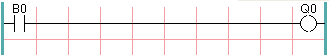
The input on the left, B0, a normally open contact, is connected to the coil (output) on the right, Q0. Now imagine a voltage gets applied to the leftmost end, because the input B0 turns true (e.g. the input is activated, or the user pushed the NO contact). The voltage has a direct path to reach the coil (output) on the right, Q0. As a consequence, the Q0 coil (output) will turn from 0/off/false to 1/on/true. If the user releases B0, the Q0 output quickly returns to 0/off/false.
4. Basic Latching On-Off Circuit
Building on the above example, suppose we add a switch that closes whenever the coil Q0 is active. This would be the case in a relay, where the coil can activate the switch contacts; or in a contactor, where there are often several small auxilliary contacts in addition to the large 3-phase contacts that are the primary feature of the contactor.
Since this auxilliary switch is driven from coil Q0 in our earlier example, we will give it the same number as the coil that drives it. This is the standard practice followed in all ladder programming, although it may seem strange at first to see a switch labeled the same as a coil. So let’s call this auxilliary contact Q0 and connect it across the B0 pushbutton contact from our earlier example.
Let’s take a look at it:
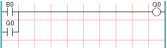
As before, when the user presses pushbutton B0, coil Q0 comes on. And when coil Q0 comes on, switch Q0 comes on. Now the interesting part happens. When the user releases pushbutton B0, coil Q0 does not stop as it did before. This is because switch Q0 of this circuit is effectively holding the user’s pushbutton pressed. So we see that switch Q0 is still holding coil Q0 on after the start pushbutton has been released.
This type of contact on a coil or relay, used in this way, is often called a holding contact, because it holds on the coil that it is associated with. It is also occasionally called a seal contact, and when it is active it is said that the circuit is sealed.
Unfortunately, our circuit so far has little practical use, because, although we have an on or start button in the form of pushbutton B0, we have no way to shut this circuit off once it is started. But that’s easy to fix. All we need is a way to interrupt the power to coil Q0. So let’s add a normally-closed (NC) pushbutton just ahead of coil Q0.
Here’s how that would look:
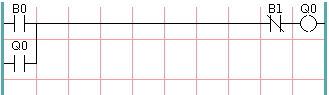
Now we have added off or stop pushbutton B1. If the user pushes it, contact from the rung to the coil is broken. When coil Q0 loses power, it drops to 0/off/false. When coil Q0 goes off, so does switch Q0, so the holding contact is broken, or the circuit is unsealed. When the user releases the stop pushbutton, contact is restored from the rung to coil Q0, but the rung has gone dead, so the coil doesn’t come back on.
This circuit has been used for decades on virtually every machine that has a three-phase motor controlled by a contactor, so it was inevitable that it would be adopted by ladder/PLC programmers. It is also a very safe circuit, in that if start and stop are both pressed at the same time, the stop function always wins.
This is the basic building block of much of ladder programming, so if you are new to it, you would do well to make sure that you understand how this circuit operates.