1. Ladder Concepts
Classic Ladder is a type of programming language originally implemented on industrial PLCs (it’s called Ladder Programming). It is based on the concept of relay contacts and coils, and can be used to construct logic checks and functions in a manner that is familiar to many systems integrators. Ladder consists of rungs that may have branches and resembles an electrical circuit. It is important to know how ladder programs are evaluated when running.
It seems natural that each line would be evaluated left to right, then the next line down, etc., but it doesn’t work this way in ladder logic. Ladder logic scans the ladder rungs 3 times to change the state of the outputs.
-
the inputs are read and updated
-
the logic is figured out
-
the outputs are set
This can be confusing at first if the output of one line is read by the input of a another rung. There will be one scan before the second input becomes true after the output is set.
Another gotcha with ladder programming is the "Last One Wins" rule. If you have the same output in different locations of your ladder the state of the last one will be what the output is set to.
2. Languages
The most common language used when working with Classic Ladder is ladder. Classic Ladder also supports Sequential Function Chart (Grafcet).
3. Components
There are 2 components to Classic Ladder.
-
The real time module classicladder_rt
-
The user space module (including a GUI) classicladder
3.1. Files
Typically classic ladder components are placed in the custom.hal file if your working from a Stepconf generated configuration. These must not be placed in the custom_postgui.hal file or the Ladder Editor menu will be grayed out.
|
Note
|
Ladder files (.clp) must not contain any blank spaces in the name. |
3.2. Realtime Module
Loading the Classic Ladder real time module (classicladder_rt) is possible from a HAL file, or directly using a halcmd instruction. The first line loads real time the Classic Ladder module. The second line adds the function classicladder.0.refresh to the servo thread. This line makes Classic Ladder update at the servo thread rate.
loadrt classicladder_rt
addf classicladder.0.refresh servo-thread
The speed of the thread that Classic Ladder is running in directly affects the responsiveness to inputs and outputs. If you can turn a switch on and off faster than Classic Ladder can notice it then you may need to speed up the thread. The fastest that Classic Ladder can update the rungs is one millisecond. You can put it in a faster thread but it will not update any faster. If you put it in a slower than one millisecond thread then Classic Ladder will update the rungs slower. The current scan time will be displayed on the section display, it is rounded to microseconds. If the scan time is longer than one millisecond you may want to shorten the ladder or put it in a slower thread.
3.3. Variables
It is possible to configure the number of each type of ladder object while loading the Classic Ladder real time module. If you do not configure the number of ladder objects Classic Ladder will use the default values.
Objects of most interest are numPhysInputs, numPhysOutputs, numS32in, and numS32out.
Changing these numbers will change the number of HAL bit pins available. numPhysInputs and numPhysOutputs control how many HAL bit (on/off) pins are available. numS32in and numS32out control how many HAL signed integers (+- integer range) pins are available.
For example (you don’t need all of these to change just a few):
loadrt classicladder_rt numRungs=12 numBits=100 numWords=10
numTimers=10 numMonostables=10 numCounters=10 numPhysInputs=10
numPhysOutputs=10 numArithmExpr=100 numSections=4 numSymbols=200
numS32in=5 numS32out=5
To load the default number of objects:
loadrt classicladder_rt
4. Loading the Classic Ladder user module
Classic Ladder HAL commands must executed before the GUI loads or the menu item Ladder Editor will not function. If you used the Stepper Config Wizard place any Classic Ladder HAL commands in the custom.hal file.
To load the user module:
loadusr classicladder
|
Note
|
Only one .clp file can be loaded. If you need to divide your ladder use Sections. |
To load a ladder file:
loadusr classicladder myladder.clp
Classic Ladder Loading Options
-
--nogui - (loads without the ladder editor) normally used after debugging is finished.
-
--modbus_port=port - (loads the modbus port number)
-
--modmaster - (initializes MODBUS master) should load the ladder program at the same time or the TCP is default port.
-
--modslave - (initializes MODBUS slave) only TCP
To use Classic Ladder with HAL without EMC:
loadusr -w classicladder
The -w tells HAL not to close down the HAL environment until Classic Ladder is finished.
If you first load ladder program with the --nogui option then load Classic Ladder again with no options the GUI will display the last loaded ladder program.
In AXIS you can load the GUI from File/Ladder Editor…
5. Classic Ladder GUI
If you load Classic Ladder with the GUI it will display two windows: section display, and section manager.
5.1. Sections Manager
When you first start up Classic Ladder you get an empty Sections Manager window.
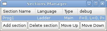
This window allows you to name, create or delete sections and choose what language that section uses. This is also how you name a subroutine for call coils.
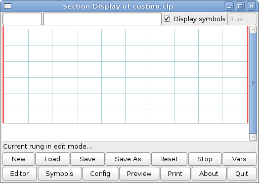
5.2. Section Display
When you first start up Classic Ladder you get an empty Section Display window. Displayed is one empty rung.

Most of the buttons are self explanatory:
The Vars button is for looking at variables, toggle it to display one, the other, both, then none of the windows.
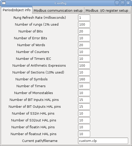
The Config button is used for modbus and shows the max number of ladder elements that was loaded with the real time module.
The Symbols button will display an editable list of symbols for the variables (hint you can name the inputs, outputs, coils etc).
The Quit button will shut down the user program meaning Modbus and the display. The real time ladder program will still run in the background.
The check box at the top right allows you to select whether variable names or symbol names are displayed
You might notice that there is a line under the ladder program display that reads "Project failed to load…" That is the status bar that gives you info about elements of the ladder program that you click on in the display window. This status line will now display HAL signal names for variables %I, %Q and the first %W (in an equation) You might see some funny labels, such as (103) in the rungs. This is displayed (on purpose) because of an old bug- when erasing elements older versions sometimes didn’t erase the object with the right code. You might have noticed that the long horizontal connection button sometimes didn’t work in the older versions. This was because it looked for the free code but found something else. The number in the brackets is the unrecognized code. The ladder program will still work properly, to fix it erase the codes with the editor and save the program.
5.3. The Variable Windows
This are two variable windows: the Bit Status Window (boolean) and the Watch Window (signed integer). The Vars button is in the Section Display Window, toggle the Vars button to display one, the other, both, then none of the variable windows.
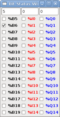
The Bit Status Window displays some of the boolean (on/off) variable data. Notice all variables start with the % sign. The %I variables represent HAL input bit pins. The %Q represents the relay coil and HAL output bit pins. The %B represents an internal relay coil or internal contact. The three edit areas at the top allow you to select what 15 variables will be displayed in each column. For instance, if the %B Variable column were 15 entries high, and you entered 5 at the top of the column, variables %B5 to %B19 would be displayed. The check boxes allow you to set and unset %B variables manually as long as the ladder program isn’t setting them as outputs. Any Bits that are set as outputs by the program when Classic Ladder is running can not be changed and will be displayed as checked if on and unchecked if off.
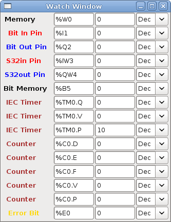
The Watch Window displays variable status. The edit box beside it is the number stored in the variable and the drop-down box beside that allow you to choose whether the number to be displayed in hex, decimal or binary. If there are symbol names defined in the symbols window for the word variables showing and the display symbols checkbox is checked in the section display window, symbol names will be displayed. To change the variable displayed, type the variable number, e.g. %W2 (if the display symbols check box is not checked) or type the symbol name (if the display symbols checkbox is checked) over an existing variable number/name and press the Enter Key.
5.4. Symbol Window
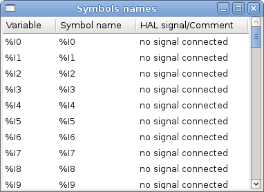
This is a list of symbol names to use instead of variable names to be displayed in the section window when the display symbols check box is checked. You add the variable name (remember the % symbol and capital letters), symbol name . If the variable can have a HAL signal connected to it (%I, %Q, and %W-if you have loaded s32 pin with the real time module) then the comment section will show the current HAL signal name or lack thereof. Symbol names should be kept short to display better. Keep in mind that you can display the longer HAL signal names of %I, %Q and %W variable by clicking on them in the section window. Between the two, one should be able to keep track of what the ladder program is connected to!
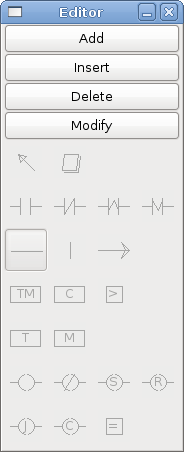
5.5. The Editor window
-
Add - adds a rung after the selected rung
-
Insert - inserts a rung before the selected rung
-
Delete - deletes the selected rung
-
Modify - opens the selected rung for editing
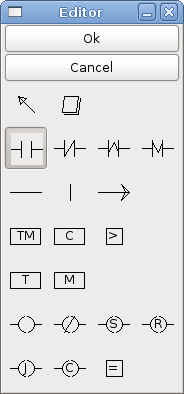
Starting from the top left image:
-
Object Selector, Eraser
-
N.O. Input, N.C. Input, Rising Edge Input , Falling Edge Input
-
Horizontal Connection, Vertical Connection , Long Horizontal Connection
-
Timer IEC Block, Counter Block, Compare Variable
-
Old Timer Block, Old Monostable Block (These have been replaced by the IEC Timer)
-
COILS - N.O. Output, N.C. Output, Set Output, Reset Output
-
Jump Coil, Call Coil, Variable Assignment
A short description of each of the buttons:
-
Selector - allows you to select existing objects and modify the information.
-
Eraser - erases an object.
-
N.O. Contact - creates a normally open contact. It can be an external HAL-pin (%I) input contact, an internal-bit coil (%B) contact or a external coil (%Q) contact. The HAL-pin input contact is closed when the HAL-pin is true. The coil contacts are closed when the corresponding coil is active (%Q2 contact closes when %Q2 coil is active).
-
N.C. Contact - creates a normally closed contact. It is the same as the N.O. contact except that the contact is open when the HAL-pin is true or the coil is active.
-
'Rising Edge Contact - creates a contact that is closed when the HAL-pin goes from False to true, or the coil from not-active to active.
-
Falling Edge Contact - creates a contact that is closed when the HAL-pin goes from true to false or the coil from active to not.
-
Horizontal Connection - creates a horizontal connection to objects.
-
Vertical Connection - creates a vertical connection to horizontal lines.
-
Horizontal Running Connection - creates a horizontal connection between two objects and is a quick way to connect objects that are more than one block apart.
-
IEC Timer - creates a timer and replaces the Timer.
-
Timer - creates a Timer Module (depreciated use IEC Timer instead).
-
Monostable - creates a one-shot monostable module
-
Counter - creates a counter module.
-
Compare - creates a compare block to compare variable to values or other variables. (eg %W1<=5 or %W1=%W2) Compare cannot be placed in the right most side of the section display.
-
Variable Assignment - creates an assignment block so you to assign values to variables. (eg %W2=7 or %W1=%W2) ASSIGNMENT functions can only be placed at the right most side of the section display.
6. Ladder objects
6.1. CONTACTS
Represent switches or relay contacts. They are controlled by the variable letter and number assigned to them.
The variable letter can be B, I, or Q and the number can be up to a three digit number eg. %I2, %Q3, or %B123. Variable I is controlled by a HAL input pin with a corresponding number. Variable B is for internal contacts, controlled by a B coil with a corresponding number. Variable Q is controlled by a Q coil with a corresponding number. (like a relay with multiple contacts). E.g. if HAL pin classicladder.0.in-00 is true then %I0 N.O. contact would be on (closed, true, whatever you like to call it). If %B7 coil is energized (on, true, etc) then %B7 N.O. contact would be on. If %Q1 coil is energized then %Q1 N.O. contact would be on (and HAL pin classicladder.0.out-01 would be true.)
-
N.O. Contact -
 (Normally Open)
When the variable is false the switch is off.
(Normally Open)
When the variable is false the switch is off.
-
N.C. Contact -
 (Normally
Closed) When the variable is false the switch is on.
(Normally
Closed) When the variable is false the switch is on.
-
Rising Edge Contact - When the variable changes from false to true, the switch is PULSED on.
-
Falling Edge Contact - When the variable changes from true to false, the switch is PULSED on.
6.2. IEC TIMERS
Represent new count down timers. IEC Timers replace Timers and Monostables.
IEC Timers have 2 contacts.
-
I - input contact
-
Q - output contact
There are three modes - TON, TOF, TP.
-
TON - When timer input is true countdown begins and continues as long as input remains true. After countdown is done and as long as timer input is still true the output will be true.
-
TOF - When timer input is true, sets output true. When the input is false the timer counts down then sets output false.
-
TP - When timer input is pulsed true or held true timer sets output true till timer counts down. (one-shot)
The time intervals can be set in multiples of 100ms, seconds, or minutes.
There are also Variables for IEC timers that can be read and/or written to in compare or operate blocks.
-
%TMxxx.Q - timer done (Boolean, read write)
-
%TMxxx.P - timer preset (read write)
-
%TMxxx.V - timer value (read write)
6.3. TIMERS
Represent count down timers. This is deprecated and replaced by IEC Timers.
Timers have 4 contacts.
-
E - enable (input) starts timer when true, resets when goes false
-
C - control (input) must be on for the timer to run (usually connect to E)
-
D - done (output) true when timer times out and as long as E remains true
-
R - running (output) true when timer is running
The timer base can be multiples of milliseconds, seconds, or minutes.
There are also Variables for timers that can be read and/or written to in compare or operate blocks.
-
%Txx.R - Timer xx running (Boolean, read only)
-
%Txx.D - Timer xx done (Boolean, read only)
-
%Txx.V - Timer xx current value (integer, read only)
-
%Txx.P - Timer xx preset (integer, read or write)
6.4. MONOSTABLES
Represent the original one-shot timers. This is now deprecated and replaced by IEC Timers.
Monostables have 2 contacts, I and R.
-
I - input (input) will start the mono timer running.
-
R - running (output) will be true while timer is running.
The I contact is rising edge sensitive meaning it starts the timer only when changing from false to true (or off to on). While the timer is running the I contact can change with no effect to the running timer. R will be true and stay true till the timer finishes counting to zero. The timer base can be multiples of milliseconds, seconds, or minutes.
There are also Variables for monostables that can be read and/or written to in compare or operate blocks.
-
%Mxx.R - Monostable xx running (Boolean, read only)
-
%Mxx.V - Monostable xx current value (integer, read only)
-
%Mxx.P - Monostable xx preset (integer, read or write)
6.5. COUNTERS
Represent up/down counters.
There are 7 contacts:
-
R - reset (input) will reset the count to 0.
-
P - preset (input) will set the count to the preset number assigned from the edit menu.
-
U - up count (input) will add one to the count.
-
D - down count (input) will subtract one from the count.
-
E - under flow (output) will be true when the count rolls over from 0 to 9999.
-
D - done (output) will be true when the count equals the preset.
-
F - overflow (output) will be true when the count rolls over from 9999 to 0.
The up and down count contacts are edge sensitive meaning they only count when the contact changes from false to true (or off to on if you prefer).
The range is 0 to 9999.
There are also Variables for counters that can be read and/or written to in compare or operate blocks.
-
%Cxx.D - Counter xx done (Boolean, read only)
-
%Cxx.E - Counter xx empty overflow (Boolean, read only)
-
%Cxx.F - Counter xx full overflow (Boolean, read only)
-
%Cxx.V - Counter xx current value (integer, read or write)
-
%Cxx.P - Counter xx preset (integer, read or write)
6.6. COMPARE
For arithmetic comparison. Is variable %XXX = to this number (or evaluated number)
The compare block will be true when comparison is true. you can use most math symbols:
-
+, - ,* , /, = (standard math symbols)
-
< (less than), > (greater than), <= (less or equal), >= (greater or equal), <> (not equal)
-
(, ) grouping
-
^ (exponent),% (modulus),& (and),| (or),. -
-
ABS (absolute), MOY (French for average) ,AVG (average)
For example ABS(%W2)=1, MOY(%W1,%W2)<3.
No spaces are allowed in the comparison equation. For example %C0.V>%C0.P is a valid comparison expression while %C0.V > %CO.P is not a valid expression.
There is a list of Variables down the page that can be used for reading from and writing to ladder objects. When a new compare block is opened be sure and delete the # symbol when you enter a compare.
To find out if word variable #1 is less than 2 times the current value of counter #0 the syntax would be:
%W1<2*%C0.V
To find out if S32in bit 2 is equal to 10 the syntax would be:
%IW2=10
Note: Compare uses the arithmetic equals not the double equals that programmers are used to.
6.7. VARIABLE ASSIGNMENT
For variable assignment, e.g. assign this number (or evaluated number) to this variable %xxx, there are two math functions MINI and MAXI that check a variable for maximum (0x80000000) and minimum values (0x07FFFFFFF) (think signed values) and keeps them from going beyond.
When a new variable assignment block is opened be sure to delete the # symbol when you enter an assignment.
To assign a value of 10 to the timer preset of IEC Timer 0 the syntax would be:
%TM0.P=10
To assign the value of 12 to s32out bit 3 the syntax would be:
%QW3=12
|
Note
|
When you assign a value to a variable with the variable assignment block the value is retained until you assign a new value using the variable assignment block. The last value assigned will be restored when LinuxCNC is started. |
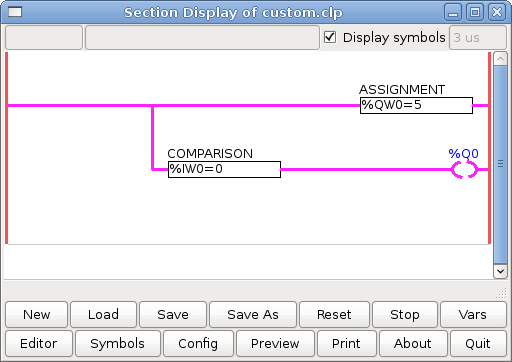
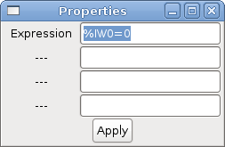
The following figure shows an Assignment and a Comparison Example. %QW0 is a S32out bit and %IW0 is a S32in bit. In this case the HAL pin classicladder.0.s32out-00 will be set to a value of 5 and when the HAL pin classicladder.0.s32in-00 is 0 the HAL pin classicladder.0.out-00 will be set to True.
6.8. COILS
Coils represent relay coils. They are controlled by the variable letter and number assigned to them.
The variable letter can be B or Q and the number can be up to a three digit number eg. %Q3, or %B123. Q coils control HAL out pins, e.g. if %Q15 is energized then HAL pin classicladder.0.out-15 will be true. B coils are internal coils used to control program flow.
-
N.O. COIL - (a relay coil.) When coil is energized it’s N.O. contact will be closed (on, true, etc)
-
N.C. COIL - (a relay coil that inverses its contacts.) When coil is energized it"s N.O. contact will be open (off, false, etc)
-
SET COIL - (a relay coil with latching contacts) When coil is energized it’s N.O. contact will be latched closed.
-
RESET COIL - (a relay coil with latching contacts) When coil is energized It’s N.0. contact will be latched open.
-
JUMP COIL - (a goto coil) when coil is energized ladder program jumps to a rung (in the CURRENT section) -jump points are designated by a rung label. (Add rung labels in the section display, top left label box)
-
CALL COIL - (a gosub coil) when coil is energized program jumps to a subroutine section designated by a subroutine number -subroutines are designated SR0 to SR9 (designate them in the section manager)
|
Warning
|
If you use a N.C. contact with a N.C. coil the logic will work (when the coil is energized the contact will be closed) but that is really hard to follow! |
6.8.1. JUMP COIL
A JUMP COIL is used to JUMP to another section, like a goto in BASIC programming language.
If you look at the top left of the sections display window you will see a small label box and a longer comment box beside it. Now go to Editor→Modify then go back to the little box, type in a name.
Go ahead and add a comment in the comment section. This label name is the name of this rung only and is used by the JUMP COIL to identify where to go.
When placing a JUMP COIL, add it in the rightmost position and change the label to the rung you want to JUMP to.
6.8.2. CALL COIL
A CALL COIL is used to go to a subroutine section then return, like a gosub in BASIC programming language.
If you go to the sections manager window hit the add section button. You can name this section, select what language it will use (ladder or sequential), and select what type (main or subroutine).
Select a subroutine number (SR0 for example). An empty section will be displayed and you can build your subroutine.
When you’ve done that, go back to the section manager and click on the your main section (default name prog1).
Now you can add a CALL COIL to your program. CALL COILs are to be placed at the rightmost position in the rung.
Remember to change the label to the subroutine number you chose before.
7. Classic Ladder Variables
These Variables are used in COMPARE or OPERATE to get information about, or change specs of, ladder objects such as changing a counter preset, or seeing if a timer is done running.
List of variables :
-
%Bxxx - Bit memory xxx (Boolean)
-
%Wxxx - Word memory xxx (32 bits signed integer)
-
%IWxxx - Word memory xxx (S32 in pin)
-
%QWxxx - Word memory xxx (S32 out pin)
-
%IFxx - Word memory xx (Float in pin) (converted to S32 in Classic Ladder)
-
%QFxx - Word memory xx (Float out pin) (converted to S32 in Classic Ladder)
-
%Txx.R - Timer xx running (Boolean, user read only)
-
%Txx.D - Timer xx done (Boolean, user read only)
-
%Txx.V - Timer xx current value (integer, user read only)
-
%Txx.P - Timer xx preset (integer)
-
%TMxxx.Q - Timer xxx done (Boolean, read write)
-
%TMxxx.P - Timer xxx preset (integer, read write)
-
%TMxxx.V - Timer xxx value (integer, read write)
-
%Mxx.R - Monostable xx running (Boolean)
-
%Mxx.V - Monostable xx current value (integer, user read only)
-
%Mxx.P - Monostable xx preset (integer)
-
%Cxx.D - Counter xx done (Boolean, user read only)
-
%Cxx.E - Counter xx empty overflow (Boolean, user read only)
-
%Cxx.F - Counter xx full overflow (Boolean, user read only)
-
%Cxx.V - Counter xx current value (integer)
-
%Cxx.P - Counter xx preset (integer)
-
%Ixxx - Physical input xxx (Boolean) (HAL input bit)
-
%Qxxx - Physical output xxx (Boolean) (HAL output bit)
-
%Xxxx - Activity of step xxx (sequential language)
-
%Xxxx.V - Time of activity in seconds of step xxx (sequential language)
-
%Exx - Errors (Boolean, read write(will be overwritten))
-
Indexed or vectored variables - These are variables indexed by another variable. Some might call this vectored variables. Example: %W0[%W4] => if %W4 equals 23 it corresponds to %W23
8. GRAFCET Programming
|
Warning
|
This is probably the least used and most poorly understood feature of Classic Ladder. Sequential programming is used to make sure a series of ladder events always happen in a prescribed order. Sequential programs do not work alone. There is always a ladder program as well that controls the variables. Here are the basic rules governing sequential programs: |
-
Rule 1 : Initial situation - The initial situation is characterized by the initial steps which are by definition in the active state at the beginning of the operation.There shall be at least one initial step.
-
Rule 2 : R2, Clearing of a transition - A transition is either enabled or disabled. It is said to be enabled when all immediately preceding steps linked to its corresponding transition symbol are active, otherwise it is disabled. A transition cannot be cleared unless it is enabled, and its associated transition condition is true.
-
Rule 3 : R3, Evolution of active steps - The clearing of a transition simultaneously leads to the active state of the immediately following step(s) and to the inactive state of the immediately preceding step(s).
-
Rule 4 : R4, Simultaneous clearing of transitions - All simultaneous cleared transitions are simultaneously cleared.
-
Rule 5 : R5, Simultaneous activation and deactivation of a step - If during operation, a step is simultaneously activated and deactivated, priority is given to the activation.
This is the SEQUENTIAL editor window Starting from the top left image: Selector arrow , Eraser Ordinary step , Initial (Starting) step Transition , Step and Transition Transition Link-Downside , Transition Link-Upside Pass-through Link-Downside , Pass-through Link-Upside Jump Link Comment Box [show sequential program]
-
ORDINARY STEP - has a unique number for each one
-
STARTING STEP - a sequential program must have one. This is where the program will start.
-
TRANSITION - This shows the variable that must be true for control to pass through to the next step.
-
STEP AND TRANSITION - Combined for convenience
-
TRANSITION LINK-DOWNSIDE - splits the logic flow to one of two possible lines based on which of the next steps is true first (Think OR logic)
-
TRANSITION LINK=UPSIDE - combines two (OR) logic lines back in to one
-
PASS-THROUGH LINK-DOWNSIDE - splits the logic flow to two lines that BOTH must be true to continue (Think AND logic)
-
PASS-THROUGH LINK-UPSIDE - combines two concurrent (AND logic) logic lines back together
-
JUMP LINK - connects steps that are not underneath each other such as connecting the last step to the first
-
COMMENT BOX - used to add comments
To use links, you must have steps already placed. Select the type of link, then select the two steps or transactions one at a time. It takes practice!
With sequential programming: The variable %Xxxx (eg. %X5) is used to see if a step is active. The variable %Xxxx.V (eg. %X5.V) is used to see how long the step has been active. The %X and %X.v variables are use in LADDER logic. The variables assigned to the transitions (eg. %B) control whether the logic will pass to the next step. After a step has become active the transition variable that caused it to become active has no control of it anymore. The last step has to JUMP LINK back only to the beginning step.
9. Modbus
Things to consider:
-
Modbus is a userspace program so it might have latency issues on a heavily laden computer.
-
Modbus is not really suited to Hard real time events such as position control of motors or to control E-stop.
-
The Classic Ladder GUI must be running for Modbus to be running.
-
Modbus is not fully finished so it does not do all modbus functions.
To get MODBUS to initialize you must specify that when loading the Classic Ladder userspace program.
loadusr -w classicladder --modmaster myprogram.clp
The -w makes HAL wait until you close Classic Ladder before closing realtime session. Classic Ladder also loads a TCP modbus slave if you add --modserver on command line.
-
1 - read coils
-
2 - read inputs
-
3 - read holding registers
-
4 - read input registers
-
5 - write single coils
-
6 - write single register
-
8 - echo test
-
15 - write multiple coils
-
16 - write multiple registers
If you do not specify a -- modmaster when loading the Classic Ladder user program this page will not be displayed.
-
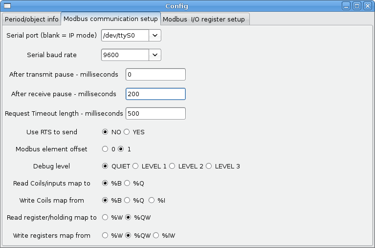
SERIAL PORT - For IP blank. For serial the location/name of serial driver eg. /dev/ttyS0 ( or /dev/ttyUSB0 for a USB-to-serial converter).
-
SERIAL SPEED - Should be set to speed the slave is set for - 300, 600, 1200, 2400, 4800, 9600, 19200, 38400, 57600, 115200 are supported.
-
PAUSE AFTER TRANSMIT - Pause (milliseconds) after transmit and before receiving answer, some devices need more time (e.g., USB-to-serial converters).
-
PAUSE INTER-FRAME - Pause (milliseconds) after receiving answer from slave. This sets the duty cycle of requests (it’s a pause for EACH request).
-
REQUEST TIMEOUT LENGTH - Length (milliseconds) of time before we decide that the slave didn’t answer.
-
MODBUS ELEMENT OFFSET - used to offset the element numbers by 1 (for manufacturers numbering differences).
-
DEBUG LEVEL - Set this to 0-3 (0 to stop printing debug info besides no-response errors).
-
READ COILS/INPUTS MAP TO - Select what variables that read coils/inputs will update. (B or Q).
-
WRITE COILS MAP TO - Select what variables that write coils will updated.from (B,Q,or I).
-
READ REGISTERS/HOLDING - Select what variables that read registers will update. (W or QW).
-
WRITE REGISTERS MAP TO - Select what variables that read registers will updated from. (W, QW, or IW).
-
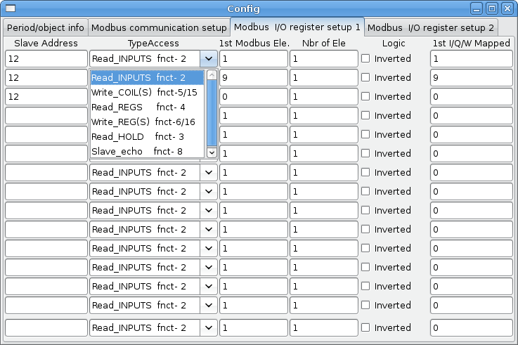
SLAVE ADDRESS - For serial the slaves ID number usually settable on the slave device (usually 1-256) For IP the slave IP address plus optionally the port number.
-
TYPE ACCESS - This selects the MODBUS function code to send to the slave (eg what type of request).
-
COILS / INPUTS - Inputs and Coils (bits) are read from/written to I, B, or Q variables (user selects).
-
REGISTERS (WORDS) - Registers (Words/Numbers) map to IW, W, or QW variables (user selects).
-
1st MODBUS ELEMENT - The address (or register number) of the first element in a group. (remember to set MODBUS ELEMENT OFFSET properly).
-
NUMBER OF ELEMENTS - The number of elements in this group.
-
LOGIC - You can invert the logic here.
-
1st%I%Q IQ WQ MAPPED - This is the starting number of %B, %I, %Q, %W, %IW, or %QW variables that are mapped onto/from the modbus element group (starting at the first modbus element number).
In the example above: Port number - for my computer /dev/ttyS0 was my serial port.
The serial speed is set to 9600 baud.
Slave address is set to 12 (on my VFD I can set this from 1-31, meaning I can talk to 31 VFDs maximum on one system).
The first line is set up for 8 input bits starting at the first register number (register 1). So register numbers 1-8 are mapped onto Classic Ladder’s %B variables starting at %B1 and ending at %B8.
The second line is set for 2 output bits starting at the ninth register number (register 9) so register numbers 9-10 are mapped onto Classic Ladder’s %Q variables starting at %Q9 ending at %Q10.
The third line is set to write 2 registers (16 bits each) starting at the 0th register number (register 0) so register numbers 0-1 are mapped onto Classic Ladder’s %W variables starting at %W0 ending at %W1.
It’s easy to make an off-by-one error as sometimes the modbus elements are referenced starting at one rather then 0 (actually by the standard that is the way it’s supposed to be!) You can use the modbus element offset radio button to help with this.
The documents for your modbus slave device will tell you how the registers are set up- there is no standard way.
The SERIAL PORT, PORT SPEED, PAUSE, and DEBUG level are editable for changes (when you close the config window values are applied, though Radio buttons apply immediately).
To use the echo function select the echo function and add the slave number you wish to test. You don’t need to specify any variables.
The number 257 will be sent to the slave number you specified and the slave should send it back. you will need to have Classic Ladder running in a terminal to see the message.
9.1. MODBUS Settings
Serial:
-
Classic Ladder uses RTU protocol (not ASCII).
-
8 data bits, No parity is used, and 1 stop bit is also known as 8-N-1.
-
Baud rate must be the same for slave and master. Classic Ladder can only have one baud rate so all the slaves must be set to the same rate.
-
Pause inter frame is the time to pause after receiving an answer.
-
MODBUS_TIME_AFTER_TRANSMIT is the length of pause after sending a request and before receiving an answer (this apparently helps with USB converters which are slow).
9.2. MODBUS Info
-
Classic Ladder can use distributed inputs/outputs on modules using the modbus protocol ("master": polling slaves).
-
The slaves and theirs I/O can be configured in the config window.
-
2 exclusive modes are available : ethernet using Modbus/TCP and serial using Modbus/RTU.
-
No parity is used.
-
If no port name for serial is set, TCP/IP mode will be used…
-
The slave address is the slave address (Modbus/RTU) or the IP address.
-
The IP address can be followed per the port number to use (xx.xx.xx.xx:pppp) else the port 9502 will be used per default.
-
2 products have been used for tests: a Modbus/TCP one (Adam-6051, http://www.advantech.com) and a serial Modbus/RTU one (http://www.ipac.ws).
-
See examples: adam-6051 and modbus_rtu_serial.
-
Web links: http://www.modbus.org and this interesting one: http://www.iatips.com/modbus.html
-
MODBUS TCP SERVER INCLUDED
-
Classic Ladder has a Modbus/TCP server integrated. Default port is 9502. (the previous standard 502 requires that the application must be launched with root privileges).
-
List of Modbus functions code supported are: 1, 2, 3, 4, 5, 6, 15 and 16.
-
Modbus bits and words correspondence table is actually not parametric and correspond directly to the %B and %W variables.
More information on modbus protocol is available on the internet.
9.3. Communication Errors
If there is a communication error, a warning window will pop up (if the GUI is running) and %E0 will be true. Modbus will continue to try to communicate. The %E0 could be used to make a decision based on the error. A timer could be used to stop the machine if timed out, etc.
9.4. MODBUS Bugs
-
In compare blocks the function %W=ABS(%W1-%W2) is accepted but does not compute properly. only %W0=ABS(%W1) is currently legal.
-
When loading a ladder program it will load Modbus info but will not tell Classic Ladder to initialize Modbus. You must initialize Modbus when you first load the GUI by adding --modmaster.
-
If the section manager is placed on top of the section display, across the scroll bar and exit is clicked the user program crashes.
-
When using --modmaster you must load the ladder program at the same time or else only TCP will work.
-
reading/writing multiple registers in Modbus has checksum errors.
10. Setting up Classic Ladder
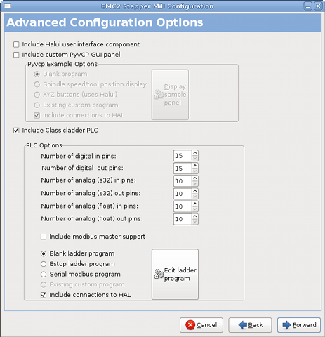
In this section we will cover the steps needed to add Classic Ladder to a Stepconf Wizard generated config. On the advanced Configuration Options page of Stepconf Wizard check off "Include Classic Ladder PLC".
10.1. Add the Modules
If you used the Stepconf Wizard to add Classic Ladder you can skip this step.
To manually add Classic Ladder you must first add the modules. This is done by adding a couple of lines to the custom.hal file.
This line loads the real time module:
loadrt classicladder_rt
This line adds the Classic Ladder function to the servo thread:
addf classicladder.0.refresh servo-thread
10.2. Adding Ladder Logic
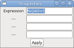
Now start up your config and select "File/Ladder Editor" to open up the Classic Ladder GUI. You should see a blank Section Display and Sections Manager window as shown above. In the Section Display window open the Editor. In the Editor window select Modify. Now a Properties window pops up and the Section Display shows a grid. The grid is one rung of ladder. The rung can contain branches. A simple rung has one input, a connector line and one output. A rung can have up to six horizontal branches. While it is possible to have more than one circuit in a run the results are not predictable.
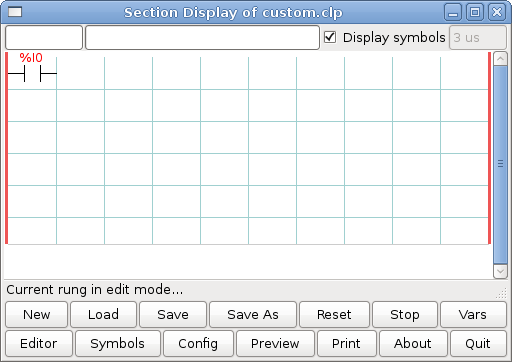
Now click on the N.O. Input in the Editor Window.
Now click in the upper left grid to place the N.O. Input into the ladder.
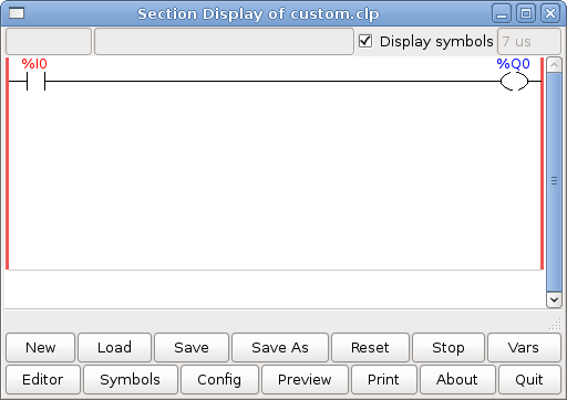
Repeat the above steps to add a N.O. Output to the upper right grid and use the Horizontal Connection to connect the two. It should look like the following. If not, use the Eraser to remove unwanted sections.

Now click on the OK button in the Editor window. Now your Section Display should look like this.
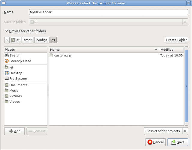
To save the new file select Save As and give it a name. The .clp extension will be added automatically. It should default to the running config directory as the place to save it.
Again if you used the Stepconf Wizard to add Classic Ladder you can skip this step.
To manually add a ladder you need to add add a line to your custom.hal file that will load your ladder file. Close your LinuxCNC session and add this line to your custom.hal file.
loadusr -w classicladder --nogui MyLadder.clp
Now if you start up your LinuxCNC config your ladder program will be running as well. If you select "File/Ladder Editor", the program you created will show up in the Section Display window.