1. Ladder Examples
1.1. Wrapping Counter
To have a counter that "wraps around" you have to use the preset pin and the reset pin. When you create the counter set the preset at the number you wish to reach before wrapping around to 0. The logic is if the counter value is over the preset then reset the counter and if the underflow is on then set the counter value to the preset value. As you can see in the example when the counter value is greater than the counter preset the counter reset is triggered and the value is now 0. The underflow output %Q2 will set the counter value at the preset when counting backwards.
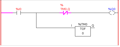
1.2. Reject Extra Pulses
This example shows you how to reject extra pulses from an input. Suppose the input pulse %I0 has an annoying habit of giving an extra pulse that spoils our logic. The TOF (Timer Off Delay) prevents the extra pulse from reaching our cleaned up output %Q0. How this works is when the timer gets an input the output of the timer is on for the duration of the time setting. Using a normally closed contact %TM0.Q the output of the timer blocks any further inputs from reaching our output until it times out.
1.3. External E-Stop
The External E-Stop example is in the /config/classicladder/cl-estop folder. It uses a pyVCP panel to simulate the external components.
To interface an external E-Stop to LinuxCNC and have the external E-Stop work together with the internal E-Stop requires a couple of connections through Classic Ladder.
First we have to open the E-Stop loop in the main HAL file by commenting out by adding the pound sign as shown or removing the following lines.
# net estop-out <= iocontrol.0.user-enable-out
# net estop-out => iocontrol.0.emc-enable-in
Next we add Classic Ladder to our custom.hal file by adding these two lines:
loadrt classicladder_rt
addf classicladder.0.refresh servo-thread
Next we run our config and build the ladder as shown here.
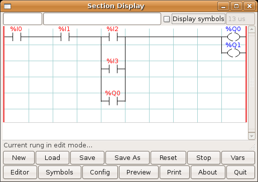
After building the ladder select Save As and save the ladder as estop.clp
Now add the following line to your custom.hal file.
# Load the ladder
loadusr classicladder --nogui estop.clp
I/O assignments
-
%I0 = Input from the pyVCP panel simulated E-Stop (the checkbox)
-
%I1 = Input from LinuxCNC’s E-Stop
-
%I2 = Input from LinuxCNC’s E-Stop Reset Pulse
-
%I3 = Input from the pyVCP panel reset button
-
%Q0 = Ouput to LinuxCNC to enable
-
%Q1 = Output to external driver board enable pin (use a N/C output if your board had a disable pin)
Next we add the following lines to the custom_postgui.hal file
# E-Stop example using pyVCP buttons to simulate external components
# The pyVCP checkbutton simulates a normally closed external E-Stop
net ext-estop classicladder.0.in-00 <= pyvcp.py-estop
# Request E-Stop Enable from LinuxCNC
net estop-all-ok iocontrol.0.emc-enable-in <= classicladder.0.out-00
# Request E-Stop Enable from pyVCP or external source
net ext-estop-reset classicladder.0.in-03 <= pyvcp.py-reset
# This line resets the E-Stop from LinuxCNC
 net emc-reset-estop iocontrol.0.user-request-enable =>
classicladder.0.in-02
# This line enables LinuxCNC to unlatch the E-Stop in Classic Ladder
net emc-estop iocontrol.0.user-enable-out => classicladder.0.in-01
# This line turns on the green indicator when out of E-Stop
net estop-all-ok => pyvcp.py-es-status
Next we add the following lines to the panel.xml file. Note you have to open it with the text editor not the default html viewer.
    <pyvcp>
    <vbox>
    <label><text>"E-Stop Demo"</text></label>
    <led>
    <halpin>"py-es-status"</halpin>
    <size>50</size>
    <on_color>"green"</on_color>
    <off_color>"red"</off_color>
    </led>
    <checkbutton>
    <halpin>"py-estop"</halpin>
    <text>"E-Stop"</text>
    </checkbutton>
    </vbox>
    <button>
    <halpin>"py-reset"</halpin>
    <text>"Reset"</text>
    </button>
    </pyvcp>
Now start up your config and it should look like this.
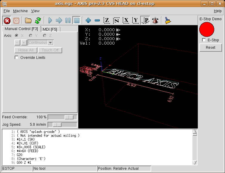
Note that in this example like in real life you must clear the remote E-Stop (simulated by the checkbox) before the AXIS E-Stop or the external Reset will put you in OFF mode. If the E-Stop in the AXIS screen was pressed, you must press it again to clear it. You cannot reset from the external after you do an E-Stop in AXIS.
1.4. Timer/Operate Example
In this example we are using the Operate block to assign a value to the timer preset based on if an input is on or off.
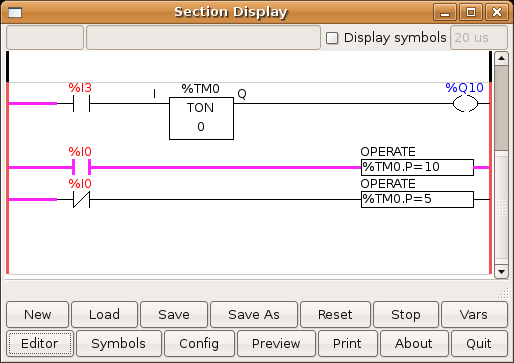
In this case %I0 is true so the timer preset value is 10. If %I0 was false the timer preset would be 5.
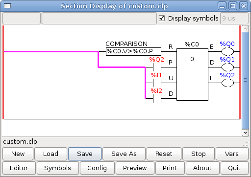
1.5. Tool Turret
-
This Example is not complete yet.
This is a program for one type of tool turret. The turret has a home switch at tool position 1 and another switch to tell you when the turret is in a lockable position. To keep track of the actual tool number one must count how many positions past home you are. We will use Classic Ladder’s counter block $CO.The counter is preset to 1 when RESET is true. The counter is increased by one on the rising edge of INDEX. We then COMPARE the counter value (%C0.V) to the tool number we want (in the example only checks for tool 1 and 2 are shown). We also OPERATE the counter value to a word variable (%W0) that (you can assume) is mapped on to a s32 out HAL pin so you can let some other HAL component know what the current tool number is. In the real world another s32 (in) pin would be used to get the requested tool number from LinuxCNC.You would have to load Classic Ladder’s real time module specifying that you want s32 in and out pins. See loading options above. [display turret sample]
1.6. Sequential Example
-
This Example is not complete yet.
This is a sequential program.
When the program is first started step one is active.
Then when %B0 is true, steps 2 and 3 are then active and step one is inactive.
Then when %B1 and/or %B2 are true, step 4 and/or 5 are active and step 2 and/or 3 are inactive.
Then when either %B3 OR %B4 are true, step 6 is true and steps 4 and 5 are inactive.
Then when %B5 is true step 1 is active and step 6 is inactive and it all starts again.
As shown, the sequence has been:
%B0 was true making step 2 and 3 active, then %B1 became true
(and still is-see the pink line through %B1)
making step 4 active and step 2 inactive.
Step 3 is active and waiting for %B2 to be true.
Step 4 is active and is waiting for %B3 to be true.
WOW, that was quite a mouthful!!