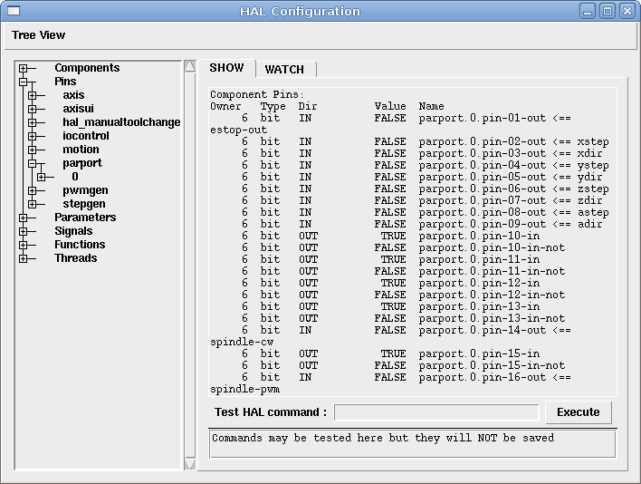
 Figure: HAL Configuration Window
More detailed information can be found in the man page for halcmd "man halcmd" in a terminal window. To see the HAL configuration and check the status of pins and parameters use the HAL Configuration window on the Machine menu in AXIS. To watch a pin status open the Watch tab and click on each pin you wish to watch and it will be added to the watch window.
The command "loadrt" loads a real time HAL component. Real time component functions need to be added to a thread to updated at the rate of the thread. You can not load a user space component into the real time space.
The syntax and an example:
loadrt <component> <options>
loadrt mux4 count=1
The command "addf" adds a function to a real time thread. You have to add a function from a HAL real time component to a thread to get the function to update at the rate of the thread.
If you used the Stepper Config Wizard to generate your config you will have two threads.
The syntax and an example:
addf <component> <thread>
addf mux4 servo-thread
The command "loadusr" loads a user space HAL component. User space programs are their own separate processes, which optionally talk to other HAL components via pins and parameters. You can not load real time components into user space.
Flags may be one or more of the following:
The syntax and examples:
loadusr <component> <options>
loadusr halui
loadusr -Wn spindle gs2_vfd -n spindle
in English is "loadusr wait for name spindle component gs2_vfd name spindle."
the -n spindle is part of the gs2_vfd component not the loadusr command.
The command "net" creates a "connection" between a signal and and one or more pins. If the signal does not exist net creates the new signal. This replaces the need to use the newsig command. The direction indicators "<= and =>" are only to make it easier for humans to follow the logic and are not used by the net command.
The syntax and an example:
net <signal-name> <pin-name> <opt-direction> <opt-pin-name>
net both-home-y <= paraport.0.pin-11-in
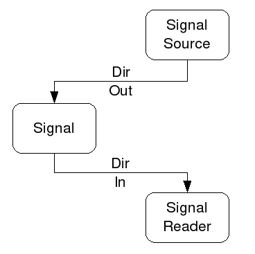
Each signal can only have one source (a HAL "out” pin) and as many readers (a HAL "in" pin) as you like. In the Dir column of the HAL Configuration window you can see which pins are "in" and which are "out". The following figure shows the "direction" of the signal from the source to the signal and then to the reader.
This example shows the signal xStep with the source being stepgen.0.out and with two readers parport.0.pin-02-out and parport.0.pin-08-out. Basically the value of stepgen.0.out is sent to the signal xStep and that value is then sent to parport.0.pin-02-out and parport.0.pin-08-out.
signal source destination destination
net xStep <= stepgen.0.out => parport.0.pin-02-out parport.0.pin-08-out
Since the signal xStep contains the value of stepgen.0.out (the source) you can use the same signal again to send the value to another reader. To do this just use the signal with the readers on another line.
net xStep stepgen.0.out => parport.0.pin-02-out
net xStep => parport.0.pin-08-out
The I/O pins like index-enable do not follow this rule.
The command "setp" sets the value of a pin or parameter. The valid values will depend on the type of the pin or parameter. It is an error if the data types do not match.
Some components have parameters that need to be set before use. Parameters can be set before use or while running as needed. You can not use setp on a pin that is connected to a signal.
The syntax and an example:
setp <pin/parameter-name> <value>
setp paraport.0.pin-08-out TRUE
The command "unlinkp" unlinks a pin from the connected signal. If no signal was connected to the pin prior running the command, nothing happens.
The syntax and an example:
unlinkp <pin-name>
unlinkp parport.0.pin-02-out
The command "linksp" creates a "connection" between a signal and one pin.
The syntax and an example:
linksp <signal-name> <pin-name>
linksp X-step parport.0.pin-02-out
The "linksp" command has been superseeded by the "net" command.
The command "linkps" creates a "connection" between one pin and one signal. It is the same as linksp but the arguments are reversed.
The syntax and an example:
linkps <pin-name> <signal-name>
linkps parport.0.pin-02-out X-Step
The "linkps" command has been superseeded by the "net" command.
the command "newsig" creates a new HAL signal by the name <signame> and the data type of <type>. Type must be "bit", "s32", "u32" or "float". Error if <signame> all ready exists.
The syntax and an example:
newsig <signame> <type>
newsig Xstep bit
More information can be found in the HAL manual or the man pages for halrun.
A bit value is an on or off.
A "float" is a floating point number. In other words the decimal point can move as needed.
For more information on floating point numbers see:
http://en.wikipedia.org/wiki/Floating_point
An "s32" number is a whole number that can have a negative or positive value.
A "u32" number is a whole number that is positive only.
If you used the Stepper Config Wizard to generate your config you will have up to three HAL files in your config directory.
Two parameters are automatically added to each HAL component when it is created. These parameters allow you to scope the execution time of a component.
.time
.tmax
Time is the number of CPU cycles it took to execute the function.
Tmax is the maximum number of CPU cycles it took to execute the function. Tmax is a read/write parameter so the user can set it to 0 to get rid of the first time initialization on the function's execution time.
Hal contains several real time logic components. Logic components follow a "Truth Table" that states what the output is for any given input. Typically these are bit manipulators and follow electrical logic gate truth tables.
If a component has a name option and you want to use that then you can not use the count. If you name them then you have to name all of them you want.
The "and2" component is a two input "and" gate. The truth table below shows the ouput based on each combination of input.
Syntax
and2 [count=N] or [names=name1[,name2...]]
Functions
and2.n
Pins
and2.N.in0 (bit, in)
and2.N.in1 (bit, in)
and2.N.out (bit, out)
Truth Table
| in0 | in1 | out |
| False | False | False |
| True | False | False |
| False | True | False |
| True | True | True |
The "not" component is a bit inverter.
Syntax
not [count=n] or [names=name1[,name2...]]
Functions
not.all
not.n
Pins
not.n.in (bit, in)
not.n.out (bit, out)
Truth Table
| in | out |
| True | False |
| False | True |
The "or2" component is a two input OR gate.
Syntax
or2[count=n] or [names=name1[,name2...]]
Functions
or2.n
Pins
or2.n.in0 (bit, in)
or2.n.in1 (bit, in)
or2.n.out (bit, out)
Truth Table
| in0 | in1 | out |
| True | False | True |
| True | True | True |
| False | True | True |
| False | False | False |
The "xor2" component is a two input XOR (exclusive OR)gate.
Syntax
xor2[count=n] or [names=name1[,name2...]]
Functions
xor2.n
Pins
xor2.n.in0 (bit, in)
xor2.n.in1 (bit, in)
xor2.n.out (bit, out)
Truth Table
| in0 | in1 | out |
| True | False | True |
| True | True | False |
| False | True | True |
| False | False | False |
An "and2" example connecting two inputs to one output.
loadrt and2 count=1
addf and2.0 servo-thread
net my-sigin1 and2.0.in0 <= paraport.0.pin-11-in
net my-sigin2 and2.0.in.1 <= paraport.0.pin-12-in
net both-on paraport.0.pin-14-out <= and2.0.out
In the above example one copy of and2 is loaded into real time space and added to the servo thread. Next pin 11 of the parallel port is connected to the in0 bit of the and gate. Next pin 12 is connected to the in1 bit of the and gate. Last we connect the and2 out bit to the parallel port pin 14. So following the truth table for and2 if pin 11 and pin 12 are on then the output pin 14 will be on.