Table of Contents
List of figures
List of tables
1 Pluto-P
1.1 General Info
The Pluto-P is an inexpensive ($60) FPGA board featuring the ACEX1K chip from Altera.
1.1.1 Requirements
- A Pluto-P board
- An EPP-compatible parallel port, configured for EPP mode in the system BIOS
1.1.2 Connectors
- The Pluto-P board is shipped with the left connector presoldered, with the key in the indicated position. The other connectors are unpopulated. There does not seem to be a standard 12-pin IDC connector, but some of the pins of a 16P connector can hang off the board next to QA3/QZ3.
- The bottom and right connectors are on the same .1" grid, but the left connector is not. If OUT2…OUT9 are not required, a single IDC connector can span the bottom connector and the bottom two rows of the right connector.
1.1.3 Physical Pins
- Read the ACEX1K datasheet for information about input and output voltage thresholds. The pins are all configured in "LVTTL/LVCMOS" mode and are generally compatible with 5V TTL logic.
- Before configuration and after properly exiting emc2, all Pluto-P pins are tristated with weak pull-ups (20kΩ min, 50kΩ max). If the watchdog timer is enabled (the default), these pins are also tristated after an interruption of communication between emc2 and the board. The watchdog timer takes approximately 6.5ms to activate. However, software bugs in the pluto_servo firmware or emc2 can leave the Pluto-P pins in an undefined state.
- In pwm+dir mode, by default dir is HIGH for negative values and LOW for positive values. To select HIGH for positive values and LOW for negative values, set the corresponding dout-NN-invert parameter TRUE to invert the signal.
- The index input is triggered on the rising edge. Initial testing has shown that the QZx inputs are particularly noise sensitive, due to being polled every 25ns. Digital filtering has been added to filter pulses shorter than 175ns (seven polling times). Additional external filtering on all input pins, such as a Schmitt buffer or inverter, RC filter, or differential receiver (if applicable) is recommended.
- The IN1…IN7 pins have 22-ohm series resistors to their associated FPGA pins. No other pins have any sort of protection for out-of-spec voltages or currents. It is up to the integrator to add appropriate isolation and protection. Traditional parallel port optoisolator boards do not work with pluto_servo due to the bidirectional nature of the EPP protocol.
1.1.4 LED
- When the device is unprogrammed, the LED glows faintly. When the device is programmed, the LED glows according to the duty cycle of PWM0 (LED = UP0 xor DOWN0) or STEPGEN0 (LED = STEP0 xor DIR0).
1.1.5 Power
- A small amount of current may be drawn from VCC. The available current depends on the unregulated DC input to the board. Alternately, regulated +3.3VDC may be supplied to the FPGA through these VCC pins. The required current is not yet known, but is probably around 50mA plus I/O current.
- The regulator on the Pluto-P board is a low-dropout type. Supplying 5V at the power jack will allow the regulator to work properly.
1.1.6 PC interface
- At present, only a single pluto_servo or pluto_step board is supported. At present there is no provision for multiple boards on one parallel port (because all boards reside at the same EPP address) but supporting one board per parallel port should be possible.
1.1.7 Rebuilding the FPGA firmware
The src/hal/drivers/pluto_servo_firmware/ and src/hal/drivers/pluto_step_firmware/ subdirectories contain the Verilog source code plus additional files used by Quartus for the FPGA firmwares. Altera's Quartus II software is required to rebuild the FPGA firmware. To rebuild the firmware from the .hdl and other source files, open the .qpf file and press CTRL-L. Then, recompile emc2.
Like the HAL hardware driver, the FPGA firmware is licensed under the terms of the GNU General Public License.
The gratis version of Quartus II runs only on Microsoft Windows, although there is apparently a paid version that runs on Linux.
1.1.8 For more information
The Pluto-P board may be ordered from http://www.knjn.com/ShopBoards_Parallel.html (US based, international shipping is available). Some additional information about it is available from http://www.fpga4fun.com/board_pluto-P.html and from the developer's blog.
1.2 pluto-servo: Hardware PWM and quadrature counting
The pluto_servo system is suitable for control of a 4-axis CNC mill with servo motors, a 3-axis mill with PWM spindle control, a lathe with spindle encoder, etc. The large number of inputs allows a full set of limit switches.
This driver features:
- 4 quadrature channels with 40MHz sample rate. The counters operate in "4x" mode. The maximum useful quadrature rate is 8191 counts per emc2 servo cycle, or about 8MHz for EMC2's default 1ms servo rate.
- 4 PWM channels, "up/down" or "pwm+dir" style. 4095 duty cycles from -100% to +100%, including 0%. The PWM period is approximately 19.5kHz (40MHz / 2047). A PDM-like mode is also available.
- 18 digital outputs: 10 dedicated, 8 shared with PWM functions. (Example: A lathe with unidirectional PWM spindle control may use 13 total digital outputs)
- 20 digital inputs: 8 dedicated, 12 shared with Quadrature functions. (Example: A lathe with index pulse only on the spindle may use 13 total digital inputs)
- EPP communication with the PC. The EPP communication typically takes around 100uS on machines tested so far, enabling servo rates above 1kHz.
1.2.1 Pinout
- UPx
- The "up" (up/down mode) or “pwm” (pwm+direction mode) signal from PWM generator X. May be used as a digital output if the corresponding PWM channel is unused, or the output on the channel is always negative. The corresponding digital output invert may be set to TRUE to make UPx active low rather than active high.
- DNx
- The "down" (up/down mode) or “direction” (pwm+direction mode) signal from PWM generator X. May be used as a digital output if the corresponding PWM channel is unused, or the output on the channel is never negative. The corresponding digital ouput invert may be set to TRUE to make DNx active low rather than active high.
- QAx, QBx
- The A and B signals for Quadrature counter X. May be used as a digital input if the corresponding quadrature channel is unused.
- QZx
- The Z (index) signal for quadrature counter X. May be used as a digital input if the index feature of the corresponding quadrature channel is unused.
- INx
- Dedicated digital input #x
- OUTx
- Dedicated digital output #x
- GND
- Ground
- VCC
- +3.3V regulated DC
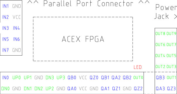 Figure: Pluto-Servo Pinout
|
Primary function |
Alternate Function |
Behavior if both functions used |
|
UP0 |
PWM0 |
When pwm-0-pwmdir is TRUE, this pin is the PWM output |
|
|
OUT10 |
XOR'd with UP0 or PWM0 |
|
UP1 |
PWM1 |
When pwm-1-pwmdir is TRUE, this pin is the PWM output |
|
|
OUT12 |
XOR'd with UP1 or PWM1 |
|
UP2 |
PWM2 |
When pwm-2-pwmdir is TRUE, this pin is the PWM output |
|
|
OUT14 |
XOR'd with UP2 or PWM2 |
|
UP3 |
PWM3 |
When pwm-3-pwmdir is TRUE, this pin is the PWM output |
|
|
OUT16 |
XOR'd with UP3 or PWM3 |
|
DN0 |
DIR0 |
When pwm-0-pwmdir is TRUE, this pin is the DIR output |
|
|
OUT11 |
XOR'd with DN0 or DIR0 |
|
DN1 |
DIR1 |
When pwm-1-pwmdir is TRUE, this pin is the DIR output |
|
|
OUT13 |
XOR'd with DN1 or DIR1 |
|
DN2 |
DIR2 |
When pwm-2-pwmdir is TRUE, this pin is the DIR output |
|
|
OUT15 |
XOR'd with DN2 or DIR2 |
|
DN3 |
DIR3 |
When pwm-3-pwmdir is TRUE, this pin is the DIR output |
|
|
OUT17 |
XOR'd with DN3 or DIR3 |
|
QZ0 |
IN8 |
Read same value |
|
QZ1 |
IN9 |
Read same value |
|
QZ2 |
IN10 |
Read same value |
|
QZ3 |
IN11 |
Read same value |
|
QA0 |
IN12 |
Read same value |
|
QA1 |
IN13 |
Read same value |
|
QA2 |
IN14 |
Read same value |
|
QA3 |
IN15 |
Read same value |
|
QB0 |
IN16 |
Read same value |
|
QB1 |
IN17 |
Read same value |
|
QB2 |
IN18 |
Read same value |
|
QB3 |
IN19 |
Read same value |
Table: Pluto-Servo Alternate Pin Functions
1.2.2 Input latching and output updating
- PWM duty cycles for each channel are updated at different times.
- Digital outputs OUT0 through OUT9 are all updated at the same time. Digital outputs OUT10 through OUT17 are updated at the same time as the pwm function they are shared with.
- Digital inputs IN0 through IN19 are all latched at the same time.
- Quadrature positions for each channel are latched at different times.
1.2.3 HAL Functions, Pins and Parameters
A list of all 'loadrt' arguments, HAL function names, pin names and parameter names is in the manual page, pluto_servo.9.
1.2.4 Compatible driver hardware
A schematic for a 2A, 2-axis PWM servo amplifier board is available (http://emergent.unpy.net/projects/01148303608). The L298 H-Bridge (L298 H-bridge) is inexpensive and can easily be used for motors up to 4A (one motor per L298) or up to 2A (two motors per L298) with the supply voltage up to 46V. However, the L298 does not have built-in current limiting, a problem for motors with high stall currents. For higher currents and voltages, some users have reported success with International Rectifier's integrated high-side/low-side drivers. (http://www.cnczone.com/forums/showthread.php?t=25929)
1.3 Pluto-step: 300kHz Hardware Step Generator
Pluto-step is suitable for control of a 3- or 4-axis CNC mill with stepper motors. The large number of inputs allows for a full set of limit switches.
The board features:
- 4 “step+direction” channels with 312.5kHz maximum step rate, programmable step length, space, and direction change times
- 14 dedicated digital outputs
- 16 dedicated digital inputs
- EPP communuication with the PC
1.3.1 Pinout
- STEPx
- The “step” (clock) output of stepgen channel x
- DIRx
- The “direction” output of stepgen channel x
- INx
- Dedicated digital input #x
- OUTx
- Dedicated digital output #x
- GND
- Ground
- VCC
- +3.3V regulated DC
While the “extended main connector” has a superset of signals usually found on a Step & Direction DB25 connector--4 step generators, 9 inputs, and 6 general-purpose outputs--the layout on this header is different than the layout of a standard 26-pin ribbon cable to DB25 connector.
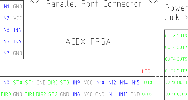 Figure: Pluto-Step Pinout
1.3.2 Input latching and output updating
- Step frequencies for each channel are updated at different times.
- Digital outputs are all updated at the same time.
- Digital inputs are all latched at the same time.
- Feedback positions for each channel are latched at different times.
1.3.3 Step Waveform Timings
The firmware and driver enforce step length, space, and direction change times. Timings are rounded up to the next multiple of 1.6μs, with a maximum of 49.6μs. The timings are the same as for the software stepgen component, except that “dirhold” and “dirsetup” have been merged into a single parameter “dirtime” which should be the maximum of the two, and that the same step timings are always applied to all channels.
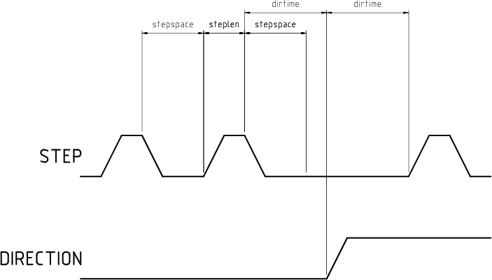 Figure: Pluto-Step Timings
1.3.4 HAL Functions, Pins and Parameters
A list of all 'loadrt' arguments, HAL function names, pin names and parameter names is in the manual page, pluto_step.9.
Index