Figure: Simple EMC2 Controlled Machine
For normal stepper based installations see the Getting Started Guide. Once EMC is installed and configured see the User Manual for information on using EMC.
The Integrator Manual scope is on more complex machines, configurations and installations. As the system integrator your task is bringing together all the component subsystems into a whole and ensuring that those subsystems function together. EMC being one of the subsystems.
The term CNC has taken on a lot of different meanings over the years. In the early days CNC replaced the hands of a skilled machinist with motors that followed commands in much the same way that the machinist turned the handwheels. From these early machines, a language of machine tool control has grown. This language is called RS274 and several standard variants of it have been put forward. It has also been expanded by machine tool and control builders in order to meet the needs of specific machines. If a machine changed tools during a program it needed to have tool change commands. If it changed pallets in order to load new castings, it had to have commands that allowed for these kinds of devices as well. Like any language, RS274 has evolved over time. Currently there are several dialects. In general each machine tool maker has been consistent within their product line but different dialects can have commands that cause quite different behavior from one machine to another.
More recently the language of CNC has been hidden behind or side-stepped by several programming schemes that are referred to as “Conversational1 programming languages.” One common feature of these kinds of programming schemes is the selection of a shape or geometry and the addition of values for the corners, limits, or features of that geometry.
The use of Computer Aided Design has also had an effect on the CNC programming languages. Because CAD drawings are saved as a list or database of geometries and variables associated with each, they are available to be interpreted into G-Code. These interpreters are called CAM (Computer Aided Manufacturing) programs.
Like the CAD converters, the rise of drawing programs, like Corel™ and the whole bunch of paint programs, converters have been written that will take a bitmap or raster or vector image and turn it into G-Code that can be run with a CNC.
You're asking yourself, “Why did I want to know this?” The answer is that the EMC2 as it currently exists does not directly take in CAD or any image and run a machine using it. The EMC2 uses a variant of the earlier CNC language named RS274NGC. (Next Generation Controller). All of the commands given to the EMC2 must be in a form that is recognized and have meaning to the RS274NGC interpreter. This means that if you want to carve parts that were drawn in some graphical or drafting program you will also have to find a converter that will transform the image or geometry list into commands that are acceptable to the EMC2 interpreter. Several commercial CAD/CAM programs are available to do this conversion. At least one converter (Ace) has been written that carries a copyright that makes it available to the public.
There has been recent talk about writing a “conversational” or geometric interface that would allow an operator to enter programs is much the same way that several modern proprietary controls enter programs but it isn't in there yet.
The EMC2 code can be compiled on almost any GNU-Linux Distribution (assuming it has been patched with a real time extension). In addition to the raw code, some binary distributions are available. The latest packages have been created around the Ubuntu GNU-Linux Distribution. Ubuntu is one of the distributions that is aimed at novice Linux users, and has been found to be very easy to use. Along with that, there are lots of places around the world that offer support for it. Installing EMC2 on it is trivial, see section [->]
The EMC2 will not run under a Microsoft (TM) operating system. The reason for this is that the EMC2 requires a real-time environment for the proper operation of its motion planning and stepper pulse outputs. Along with that, it also benefits from the much-needed stability and performance of the Linux OS.
The EMC code was started by the Intelligent Systems Division at the National Institute of Standards and Technology in the United States. The quotation below, taken from the NIST web presence some time back, should lend some understanding of the essential reasons for the existence of this software and of the NIST involvement in it.
As part of our (NIST) collaboration with the OMAC User's Group, we have written software which implements real-time control of equipment such as machine tools, robots, and coordinate measuring machines. The goal of this software development is twofold: first, to provide complete software implementations of all OMAC modules for the purpose of validating application programming interfaces; and second, to provide a vehicle for the transfer of control technology to small- and medium-sized manufacturers via the NIST Manufacturing Extension Partnership. The EMC software is based on the NIST Real-time Control System (RCS) Methodology, and is programmed using the NIST RCS Library. The RCS Library eases the porting of controller code to a variety of Unix and Microsoft platforms, providing a neutral application programming interface (API) to operating system resources such as shared memory, semaphores, and timers. The RCS Library also implements a communication model, the Neutral Manufacturing Language, which allows control processes to read and write C++ data structures throughout a single homogeneous environment or a heterogeneous networked environment. The EMC software is written in C and C++, and has been ported to the PC Linux, Windows NT, and Sun Solaris operating systems. When running actual equipment, a real-time version of Linux is used to achieve the deterministic computation rates required (200 microseconds is typical). The software can also be run entirely in simulation, down to simulations of the machine motors. This enables entire factories of EMC machines to be set up and run in a computer integrated manufacturing environment.
EMC has been installed on many machines, both with servo motors and stepper motors. Here is a sampling of the earliest applications.
After these early tests, Jon Elson found the Shaver Engineering notes and replaced a refrigerator sized Allen Bradley 7300 control on his Bridgeport with the EMC running on a Red Hat 5.2 distribution of Linux. He was so pleased with the result that he advertised the software on several newsgroups. He continues to use that installation and has produced several boards that are supported by the software.
From these early applications news of the software spread around the world. It is now used to control many different kinds of machines. More recently the Sherline company http://www.sherline.com has released their first CNC mill. It uses a standard release of the EMC.
The source code files that make up the controller are kept in a repository on http://git.linuxcnc.org. They are available for anyone to inspect or download. The EMC2 source code (with a few exceptions2) is released under the GNU General Public License (GPL). The GPL controls the terms under which EMC2 can be changed and distributed. This is done in order to protect the rights of people like you to use, study, adapt, improve, and redistribute it freely, now and in the future. To read about your rights as a user of EMC2, and the terms under which you are allowed to distribute any modifications you may make, see the full GPL at http://www.gnu.org/copyleft/gpl.html.
The Enhanced Machine Controller (EMC2) is a lot more than just another CNC mill program. It can control machine tools, robots, or other automated devices. It can control servo motors, stepper motors, relays, and other devices related to machine tools. In this handbook we focus on only a small part of that awesome capability, the minimill.
Figure [.] shows a simple block diagram showing what a typical 3-axis EMC2 system might look like. This diagram shows a stepper motor system. The PC, running Linux as its operating system, is actually controlling the stepper motor drives by sending signals through the printer port. These signals (pulses) make the stepper drives move the stepper motors. The EMC2 can also run servo motors via servo interface cards or by using an extended parallel port to connect with external control boards. As we examine each of the components that make up an EMC2 system we will remind the reader of this typical machine.
There are four main components to the EMC2 software: a motion controller (EMCMOT), a discrete I/O controller (EMCIO), a task executor which coordinates them (EMCTASK), and a collection of text-based or graphical user interfaces. An EMC2 capable of running a minimill must start some version of all four of these components in order to completely control it. Each component is briefly described below. In addition there is a layer called HAL (Hardware Abstraction Layer) which allows simple reconfiguration of EMC2 without the need of recompiling.
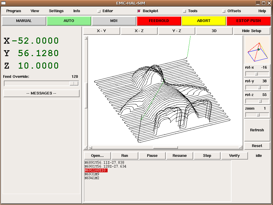
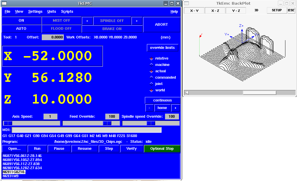
A graphical interface is the part of the EMC2 that the machine tool operator interacts with. The EMC2 comes with several types of user interfaces:
Tkemc and Mini will run on Linux, Mac, and Microsoft Windows if the Tcl/Tk programming language has been installed. The Mac and Microsoft Windows version can connect to a real-time EMC2 running on a Linux machine via a network connection, allowing the monitoring of the machine from a remote location. Instructions for installing and configuring the connection between a Mac or Microsoft Machine and a PC running the EMC2 can be found in the Integrators Handbook.
Motion control includes sampling the position of the axes to be controlled, computing the next point on the trajectory, interpolating between these trajectory points, and computing an output to the motors. For servo systems, the output is based on a PID compensation algorithm. For stepper systems, the calculations run open-loop, and pulses are sent to the steppers based on whether their accumulated position is more than a pulse away from their commanded position. The motion controller includes programmable software limits, and interfaces to hardware limit and home switches.
The motion controller is written to be fairly generic. Initialization files (with the same syntax as Microsoft Windows INI files) are used to configure parameters such as number and type of axes (e.g., linear or rotary), scale factors between feedback devices (e.g., encoder counts) and axis units (e.g., millimeters), servo gains, servo and trajectory planning cycle times, and other system parameters. Complex kinematics for robots can be coded in C according to a prescribed interface to replace the default 3-axis Cartesian machine kinematics routines.
Discrete I/O controllers are highly machine-specific, and are not customizable in general using the INI file technique used to configure the more generic motion controller. However, since EMC2 uses the HAL, reconfiguration of the I/O subsystem has become very powerful and flexible. EMC2 contains a Programmable Logic Controller module (behaves just like a hardware PLC) that can be used for very complex scenarios (tool changers, etc.).
In EMC2 there is only one big I/O controller, which provides support for all kinds of actions and hardware control. All its outputs and inputs are HAL pins (more on this later on), so you can use only the subset that fits your hardware and is necessary for your application.
The Task Executor is responsible for interpreting G and M code programs whose behavior does not vary appreciably between machines. G-code programming is designed to work like a machinist might work. The motion or turns of a handwheel are coded into blocks. If a machinist wanted his mill to move an inch in the +X direction at some feed rate, he might slowly turn the handwheel five turns clockwise in 20 seconds. The same machinist programming that same move for CNC might write the following block of code.
G1 F3 X1.000
G1 means that the machine is supposed to run at a programmed feed rate rather than at the fastest speed that it can (G0 is the way to command a rapid move like you would make above the work when not cutting). The F3 means that it should travel at 3 inches a minute or 3 millimeters a minute if it is working in metric mode. The X1.000 (assuming that the X axis started at zero) means the machine should move one inch in the positive X direction. You will read quite a bit more about G-code in the programming chapters .
Figure [.] is a block diagram of how a personal computer running the EMC2 is used to control a machine with G-code. The actual G-code can be sent using the MDI (Machine Device Interface) mode or it can be sent as a file when the machine is in Auto mode. These choices are made by the operator and entered using one of the Graphical User Interfaces available with the software.
G-code is sent to the interpreter which compares the new block with what has already been sent to it. The interpreter then figures out what needs to be done for the motion and input or output systems and sends blocks of canonical commands to the task and motion planning programs.
When an EMC2 is running, there are three different major modes used for inputting commands. These are Manual, Auto, and MDI. Changing from one mode to another makes a big difference in the way that the EMC2 behaves. There are specific things that can be done in one mode that can not be done in another. An operator can home an axis in manual mode but not in auto or MDI modes. An operator can cause the machine to execute a whole file full of G-codes in the auto mode but not in manual or MDI.
In manual mode, each command is entered separately. In human terms a manual command might be “turn on coolant” or “jog X at 25 inches per minute.” These are roughly equivalent to flipping a switch or turning the handwheel for an axis. These commands are normally handled on one of the graphical interfaces by pressing a button with the mouse or holding down a key on the keyboard. In auto mode, a similar button or key press might be used to load or start the running of a whole program of G-code that is stored in a file. In the MDI mode the operator might type in a block of code and tell the machine to execute it by pressing the <return> or <enter> key on the keyboard.
Some motion control commands are available and will cause the same changes in motion in all modes. These include abort, estop, and feed rate override. Commands like these should be self explanatory.
The AXIS user interface removes some of the distinctions between Auto and the other modes by making Auto-commands available at most times. It also blurs the distinction between Manual and MDI because some Manual commands like Touch Off are actually implemented by sending MDI commands.
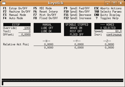
While an EMC2 is running, each of the modules keeps up a conversation with the others and with the graphical display. It is up to the display to select from that stream of information what the operator needs to see, and to arrange it on the screen in a way that makes it easy for the operator to understand. Perhaps the most important display is the mode the EMC2 is running in. You will want to keep your eye on the mode display.
Right up there with knowing what mode is active is consistent display of the position of each axis. Most of the interfaces will allow the operator to read position based upon actual or commanded position as well as machine or relative position.
These may all be exactly the same if no offsets have been applied and there is no deadband set in the INI file. Deadband is a small distance which is assumed to be close enough -- perhaps one stepper pulse or one encoder count.
It is also important to see any messages or error codes sent by the EMC2. These are used to request the operator change a tool, to describe problems in G-code programs, or to tell why the machine stopped running.
As you work your way through this text, you will be learning, bit by bit, how to set up and run a machine with your copy of the EMC2 software. While you are learning about setting up and running a minimill here, you will be thinking of other applications and other capabilities. These are the topics of the other linuxcnc.org handbooks.
The biggest task of a machine integrator is figuring out how to connect a PC running the EMC2 to a machine and configuring the software so that it runs the machine correctly.
Units can be confusing. You might ask, “Does it work in inches, feet, centimeters, millimeters, or what?” There are several possible answers to this question but the best one is that it works in the units that you set it to work in.
At a machine level, we set each axis's units to some value using an INI variable that looks like this.
UNITS = inch
or
UNITS = mm
After we have decided upon a value for the units for an axis, we tell the EMC2 how may step pulses or encoder pulses it should send or read for each unit of distance to be traveled. Once we have done this, the EMC2 knows how to count units of distance. However it is very important to understand that this counting of distance is different from the commanding of distance. You can command distance in millimeters or inches without even thinking about the units that you defined. There are G-codes that allow you to switch easily between metric and imperial.
1 One machine tool manufacturer, Hurco, claims to have a right to the use of these programming schemes and to the use of the term conversational when used in this context. back
2 some parts of EMC2 are released under the “Lesser” GPL (LPGL), which allows them to be used with proprietary software as long as certain restrictions are observed. back