
 Figure: ClassicLadder Var window
ClassicLadder is a free implementation of a ladder interpreter, released under the LGPL. It has been written by Marc Le Douarain.
He describes the beginning of the project on his website:
“I decided to program a ladder language only for test purposes at the start, in february 2001. It was planned, that I would have to participate to a new product after leaving the enterprise in which I was working at that time. And I was thinking that to have a ladder language in thoses products could be a nice option to considerate. And so I started to code the first lines for calculating a rung with minimal elements and displaying dynamically it under Gtk, to see if my first idea to realise all this works.
And as quickly I've found that it advanced quite well, I've continued with more complex elements : timer, multiples rungs, etc...
Voila, here is this work... and more : I've continued to add features since then.”
ClassicLadder has been adapted to work with emc2's HAL, and is currently beeing distributed along with emc2. If there are issues/problems/bugs please report them to the Enhanced Machine Controller project.
The most common language used when working with ClassicLadder is 'ladder'. ClassicLadder allows one to use other variants (like sequential function chart - Grafcet) too, however those aren't covered by the current documentation.
In the next chapters the main components of ClassicLadder will be described.
There are 2 components to ClassicLadder.
Typically classicladder components are placed in the custom.hal file if your working from a Stepconf generated configuration. These must not be placed in the custom_postgui.hal file or the Ladder Editor menu will be grayed out.
Ladder files (.clp) must not contain any blank spaces in the name.
Loading the ClassicLadder realtime module (classicladder_rt) is possible from a halfile, or directly using a halcmd instruction. The first line loads real time the ClassicLadder module. The second line adds the function classicladder.0.refresh to the servo thread. This makes ClassicLadder update at the servo thread rate.
loadrt classicladder_rt
addf classicladder.0.refresh servo-thread
The speed of the thread that ClassicLadder is running in directly effects the responsiveness to inputs and outputs. If you can turn a switch on and off faster than ClassicLadder can notice it then you may need to speed up the thread. The fastest that ClassicLadder can refresh the rungs is one millisecond. You can put it in a faster thread but it will not update any faster. If you put it in a slower then one microsecond thread then ClassicLadder will update the rungs slower. The current refresh rate will be displayed on the section display, it is rounded to microseconds.
It is possible to configure the number of each type of ladder object while loading the classicladder realtime module. If you do not configure the number of ladder objects ClassicLadder will use the default values.
| Object name: | variable name: | Default value: |
| Number of rungs | (numRungs) | 100 |
| Number of bits | (numBits) | 500 |
| Number of word variables | (numWords) | 100 |
| Number of timers | (numTimers) | 10 |
| Number of monostables | (numMonostables) | 10 |
| Number of counters | (numCounters) | 10 |
| Number of hal inputs bit pins | (numPhysInputs) | 50 |
| Number of hal output bit pins | (numPhysOuputs) | 50 |
| Number of arithmetic expressions | (numArithmExpr) | 50 |
| Number of sections | (numSections) | 10 |
| Number of symbols | (numSymbols) | 100 |
| Number of S32 inputs | (numS32in) | 0 |
| Number of S32 outputs | (numS32out) | 0 |
If you do not configure the number of ladder objects classicladder will use the default values. Objects of most interest are numPhysInputs and numPhysOutputs.
Changing these numbers will change the number of HAL bit pins available.
For example:
loadrt classicladder_rt numRungs=12 numBits=100 numWords=10 numTimers=10
numMonostables=10 numCounters=10 numPhysInputs=10 numPhysOutputs=10
numArithmExpr=100 numSections=4 numSymbols=200
To load the user module:
loadusr classicladder
To load a ladder file (filename must not have any spaces):
loadusr classicladder myladder.clp
To load the user module without the GUI:
loadusr classicladder --nogui
To load the user module with the modbus port number for modbus server over ethernet:
loadusr classicladder --modbus_port=port
To load the user module with a config file:
loadusr classicladder --config=file
Sets up the ClassicLadder for modbus master over serial or ethernet.
loadusr classicladder --config=my modbusfile --nogui myladder.clp
Use the GUI when setting up your system then change it to --nogui when running. The only other thing you can do while loading the user module is specify a ladder program to load. ladder programs are specified by the .clp ending.
If you load classicladder with the GUI it will display three windows: vars, section display, and section manager.
It displays some of the variable data and variable names. Notice all variable start with the % sign.
The three edit areas at the top allow you to select what 15 variable will be displayed in each column. For instance if there were 30 %I variable and you entered 10 at the top of the column, variable %I10 to %I25 would be displayed.
The check boxes allow you to set and un set variables but when classicladder is running hal will update the pins and change them.
Near the bottom are the %W variables. These are called word variable and represent positive and negative (signed) numbers and are used with compare and operate. By clicking on the variable, you can edit the number to display which ever you want.The edit box beside it is the number stored in the variable -you can change it- and the drop-down box beside that allow you to choose whether the number to be displayed is in hex, decimal or binary.
The %I variable represents HAL input bit pins. The %Q represents the relay coil and HAL output bit pins. The %B represents an internal relay coil or internal contact.
Figure: ClassicLadder Var windowMost of the buttons are self explanitory:
The config button is not used in EMC.
The symbols button will display an editable list of symbols for the variables (eg you can name the inputs, outputs, coils etc).
The symbols window will display the HAL signal names if present for %I, %Q and %W variables.
The quit button will only shut down the display-the ladder program will still run in the back ground.
The check box at the top right allows you to select whether variable names or symbol names are displayed
 Figure: ClassicLadder Section Display window
This window allows you to name, create or delete sections. This is also how you name a subroutine for call coils.
 Figure: ClassicLadder Section Manager window
Starting from the top left image:
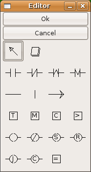 Figure: ClassicLadder Editor window
A short description of each of the buttons:
List of known variables :
JUMP COILs are used to 'JUMP' to another section-like a goto in BASIC programming language.
If you look at the top left of the sections display window you will see a small lable box and a longer comment box beside it. Now go to Editor->Modify then go back to the little box, type in a name.
Go ahead and add a comment in the comment section. This lable name is the name of this rung only and is used by the JUMP COIL to identify where to go.
When placing a JUMP COIL add it in the right most position and change the lable to the rung you want to JUMP to.
JUMP COILs should be placed as the last coil of a rung because of a bug. If there are coils after the JUMP COIL (in the same rung) they will be updated even if the JUMP COIL is true.1
CALL COILs are used to go to a subroutine section then return-like a gosub in BASIC programming language.
If you go to the sections manager window hit the add section button. You can name this section, select what language it will use (ladder or sequential), and select what type (main or subroutine).
Select a subroutine number (SR0 for exampe). An empty section will be displayed and you can build your subroutine.
When your done that, go back to the section manager and click on the your 'main' section (default name prog1).
Now you can add a CALL COIL to your program. CALL COILs are to be placed at the right most position in the rung.
Remember to change the lable to the subroutine number you choose before.
There can only be one CALL COIL per rung-the rest wil not be called.
As of EMC 2.2.0 The realtime module can export HAL s32 unsigned integer in/out pins.
You must specify how many s32 in/out pins you want when loading the realtime module (default is 0 of each).
For example to load 5 s32in and 5 s32out pins:
loadrt classicladder_rt numS32in=5 numS32out=5
This loads the realtime module with the default number of each ladder objects except for it also specifies 5 s32 in pins and 5 s32 out pins.
Values of this type can range from -2,147,483,648 to 2,147,483,647. They would correspond to some of the %W variables. For instance if you requested 5 s32in pins and 5 s32out pins %W0-%W4 would correspond to HAL pin name classicladder.0.s32in.00 -04 %W5-%W9 would be HAL pin name classicladder.0.s32out-00 -04 and %W10-99 would be regular (memory) variables.
If you request only s32out pins they would start at %W0 and regular words would start after them. so it maps %W variables like this. Number of s32in pins first (if any), then number of s32out pins second (if any) then regular memory variables.
For example if you add 2 s32in pins and 3 s32out pins the word relationship would be as shown in the following table.
| Word | Hal Pin |
| %W0 | classicladder.0.s32in.00 |
| %W1 | classicladder.0.s32in.01 |
| %W2 | classicladder.0.s32out.00 |
| %W3 | classicladder.0.s32out.01 |
| %W4 | classicladder.0.s32out.02 |
| %W5 | start of regular words |
1 If the JUMP COIL is true it should JUMP to the new rung right away and not update the rest of the coils of the current rung back