A depth map is a greyscale image where the brightness of each pixel corresponds to the depth (or height) of the object at each point.
Add the following lines to the [FILTER] section of your .ini file to make AXIS automatically invoke image-to-gcode when you open a .png, .gif, or .jpg image:
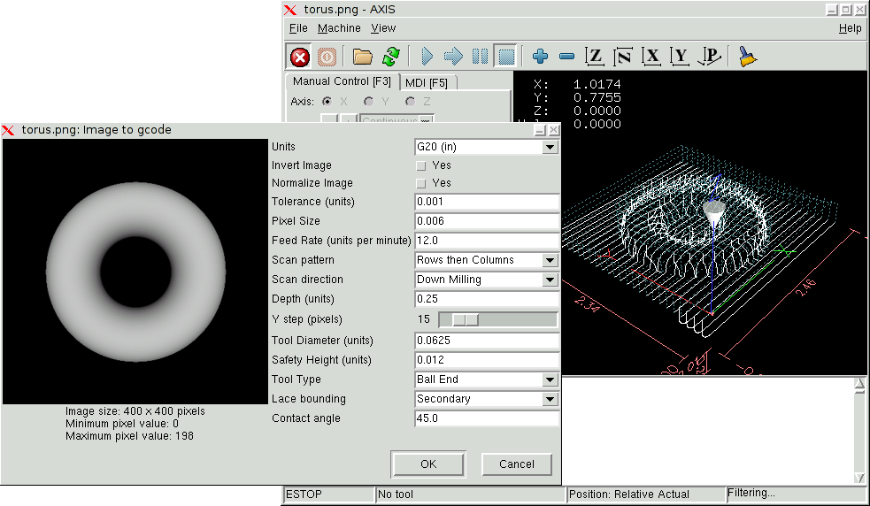
Start image-to-gcode either by opening an image file in AXIS, or by invoking image-to-gcode from the terminal, as follows:
Specifies whether to use G20 (inches) or G21 (mm) in the generated g-code and as the units for each option labeled (units).
If ``no'', the black pixel is the lowest point and the white pixel is the highest point. If ``yes'', the black pixel is the highest point and the white pixel is the lowest point.
If ``yes'', the darkest pixel is remapped to black, the lightest pixel is remapped to white.
When a series of points are within tolerance of being a straight line, they are output as a straight line. Increasing tolerance can lead to better contouring performance in emc, but can also remove or blur small details in the image.
One pixel in the input image will be this many units-usually this number is much smaller than 1.0. For instance, to mill a 2.5x2.5-inch object from a 400x400 image file, use a pixel size of .00625, because 2.5 / 400 = .00625.
The feed rate for the initial plunge movement
The feed rate for other parts of the path
Possible scan patterns are:
Possible scan directions are:
The top of material is always at Z=0. The deepest cut into the material is Z=-depth.
The distance between adjacent rows or columns. To find the number of pixels for a given units distance, compute distance/pixel size and round to the nearest whole number. For example, if pixel size=.006 and the desired step over distance=.015, then use a Step Over of 2 or 3 pixels, because .015/.006=2.5.
The diameter of the cutting part of the tool.
The height to move to for traverse movements. image-to-gcode always assumes the top of material is at Z=0.
The shape of the cutting part of the tool. Possible tool shapes are:
This controls whether areas that are relatively flat along a row or column are skipped. This option only makes sense when both rows and columns are being milled. Possible bounding options are:
When Lace bounding is not None, slopes greater than Contact angle are considered to be ``strong'' slopes, and slopes less than that angle are considered to be weak slopes.